
Universal Filament Snag Cutter
Print Profile(2)

Bill of Materials



Description
Boost Me (for free)
I put a lot of time and care into designing and testing this model, and your support is greatly appreciated!
Alternate Versions
|
|
|
What is this?
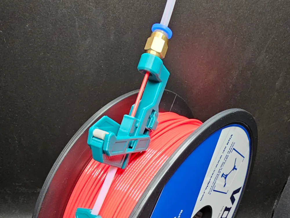
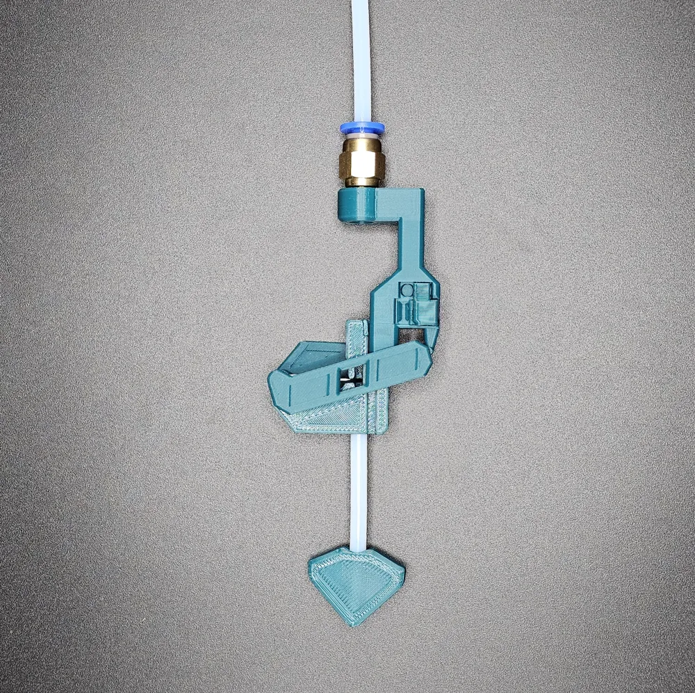
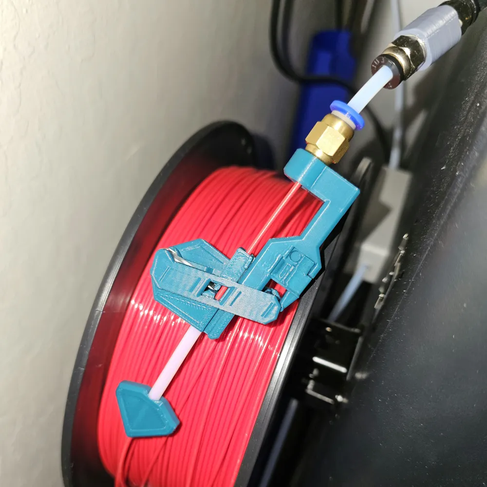
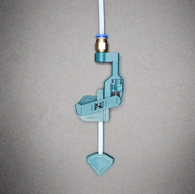
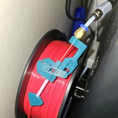
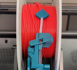
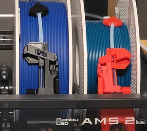
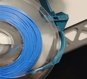


This is a device that attaches to the filament feed tube and automatically cuts filament when a snag is detected. This allows the printer or multi-material system to more gracefully handle the issue, whether it pauses the print at an opportune time or automatically switches to a different spool. This prevents tape or other obstructions from being pulled into the feed mechanisms, causing damage. The cutting feature can be turned on or off with a slider lock.
NOTE: Some of the photos and videos are from other similar cutter versions.

Compatibility
- AMS Style
- This is not compatible with the AMS. See the above models for AMS-compatible versions.
- Creality CFC
- This is compatible with the Creality CFS because it uses a standard PTFE tube as its inlet.
- Filament
- This relies on your feeder motor to generate enough force to cut through the filament. If your material is tough/strong/hard, then your feeder may not be able to generate enough force.
Materials Needed
Please note that it helps me if you purchase items by selecting them from the Bill of Materials between the Description and Comment Section below.
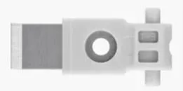
- Filament Cutter
- Spare blades may have been included in an X1 or a P1 series printer shipment, or you can purchase them by using the Bill of Materials located just above the comment section.
- PTFE Tube
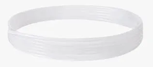
- At least 2.75 inches (70 mm) of 4 mm OD is required. Spare tubing may have been included in your AMS shipment, or you can purchase it by using the Bill of Materials located just above the comment section.
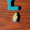
- Quick-Connect Fitting
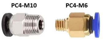
- There are two different Body models. One that is made with an M10 thread, and one made with an M6 thread. You can purchase the M6 version by using the Bill of Materials located just above the comment section.
- Filament
- The cutting trigger force is dependent on the Slide part filament's stiffness. I tested with ABS, but if you use a different material to print the part, then the trigger force may be too high or too low. Refer to the “Trigger Tuning” section below.
- Multi-Tool (Suggested)
- This is a helpful tool that helps hold and cut the Teflon tubing. https://makerworld.com/en/models/982416
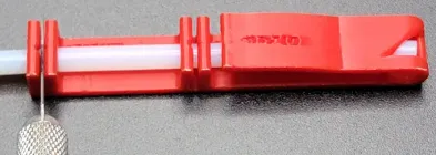
Mechanism Overview
- Actuate the Cutter mechanism by moving the Slide down into the Body. To adjust the trigger force, see the “Trigger Tuning” section below.
- Reset the Cutter mechanism by moving the Slide up out of the Body until it clicks and stops.
- Lock the Cutter by sliding the lock to the Right until an (X) is visible (note that the mechanism must be in the reset position to lock).
- Unlock the Cutter by sliding the lock to the Left until a circle is visible.
Printing
There are two different models to choose from, depending on the size of the thread on your quick-connect fitting. As described above, you may choose from an M10 or an M6 threaded fitting. I recommend purchasing the M6 thread fitting by using the Bill of Materials located just above the comment section.
Assembly Instructions
Note: The following video is for a different version, but it demonstrates the general functionality of the cutter.
1. Cut Teflon Tubing
- Depending on your setup, you may want your inlet tube longer or shorter. I have found that a length of 2.5 inches works well.
- Cut a Teflon (PTFE) Tube section to 1/4 inch (6 mm) and another section to 2.5 inches (64 mm).
- The AMS Tape Saver Multi-Tool is useful for cutting and handling the tubing.
2. Attach Teflon Tubes to Slide and Guide
- Insert the 1/4 inch tube into the hole at the bottom of the Slide.
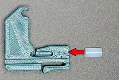
- Insert the 2-1/2 inch tube into the hole at the top of the slide and the other end into the Guide.
- Push the Tube into the Slide and the Guide until it stops.
- Hold the Slide and twist the Guide clockwise (righty tighty) while pushing them together to thread the tube into both parts.
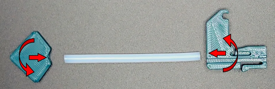
- If the tube begins to buckle/twist, you may want to use the AMS Tape Saver Multi-Tool as a clamp to grip and twist the Teflon tube.
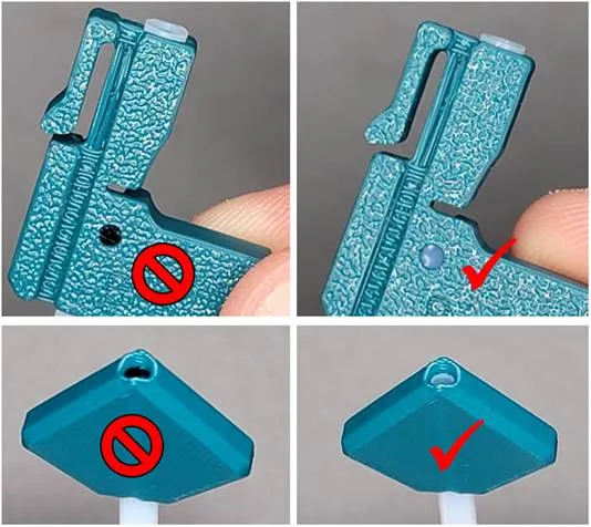
- Observe the Tube in the Slide inspection hole and the Guide end to ensure it is fully assembled.
3. Assemble the Arm into the Slide
Note: The default Slide design on Plate 1 seems to have the best trigger force. The trigger force can be changed by using a different Slide model. Refer to the “Trigger Tuning” section below.
- Remove the “REMOVE” tab from the Slide and flatten the nub/flashing.
- Orient the Arm as shown and slide the shaft into the slot.
- Rotate the Arm 90 degrees toward the Slide.
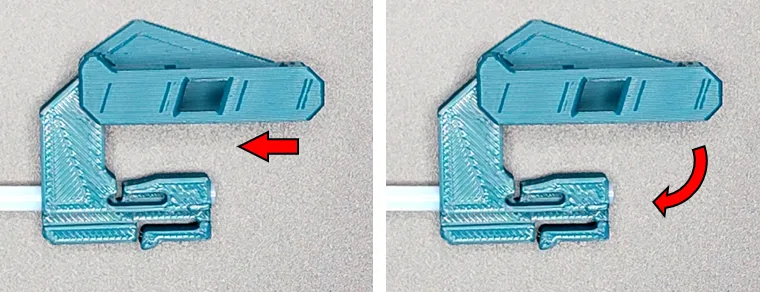
4. Attach the Cutter
Caution: The cutter is sharp! Handle with care.
- Insert the Cutter into the Slide slot and snap the pins into the Arm holes.
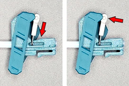
5. Attach the Body
- Line up the pins on the Body with the slots on the Arm.
- Insert the Slide into the Body while inserting the pins into the slots.
- The Slide will snap in place.
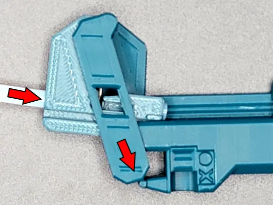
- Note that you can disassemble the mechanism by pushing a piece of filament into the hole on the side of the Body while pushing the Slide out of the Body.
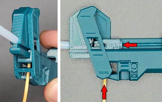
6. Attach the Lock
- Push the Lock into the Body until it snaps into place.
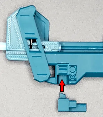
7. Attach the Quick Connect Fitting
- Hand-tighten the fitting into the bottom of the Body part. The threads are likely tapered, so they get tighter the farther they are screwed in. Be careful not to over-tighten such that the threads strip out or the base cracks.
Setup and Features
Note: The following video is for a different version, but it demonstrates the general functionality of the cutter.
1. Aligning Body and Guide
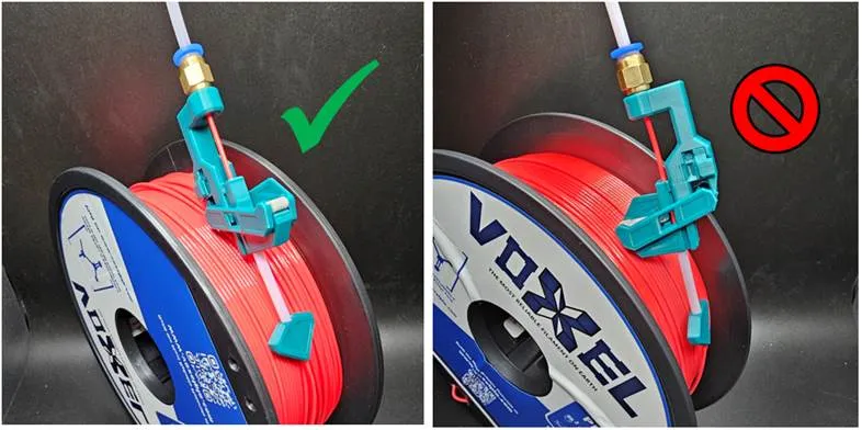
- It is recommended that the Body and the Guide are perpendicular to each other, and that the body (not the Arm or the Slide) rests against the spool as seen below. If the Arm or Slide is against the spool, then friction against the spool may trigger the cutter.
- If you lay the Cutter flat against the spool, then the Arm or Slide may get caught in slots in the sides of the spool.
- Everyone’s setup will be different, so use your best judgment and experiment to see what works.
2. Insert the Filament
- Ensure the lock is in the locked (X showing) position so you do not accidentally cut the filament while loading it! The (X) is visible when the Cutter is locked.
- Insert the end of the filament into the Guide.
- Push the filament through the Saver and into the printer.
3. Use during printing
- After the filament loading sequence has been completed, unlock the Cutter by sliding the lock to the Left until the circle is visible.
- Note: If you find that the cutter is triggering too soon or too late, refer to the Trigger Tuning section below.
4. Remove the filament
- Ensure the lock is in the locked (X showing) position.
- Rotate the roll of filament backward until the filament exits the Guide.
- Be sure not to let the end of the filament go free and get tangled.
- Remove the Spool.
Trigger Tuning
The material you use to print the model may be softer or harder than what I used for development. A softer material will create a weaker spring, resulting in a lighter trigger and less force to activate the cutter. The inverse is true for harder material. If you are having issues with the cutter triggering too soon (cutting without a tangle) or too late (the filament can't feed), don't worry. I have you covered.
The Slide part has the plastic spring incorporated into it, and there is a number on the back of the Slide indicating the thickness of the spring. The default Slide is marked with "1.8", indicating a spring thickness of 1.8 mm. A thicker spring will compensate for triggering too soon, and a thinner spring will compensate for triggering too late. Plates 2 through 9 have different Slide spring thicknesses, and they are labeled in Bambu Studio with the spring thickness on that plate (a minimum of 1.4 mm and a maximum of 3.0 mm).
If you have a cutter triggering too soon, look at the back of your Slide part and note the number. Print the plate with the Slide spring one increment thicker. Remove the current Slide and replace it with the thicker version. For example, if you have a "1.8" on the back of your Slide, then you should print the 2.0 mm plate. Test this new spring thickness and see if you are still encountering triggering that is too soon. If it is still triggering too soon, then keep increasing the spring width until you find a Slide spring that triggers at the appropriate time. Let me know if you are still having issues, and I will help.
Blade Gap Tuning
The blades from Bambu have a large variation in length. This can cause dragging/scraping of the blade against the filament, even if the blade is fully retracted. Multiple arm versions were created to compensate for this variation. Follow the procedure below:
- Print the standard Arm model on Plate 1. If no dragging occurs, then continue using this version.
- If the blade drags against the filament when retracted, then print the +0.2mm Arm on Plate 10. If no dragging occurs, then continue using this version.
- If the blade continues to drag against the filament when retracted, then print the +0.4mm Arm on Plate 11. If no dragging occurs, then continue using this version.
- If the blade continues to drag, then please message me, and I will see how I can help.
Boost Me (for free)
I put a lot of time and care into designing and testing this model, and your support is greatly appreciated!
Please check out the other models by Hexavalent!

License

You shall not share, sub-license, sell, rent, host, transfer, or distribute in any way the digital or 3D printed versions of this object, nor any other derivative work of this object in its digital or physical format (including - but not limited to - remixes of this object, and hosting on other digital platforms). The objects may not be used without permission in any way whatsoever in which you charge money, or collect fees.


Comment & Rating (118)