Tools and Accessories box for A1


Print Profile(1)

Bill of Materials


Description
Boost Me (for free)
I usually don’t ask for this, but I’ve noticed that many creators actively encourage it on other platforms—and it makes sense, as it helps increase visibility. So, if you can follow me, it would make difference. It’s a great way to support my work and show appreciation. For more insight subscribe my blog at: https://designrepcom.com/ This design is freely available for the community, but if you enjoy my work and would like to show your support, you can boost this project. Thanks!
Don't start to print this if you don't have the needed magnets… more info bellow
Don't start to print this if you don't have the needed magnets… more info bellow
Membership
Need a commercial license for this model? Learn more about the available options here.
A Refreshed Version of the Bambu Lab - Tools and Accessories Box
After the tremendous success of the original Bambu Lab - Tools and Accessories Box, which garnered thousands of downloads and makes, I decided it was time to refresh and enhance this project. This updated version introduces significant improvements across almost every aspect while maintaining the core functionality that made the original so popular.

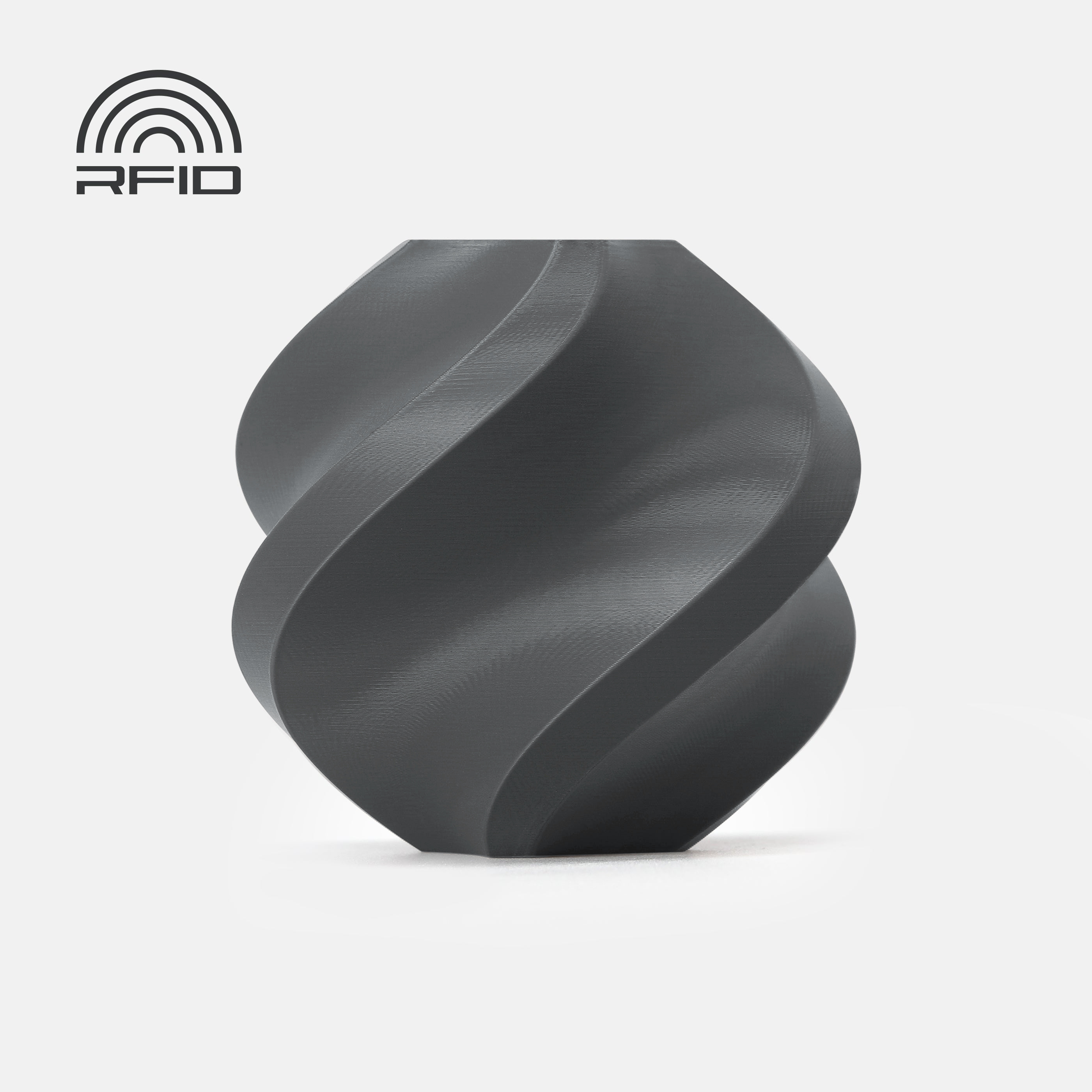
And here is the new version for comparation and without any accessories or tools.

Storage Capacity
This version of the case allows you to store:
First Half of the Case
- 4 Nozzles
- 1 Pliers (I used this one, it seems commonly available)
- 4 Filament Cutters (Let me know if, like me, you find this works faster with CF filament.)
4 Silicone Socks
Second Half of the Case
- 1 Kit of Hexagonal Keys, along with a nozzle unclogging needle in the same compartment.
- 1 Kit: Small Scraper + Spare Blade
- 2 Filament Wipers
- 2 PTFE tube remover
2 Lubrification tubs

Additional Storage
Both halves of the case feature pockets with lids for storing other accessories, such as lubricants, small bags with screws, and more.
And one compartment with trapdoor, inside divider wall for mix parts
Key Improvements
New Design, more actual
The new version features a more modern aesthetic, though I understand design preferences can vary. The updated look aims to balance form and function while staying true to the original concept.
 |  |
Enhanced Dimensional and Geometric Precision
The modules now benefit from the advanced dimensional and geometric precision I developed in my most recent project:
UMSS - Universal Modular Storage System
 |  |  |
This project builds on its predecessor:

Magnetic Closure System
The closing mechanism has been upgraded to a magnetic system, inspired by my previous projects. This makes the case more user-friendly and provides a reliable, sleek solution compared to the earlier version.
Monobloc Structure
Unlike the original Tools and Accessories Box, this new case features an almost monobloc structure. This design choice addresses structural issues from the earlier version, improving durability and simplifying assembly.
Design Challenges: The Handle
One of the most complex aspects of this update was the handle. My goal was to integrate it seamlessly into the body of the case.
For this version, I redesigned the handle, choosing to keep it attached to the main body rather than making it a detachable piece, as I did in the MMSS case (link here). While a detachable handle might have simplified some aspects, it would have disrupted the clean, cohesive design I envisioned.
 |  |
The Trade-Off
The main challenge with the handle was the support material required during printing. Adjusting the model’s orientation to reduce support material was partially feasible but would have compromised the areas for the magnets. This trade-off was a deliberate decision to balance design, functionality, and printability.

If I had printed it at a 45º angle, there wouldn’t be any marks, but the resolution of the logo would be compromised. Additionally, the darker surface you see inside, which separates the different zones, would need to be printed separately and later assembled. Printing everything together would require a material change on nearly every layer— and there are many. As I’m against material waste, I decided not to include this option.
 |  |
However, if you think the solution of printing at a 45º angle with the separating surface as a standalone part is worth exploring, I can create that configuration. The grooves for the magnets remain on the main body. However, the pockets for the magnets that keep the case closed should be integrated into the separating surface.
Flexibility Through Modularity
For users seeking more flexibility—whether they find the number of hotend pockets excessive or insufficient—the UMSS and MMSS projects offer an ideal solution. Both systems are fully modular, allowing for personalized configurations to suit a variety of needs.
Other Parts
Some of the parts you see here, such as the keys and the scraper, are available as separate models:
- Handles for Bambu Lab X1 and P1 Hexagonal Keys – View model here
- Small Scraper – View model here
Regarding the tool I use to make this
I’d like to clarify a common question I receive about the tools I use for my projects. This project was modeled using Autodesk’s Fusion CAD software, which I find ideal for creating complex 3D models.
The negatives for the parts were also created there, but they were made using a technique that I’ll explain in a few days for those interested, either through a video or a short article. But only after releasing the version for the A1. ;)
Over the years, I have used other CAD applications, but I ultimately chose Fusion 360 due to its flexibility and ease of use. It is also one of the most accessible CAD tools for this type of community, offering free licenses for personal use. Additionally, its mesh modeling tools are some of the bests I’ve worked with.Other tools are also used to achieve the final result. For example, rendered images are sometimes generated directly in Fusion 360, while others are done using Blender (I dont model in this software, it is not parametric neither it has a timeline.
It's rare for me to start a project directly in CAD, as it can disrupt my creative flow. For this reason, I prefer to begin with hand sketches, sometimes with great detail, and only afterward do I translate the design into the CAD tool.I hope this answers one of the frequent questions I receive.
Print and assembly instructions
Against my will, I am placing this information on the main page (this one), as the proper location for this information is in the specific section here on Makerworld dedicated solely to printing instructions. However, a member became very upset with me and gave the project the lowest rating because he didn't know the printer would pause for the placement of the magnets. Going even further, he insinuated that I was trying to deceive them when I emphasized that the information had been there from the very beginning. To avoid further confusion and complications, I am now adding this information to this page.
Printing Recommendations
Regarding the printing process, the 3MF profile I created has undergone several tests. Different printing orientations were experimented with to reduce both the quantity and the difficulty of support removal. The figure illustrates one of these options.
 |  |
That said, feel free to experiment. If you find a better solution that offers improved print quality, please share it with me ;)
I tested printing with support material identical to the piece (in this case, basic PLA), with dedicated support material for PLA, and with PVA (water-soluble). Without a doubt, the latter option proved to be the best. If you haven’t tried PVA yet and have the opportunity to purchase it, I strongly recommend doing so.
PVA can last a long time if you use it solely for the interface layer between the support and the part. Once printed, simply submerge the piece in warm water (below 50°C) and wait a few minutes for the PVA to fully dissolve.
Thus, in my experiments, which were more numerous than I care to admit, I concluded that the configuration offering the best results in terms of material availability and cost is using PETG for the interface layer when the case is printed in PLA, or vice versa.
The results were so good that I decided to offer this configuration as the default.
That said, there are many PLA and PETG variations, and the differences between them can be significant. Test with a small part or use the "cut" tool to section the piece and print a portion of the handle. Observe the results—if they turn out well, you can try printing the entire piece.
- Special profile, with an interface layer set to a PETG material slot on the AMS. Remember, if you are planning to print this case in PETG, and I can say that it looks nice too, then change the material on the “Support/raft interface” to PLA

For this to work, purging the material do clean any remains of the old material is necessary, especially with changing from the interface material back to the part material. The part can break when removing it from the plate because of this. I too added some extra configurations on the 3mf for this not to happen.
Important Notes
However, there is one thing you absolutely should not do:
Do not use matte PLA for any of the situations mentioned above. This material has a strong tendency to adhere to itself, making the removal of supports extremely difficult—if not impossible in most cases.
In this project, it’s critical to calibrate your filament properly, as the dimensional adjustments have very tight tolerances. Without calibration, some parts may not fit as intended.
If you’re unsure, use the cutting tool in Bambu Studio to print a small section of a specific area (e.g., a nozzle). Test if the nozzle fits snugly but without excessive force.
Please note that components like hex keys, nozzles, and others are subject to mechanical stress and may warp over time. Therefore, it’s best to test the fit with new components for accurate results
About the Lids
Regarding the lids found inside, there are two profiles available:
- 0.2mm Nozzle Profile (Lids 0.2 Nozzle.3mf)
- This option provides the best results in terms of precision and finish.
- 0.4mm Regular Nozzle Profile (Lids 0.4 Nozzle.3mf)
- Suitable for standard nozzles, offering good performance while maintaining convenience.
The magnets on the lids and pockets should be glued. It is possible to cover the one on the case, like the rest of the magnets, but not on the Lid because the way it's printed (vertical)
Material List
(Reference numbers from Bambu Lab are included for convenience, but, of course, feel free to purchase from any supplier that suits your needs.)
- 2x M3 Carbon Steel Hex Nut – (Bambu Lab reference: AB005)
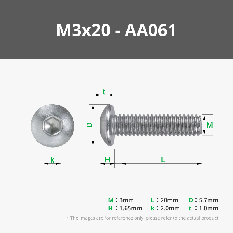
2x M3x20 BHCS Machine Screw – (Bambu Lab reference: AA061)

Bottom Lid

Regarding the 8x4 magnets, that are needed, makers supply doesn't have them at this momento, you can buy them elsewhere on use two staked magnets of 8x2mm (it is the same). If you find them on Maker's supply, please let me know to update this description.
And for the hinges:
- 2x M3 Carbon Steel Hex Nut – (Bambu Lab reference: AB005)
- 2x M3x20 BHCS Machine Screw – (Bambu Lab reference: AA061)
Filament Used
These are the combinations I prefer the most:
- Basic PLA - Light Gray
- Basic PLA - Dark Gray
Magnet Insertion Instructions
The print will pause at specific points to allow for magnet insertion. Ensure that the magnets are inserted with the correct orientation on the lids (both the small internal lids and the main lids of the case). The magnets should be oriented so that they attract each other.
Regarding the pause sequence, which can be very easily seen on bambu studio when the model is sliced. That bar on the right will show some pauses, move the slider up and down to see where the pause is located; the next layer after the pause should close the pocket for that magnet. See images obove.
Regarding the magnets and the nozzles
Bambu Lab does sometimes ship nozzles with reversed polarity, so it’s essential to test the orientation before fixing the magnets permanently. What worked for me was to test each magnet with its corresponding nozzle, and then, with all the magnets attached to the nozzles, I kept them together near the printer until it was time to insert them. This way, I could guarantee the correct alignment. I also noticed that, in my case, the nozzle with reversed polarity magnet was the ones with non-hardened metal, but this might just be a coincidence. At some point, I've consider not using magnets for the nozzles and instead use something ferromagnetic, like a steel nut, to attract the nozzle, since it already has its own magnet, but that didn't go forward.
I understand that for some people, placing the magnets can be a bit tricky, but if you take your time, it should work out well.
Insert the nuts on the hinge
For those not used to assembling mechanical and 3D-printed parts, there are a few tricks you might not know...
If you have a longer screw, it's easier:
- Align the covers.
- Insert the screw first.
- Then, place the nut at the tip of the screw and start threading it, ensuring the nut aligns with the hexagonal socket. Done
If you don’t have a screw with a longer shaft, you can do the following:
- Thread the screw 2 or 3 turns into the nut (without using the covers).
- Use the screw to guide the nut into its hole. —if it fits easily, great. Do the same for the other side. The nuts should be guided into position but not fall out. If there's a small burr preventing the nut from entering, you can use a file or, if you don’t have one, a utility knife to remove the burr.
- Position the covers and then carefully insert the screw into its corresponding hole. Go slowly to avoid dislodging the nut.
Change Log:
19/12/2024 - First Release
Curious About My Tools? Check This Out!
For those of you who often ask about the tools I use to bring ideas to life, this article, The Journey From Idea To Object (Part I), offers some insights into the initial stages. It highlights the use of various tools, including software like Autodesk Fusion for CAD design, Blender for render and Bambu Studio for 3D printing preparation, and other... So, if you're curious about the software and hardware too, that I've incorporate in my workflow, take a look at the link for more details!" – Visit https://designrepcom.com/ for much more.
License
You shall not share, sub-license, sell, rent, host, transfer, or distribute in any way the digital or 3D printed versions of this object, nor any other derivative work of this object in its digital or physical format (including - but not limited to - remixes of this object, and hosting on other digital platforms). The objects may not be used without permission in any way whatsoever in which you charge money, or collect fees.
Comment & Rating (215)