FRESH – Friction Reducing Spool Holder for Mini A1
FRESH – Friction Reducing Spool Holder for Mini A1


Print Profile(1)

Description
If you print TPU with the A1 Mini, the softer the TPU you use, the higher the chance that friction will stretch your filament on its way into the extruder, and that will result in under-extrusion. This will happen even if all other printing parameters are optimized. That stretch is caused by friction, and is an obstacle good TPU prints.
The FRESH spindle replacement eliminates most of the friction between filament rolls and the A1 Mini spool holder while preserving the position, size and location of the spool holder. FRESH particularly benefits softer TPU’s (Shore 80A to 90A), but also alleviates friction on cardboard spools (regardless of filament type). Here is a video that shows the difference: https://imgur.com/a/cYFpYqf
The FRESH spindle is a replace-and-forget option, which requires no maintenance, and no switching back for any other functional reason.
Details
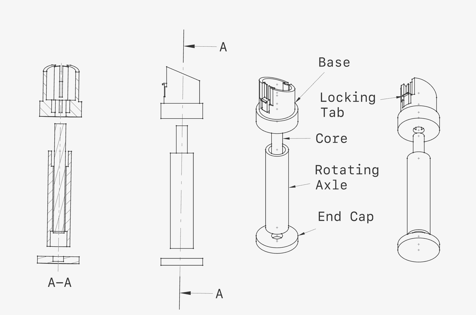
The FRESH spindle has five individual components:
- The base, which holds the spindle in the standard spool holder arm. The base is a printed component;
- The rotating axle, which rotates freely around the core of the spindle, also printed;
- An end cap, glued to the core to keep the spindle together, also printed;
- The core, which work as an axle that runs the whole length of the spindle. The core can be printed or cut from a third party component such as a carbon fiber, steel or aluminum tubes. The third party tubes eliminate the need for post-processing to produce a smooth surface, while providing optimal performance;
- The bearings, connecting the rotating axle with the core, and drastically reducing friction between the rotating axle and the core (which allows the filament roll to rotate with less resistance)
Third party components:
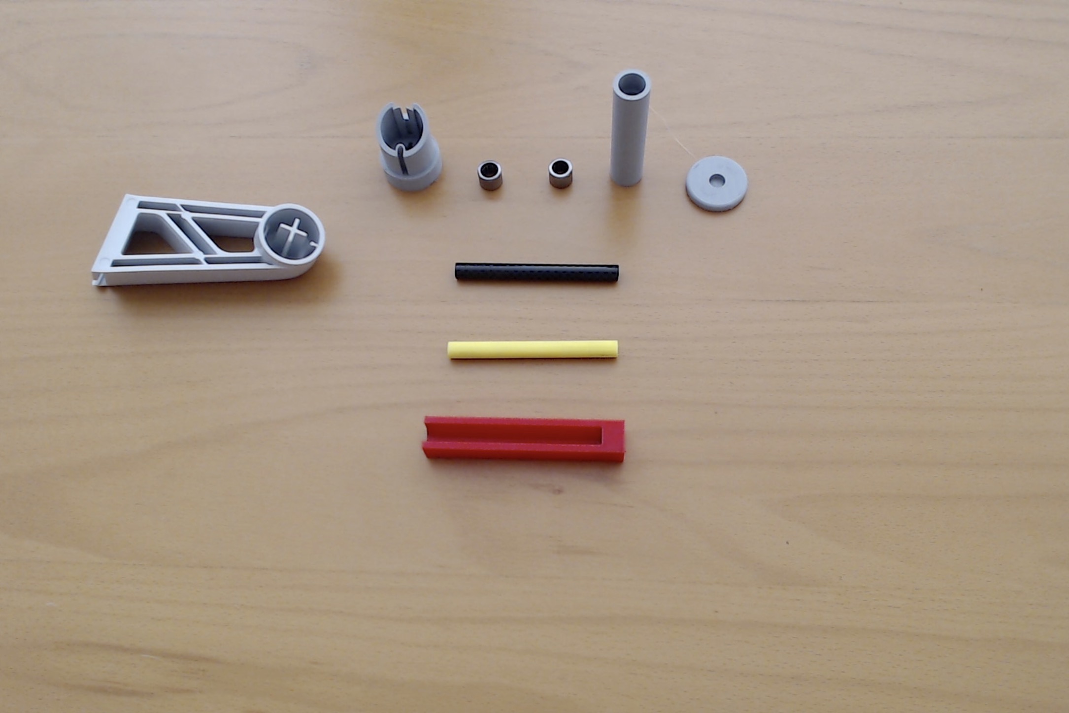
- Required: Two 8x12x10 mm Needle Roller Bearings (i.e., bearings with an 8 mm bore or inside diameter, 12 mm Outside Diameter and 10 mm width). You can find them in Amazon or such, search for ”Needle Roller Bearings 8mm Bore 12mm OD 10mm Width Chrome Steel Open End” to find them;
- Optional: A 79 mm-long 8mm OD rod / tube (the “core”). I had some carbon fiber tubes left-over from a quadcopter project, and it turned out to be perfect for the application, but there are many possible sources. You can search for “8mm OD carbon fiber tube”. There are many to choose from, in both solid form (rods) and hollow (tubes), they all work well; all that matters is that the outside diameter (OD) is 8mm and that the surface is as polished as possible. It can be a tube or a rod, carbon, steel or aluminum
Why carbon rods and needle bearings?
- Carbon fiber tubes/rods are amazingly tough, and can easily overcome the shearing stress of a full filament roll, weighting over a kilogram.If you have 8mm steel tubes (also common in other filament roller designs), you can use them instead, but they are tougher to cut than carbon rods. Finally, you can print your own rod (See note below).
- Needle bearings are amazingly slim. By using these bearings, I was able to design an axle that looks identical to the one being replaced, with the bearings hidden inside it.
Finally, two optional pieces are included:
- A solid cylinder which you can print as the core (in Yellow PETG above), in case that you rather not use a carbon or steel core. In that case, you can print this piece. I have included a simple model that you can use to print with very minimal supports, horizontally oriented, .12 layers, and redundant walls, so that you get maximum shear resistance and as polished a surface as possible. You will need to sand it to make it very smooth, but you will almost certainly add some slight friction to the mechanism.
- A cutting jig that will help you make a cut through either carbon fiber (in Red above), aluminum or steel rods. Precisely because those rods/tubes have very polished (slippery) surfaces, they are hard to mark and cut precisely. By butting the rod against the bottom of the jig, you will have both a secure way to hold it and also a clear measure of 79 mm to use for the cut: now you just need to cut following the open face of the jig.
Documentation (1)
Comment & Rating (18)


