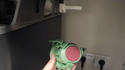
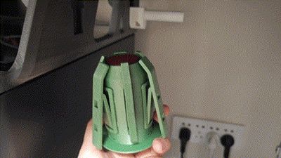
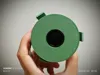
amslite rotary spool holder with auto rewind


Print Profile(4)
Description
ChangeLog
2025-03-17:
As noted in the comments, the central shaft's insertion into the AMS Lite frame was excessively large. This version's central shaft has been revised, incorporating reinforcing ribs to reduce the inner diameter. A hollow cylinder designed to further reduce the inner diameter is also provided; download the STL file as needed. This cylinder’s outer diameter is 0.3mm smaller than the original model's inner diameter, with an inner diameter of 18.4mm. For those who have already printed previous versions, consider printing this revised model or reprinting the central shaft component.
https://github.com/zjoycelee/amslite-rotary-spool/commit/0ac592bcbbbbcb52c93d99bbe0fcb26ac79a1365
AMSLite Rotary Shaft (with Auxiliary Claw System)
This project presents a printable rotary shaft model, including an optional auxiliary claw system, for 3D printers. The rotary shaft helps maintain filament tension during printing, reducing the likelihood of tangling and thus minimizing print failures.
Features and Advantages
- Easy to Print & Print Optimized: This design is optimized for ease of printing, reducing the need for support structures. Sections requiring Z-axis reinforcement have been strategically separated; altering the print orientation yields enhanced strength.
- Auxiliary Claw System: The design incorporates a flexible auxiliary claw system adaptable to various filament spool core diameters, enhancing stability and mitigating the risk of tangling. The auxiliary claw detaches from the housing and mounts to the primary claw, enabling compatibility with larger diameter spools, particularly those with wider core apertures (such as the Jayo brand). This modular system ensures superior stability and minimizes tangling, accommodating spools of varying dimensions.
- Low Cost: Requires only 92 grams of filament, with hardware costs under 1 RMB.
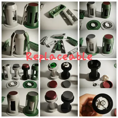
- Replaceable Components: All model components, except the claw assemblies, are replaceable with the original parts.
Required Hardware
This model requires two hardware components for proper operation:
- Three-Wave Washer
- Dimensions: 27mm x 34mm x 0.4mm
- Height: 3.1mm

- Torsion Spring
- Wire Diameter: 0.8mm
- Outer Diameter: 9mm
- Number of Coils: 5
- Rotation Direction: 180-degree left/right rotation

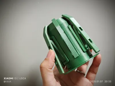
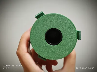
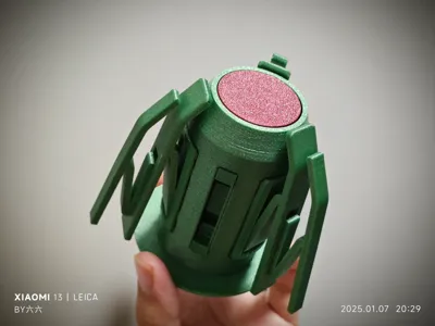
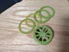
Preview - Rotary Shaft with Auxiliary Claw
Here are previews of the rotary shaft with the auxiliary claw system, including a color-coded diagram illustrating its various configurations.
Original and Combined Configurations

Exploded View

Dynamic Demonstration
Supports Standard Spool Core Diameters
The rotary shaft’s original configuration (auxiliary claw mounted on the housing) is suitable for most filament brands, such as Bambu and Tinmorry.

Supports Large Spool Core Diameters
The combined configuration (auxiliary claw mounted on the primary claw) is designed for spools with larger core diameters, such as the Jayo brand.

User Guide
1. Part Adhesive Assembly
1.1 Potential Part Separation and Adhesive Application Locations
When assembling the separately printed components, adhesive is required in certain areas to ensure a secure bond. Refer to the following sections for adhesive application locations.
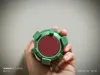
Red areas in the diagrams indicate where adhesive should be applied.
1.1.1 Primary Claw Base
Base and Clip: Apply adhesive to the contact surfaces of the primary claw base and clip to ensure a secure bond.

1.1.2 Green Core
- Clip Components: Apply adhesive to the clip sections of the green core to ensure secure fastening.
- Torsion Spring Center Fixation: Apply adhesive where the torsion spring center contacts the core to ensure secure attachment.
Torsion Spring Short End Fixation: Apply adhesive where the torsion spring short end contacts the core for secure fastening.

1.1.3 Yellow Core
- Clip Components: Apply adhesive to the clip sections of the yellow core to ensure secure fastening.
- Torsion Spring Center Fixation: Apply adhesive where the torsion spring center contacts the core to ensure secure attachment.
- Torsion Spring Short End Fixation: Apply adhesive where the torsion spring short end contacts the core for secure fastening.

1.1.4 Central Shaft
- Circular Rod: Apply adhesive to the contact points of the central shaft’s circular rod and other connecting components.
- Top Washer and Torsion Spring Long End Fixation: Apply adhesive where the top washer contacts the torsion spring’s long end to ensure a secure connection.

1.2 Assembly Steps
- Select Appropriate Adhesive: Use a strong adhesive suitable for plastics or 3D printed parts.
- Apply Adhesive: Apply adhesive evenly to the indicated areas in the diagrams above.
- Assemble Components: Quickly align and firmly press the adhesive-coated components together, ensuring a tight fit with no gaps.
- Allow Adhesive to Cure: Allow the adhesive to cure according to the instructions on the packaging to ensure a strong bond.
1.3 Precautions
- Avoid applying excessive adhesive, as this may cause overflow, affecting appearance or weakening the bond.
- Use a quick-setting adhesive to minimize waiting time and improve assembly efficiency.
- Ensure all components are completely cool before assembly to allow for complete adhesive curing.
- Always work in a well-ventilated area to avoid inhaling adhesive fumes.
- Use protective gloves to avoid direct contact with the adhesive, preventing allergic reactions or skin irritation.
- Use a protective mat or scrap paper to prevent adhesive spills from staining the work surface or other components.
2. Grease Application Locations
Proper lubrication helps ensure smooth operation of the components, reducing friction and wear. Refer to the following sections for grease application locations:
- Apply grease to the contact points between the core and the central shaft to ensure smooth torsion spring operation.
- Apply a moderate amount of grease to the two circular discs where the central shaft contacts the housing to reduce friction.
Blue areas in the diagrams indicate where grease should be applied.
2.1 Central Shaft
The following diagram shows where to apply grease to the central shaft. Apply grease evenly to reduce friction and ensure smooth rotation:

3. Torsion Spring Bending Jig Usage
A torsion spring bending jig can be used to create appropriately shaped torsion springs. Here are the steps for using the torsion spring bending jig:
- Print configurations for the bending templates are provided; select the appropriate plate based on the spring’s desired orientation.
- Prepare the wire for bending and place it in the designated slot on the jig.
- Use an appropriate tool to apply force, bending the wire beyond 90 degrees.
- Cut off the excess wire.
- Continue applying force, bending the wire to nearly 180 degrees.
- Remove the spring from the jig and adjust its shape with pliers.

4. Rotary Shaft Installation
Assuming that parts printed separately have already been assembled using adhesive.
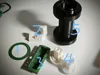
4.1 Prepared Printed Parts

Numbers in the image:
- Housing
- Central Shaft
- Green Core (choose green or yellow as needed)
- Shaft Cap
- Base
- Washer (default 1.2mm thickness, various thicknesses provided)
- Primary Claw Base (*3)
- Primary Claw with Auxiliary Claw Mounting Slot (*3)
- Auxiliary Claw Base (0 / *3)
- Auxiliary Claw (0 / *3) Auxiliary claws are optional; therefore, the quantity is 0 or 3
4.2 Prepared Hardware
- Bent torsion spring
- Three-wave washer

4.3 Installation Steps
Assemble the claw base and claw in the correct order and orientation.
The primary claw base has a small internal protrusion; note the installation direction. Push the primary claw into the claw base; the allowance should allow the claw to be secured in the claw base. If loose, the model has pre-drilled M1.6 screw holes; use M1.6*5 countersunk screws to secure them.

Push the auxiliary claw in flat as shown in the diagram and then pull down.

- Insert the green/yellow core into the central shaft (apply grease to the corresponding locations).
Secure the torsion spring; using the green core as an example:

Install the shaft cap, aligning it with the slot. After pressing down the shaft cap, rotate it to the right.

- Insert the central shaft into the housing (apply grease to the corresponding locations).
Place the washer and then the three-wave washer into the base.

Align the recess at the bottom of the housing with the protrusion on the base; press down on the housing and then rotate it to the right.

Install the primary claw into the corresponding large slot on the housing.

Install the auxiliary claw into the corresponding small slot on the housing (optional).

Design Process
The design of this rotary shaft emphasizes the precise matching and coordination of each component, ensuring all parts are easily printable, maintain good strength, and support filament spools of varying diameters.
1. Core Components (Green and Yellow Versions)
Obtained via original part measurement; can be used as original part replacements. The core components are the heart of the rotary shaft, designed with rotation direction in mind. Green and yellow versions offer different options to suit users' varied feed direction requirements.


For enhanced Z-axis strength and ease of printing, the core has been designed with separated components.

2. Central Shaft Design
Obtained via original part measurement; can be used as original part replacements. The central shaft connects the core to the base and housing, ensuring smooth rotation.

Considering the Z-axis strength and ease of printing, the central shaft has also been designed with separated components.

3. Shaft Cap Design
Obtained via original part measurement; can be used as original part replacements.

4. Base Design
Obtained via original part measurement; can be used as original part replacements. Because the original metal spring clip lacks a universal solution, we've used a three-wave washer. Therefore, the base model differs slightly from the original. To achieve the appropriate frictional force, washers of varying thicknesses are provided for user adjustment.

If the appropriate pressure is uncertain, print washers of different thicknesses for combination testing. For instance, you could print 0.2mm, 0.4mm, and 0.8mm thick washers, yielding seven different thicknesses (0.2mm, 0.4mm, 0.6mm, 0.8mm, 1.0mm, 1.2mm, 1.4mm) through combination.

5. Primary Claw Base Design
Obtained via original part measurement; can be used as original part replacements. The original claw uses a C-shaped spring clip, but lacks a universal solution; hence the use of a Z-shaped spring structure. To ensure a secure connection between the claw and claw base, M1.6 countersunk screw holes have been added.
To increase Z-axis strength, the claw base panel has been thickened, and the clasp has been separated into components.


6. Primary Claw Design
The primary claw’s shape is obtained via original part measurement, ensuring the upper end rests on the housing edge, and the lower end's distance from the housing is verified by measurement. In the original, pressing causes the tail end to rub against the base; the model's tail end length has been slightly reduced.
To provide similar deformation capabilities to the original, a Z-shaped spring structure is employed, with the connection position using a rotating circular path to cooperate with the inner edge of the claw base.

Additionally, to support the auxiliary claw system, two square slots have been added to the primary claw, inspired by pegboard principles.

7. Auxiliary Claw and Auxiliary Claw Base Design
The auxiliary claw is designed to support larger diameter filament spools, requiring quick detachment and support for two configurations. The auxiliary claw uses a Z-shaped spring structure, similar to the primary claw's connection, using a rotating path to interface with the inner edge of the claw base.

The auxiliary claw base design borrows from pegboard principles; the hook-style clasp allows for quick detachment. To increase the connection strength between the auxiliary claw base and the housing, a support plate has been added to the back of the auxiliary claw base to address connection instability caused by deformation.


Design Challenges and Solutions
Challenge 1: Ensuring Print Strength
Due to the nature of 3D printing, Z-axis strength is significantly lower than XY-axis strength. To ensure high-strength rotary shafts, component separation and print orientation optimization were implemented, thereby enhancing Z-axis strength.
Challenge 2: Supporting Different Spool Sizes
To address the challenge of supporting spools of varying diameters, an auxiliary claw system was designed. Auxiliary claws can be printed as needed and quickly detached from the housing and attached to the primary claw, ensuring the rotary shaft accommodates filament spools of diverse dimensions.
I have also created other models in this rotary shaft series; please feel free to explore them:
| amslite rotary spool holder relevant models | pictures | cn-link | global-link |
| BambuStyle Rotary Spool Holder | | https://makerworld.com.cn/zh/models/839089#profileId-824478
| https://makerworld.com/en/models/996580#profileId-973060
|
| Universal Rotary Spool Holder |   | https://makerworld.com.cn/zh/my/models/878953/
| https://makerworld.com/en/models/1040576#profileId-1025386
|
| amslite rotary spool holder cap with numbers | amslite Turntable Rack spool rotary rotary spool spool holder amslite spool rotary spool holder rewind Spool Rack Installation bmcu yba LicenseThis user content is licensed under a Standard Digital File License. You shall not share, sub-license, sell, rent, host, transfer, or distribute in any way the digital or 3D printed versions of this object, nor any other derivative work of this object in its digital or physical format (including - but not limited to - remixes of this object, and hosting on other digital platforms). The objects may not be used without permission in any way whatsoever in which you charge money, or collect fees. Related Models |
Comment & Rating (106)