AMS lite Universal Rotating Shaft, Secure Spool, One Size Fits All


Print Profile(3)

Description
ChangeLog
2025-03-17:
Following community feedback regarding excessive central shaft protrusion into the AMS Lite frame, this version incorporates a reinforced central shaft with a reduced inner diameter. A hollow cylinder STL is also provided for those who wish to further reduce the inner diameter. This cylinder's outer diameter is 0.3mm smaller than the original model's inner diameter, with an inner diameter of 18.4mm. Users with previously printed versions may consider printing this revised model or reprinting the central shaft component.
https://github.com/zjoycelee/amslite-rotary-spool/commit/0ac592bcbbbbcb52c93d99bbe0fcb26ac79a1365
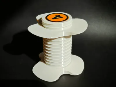
AMSLite Universal Rotary Shaft
This project offers a more versatile rotary shaft model compatible with AMS Lite. The rotary shaft maintains filament tension during printing, mitigating the risk of tangling and print failures. This model retains the core functionality of the original Bambu Lab rotary shaft and is compatible with the AMS Lite fixed shaft (18mm diameter).
Observations during use of the original rotary shaft revealed several drawbacks:
- The absence of metal components in the claw assembly leads to fatigue and reduced resilience over time.
- The original design minimally supports 52mm spool bores.
- The original design presents a risk of spool slippage and dropping.
Therefore, referencing the securement method from the rice bucket era and integrating rotary shaft principles, this version utilizes a screw and nut mechanism for spool fixation. While filament changes are slightly slower compared to the original's elastic claw system, the nut secures the spool, preventing drops and eliminating plastic component fatigue. Aesthetically, it admittedly lacks the appeal of the original design.
However, considering the advantages, I strongly recommend this universal version.
Features and Advantages
- Ease of Printing & Optimized Print Settings
This design is optimized for easy printing, minimizing support structures and enhancing Z-axis strength. Altering the print orientation yields even greater strength. - Broad Spool Compatibility
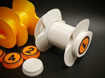
The screw section diameter is 40.69mm, the nut's maximum diameter is 80mm, and the screw length is 75mm, accommodating most 200g, 250g, and 1kg spools. - Low Cost
This design is highly cost-effective, requiring only 59 grams of filament and less than 1 Chinese Yuan in hardware costs. - Fast Print Speed
Printing is completed in approximately 2.5 hours. - Compatibility with Original Fixed Shaft
The core component is available in yellow and green, matching the original's inner diameter and height, thus ensuring compatibility with the original fixed shaft and the original AMS Lite.
Boost Me (for free)
If you appreciate my design, please consider boosting me. Boosting is free, yet it significantly aids my future creations. Thank you for your support!
I've developed other models in this rotary shaft series; please explore further:
| amslite rotary spool holder relevant models | pictures | cn-link | global-link |
| BambuStyle Rotary Spool Holder |   | https://makerworld.com.cn/zh/models/839089#profileId-824478
| https://makerworld.com/en/models/996580#profileId-973060
|
| Universal Rotary Spool Holder |   | https://makerworld.com.cn/zh/my/models/878953/
| https://makerworld.com/en/models/1040576#profileId-1025386
|
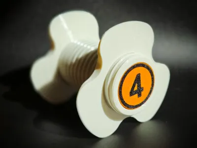
| amslite rotary spool holder cap with numbers |  | https://makerworld.com.cn/zh/models/878898#profileId-87384 | https://makerworld.com/en/models/1040524#profileId-1025327 |
direction adjustable core part for amslite |  | https://makerworld.com.cn/zh/models/728157#profileId-685744
| https://makerworld.com/en/models/876933#profileId-830130
|
| Holder for ams riser v2 |  | https://makerworld.com.cn/zh/models/726091#profileId-692363
| https://makerworld.com/en/models/874637#profileId-836934
|
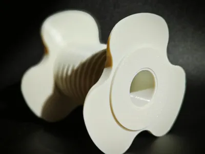
Preview - Universal Rotary Shaft
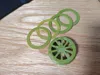
Rendered Image Preview

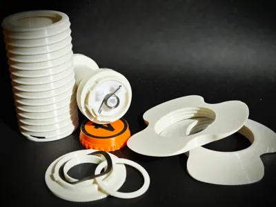
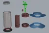
Exploded View

Required Hardware
This model requires the following two hardware components for proper operation:
- Three-Wave Washer
- Dimensions: 25mm x 31mm x 0.4mm
- Height: 2.9mm

- Torsion Spring
- Wire Diameter: 0.8mm
- Outer Diameter: 9mm
- Rotation Direction: 180° Left/Right
- Number of Coils: 5

User Guide
This user guide provides detailed instructions and precautions to facilitate a smooth operational experience.
1. Part Adhesive Assembly
1.1 Potential Parts and Adhesive Application Locations
During part assembly, adhesive application is required in certain areas to ensure secure bonding. Refer to the following sections for adhesive application locations.
Red areas in the diagrams indicate adhesive application points.
1.1.1 Green Core
- Clamp Components: Apply adhesive to the clamp sections of the green core to ensure secure attachment.
- Torsion Spring Center Fixation: Apply adhesive where the torsion spring center contacts the core.
Torsion Spring Short End Fixation: Apply adhesive where the short end of the torsion spring contacts the core to ensure secure fastening.

1.1.2 Yellow Core
- Clamp Components: Apply adhesive to the clamp sections of the yellow core to ensure secure attachment.
- Torsion Spring Center Fixation: Apply adhesive where the torsion spring center contacts the core.
Torsion Spring Short End Fixation: Apply adhesive where the short end of the torsion spring contacts the core to ensure secure fastening.

1.1.3 Central Shaft
- Circular Rod: Apply adhesive to the contact points between the central shaft's circular rod and other connecting components.
Top Washer and Torsion Spring Long End Fixation: Apply adhesive where the top washer and the long end of the torsion spring meet to ensure a robust connection.

1.2 Assembly Steps
- Select Appropriate Adhesive: Use a strong adhesive suitable for plastics or 3D printed parts.
- Apply Adhesive: Evenly apply adhesive to the indicated areas shown in the diagrams above.
- Assemble Components: Quickly align and firmly press together the adhesive-coated parts, ensuring a tight fit without gaps.
- Allow Adhesive to Cure: Allow the adhesive to cure according to the package instructions to ensure secure bonding.
1.3 Precautions
- Avoid excessive adhesive application to prevent overflow, affecting aesthetics or compromising bonding strength.
- Use quick-drying adhesive to minimize waiting time and improve assembly efficiency.
- Ensure all components are fully cooled before assembly to guarantee complete adhesive curing.
- Always work in a well-ventilated area to avoid inhaling adhesive fumes.
- Use protective gloves to prevent direct contact with the adhesive, preventing allergic reactions or skin irritation.
- Use a protective mat or scrap paper to prevent adhesive spills from contaminating work surfaces or other components.
2. Grease Application Locations
Proper lubrication ensures smooth component operation, reducing friction and wear. Refer to the following sections to identify grease application points:
- Apply grease to the contact points between the core and the central shaft for smooth torsion spring operation.
- Apply a small amount of grease to the two circular discs where the central shaft contacts the housing, reducing friction.
Blue areas in the diagrams indicate grease application points.
2.1 Central Shaft
The diagram below illustrates the grease application locations on the central shaft. Apply grease evenly to reduce friction and ensure smooth rotation:

3. Torsion Spring Jig Usage
A torsion spring bending jig facilitates the creation of appropriately shaped springs. The following steps outline the jig's use:
- Print configurations for the bending templates are provided; select the appropriate plate based on the spring's orientation.
- Prepare the spring wire and insert it into the jig's designated slot.
- Using an appropriate tool, apply force to bend the wire beyond 90 degrees.
- Cut off any excess wire.
- Continue applying force to bend the wire to approximately 180 degrees.
- Remove the spring from the jig and adjust its shape with pliers.

4. Rotary Shaft Installation
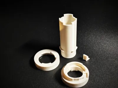
Prepared Printed Parts

Numbered components in the image:
- Housing
- Housing Support (remove)
- Shaft Cap
- Base
- Washer (default 1.2mm thickness, various thicknesses provided)
- Green Core (choose green or yellow as needed)
- Central Shaft
- Spool Locking Nut (8mm height, 80mm maximum outer diameter)
Prepared Hardware
- Bent Torsion Spring
Three-Wave Washer M25*31mm

Installation Steps
- Insert the green/yellow core into the central shaft (apply grease to the contact points).
Secure the torsion spring (using green as an example):

Install the shaft cap, aligning it with the slot. Press and rotate the shaft cap clockwise.

- Insert the central shaft into the housing (apply grease to the contact points).
Place the washer and then the three-wave washer onto the base.

Align the recess at the bottom of the housing with the protrusion on the base. Press and rotate the housing clockwise.

Attach a spool nut to the housing. After inserting the spool, attach the second nut, noting the tapered direction. Tighten after spool installation.
License
You shall not share, sub-license, sell, rent, host, transfer, or distribute in any way the digital or 3D printed versions of this object, nor any other derivative work of this object in its digital or physical format (including - but not limited to - remixes of this object, and hosting on other digital platforms). The objects may not be used without permission in any way whatsoever in which you charge money, or collect fees.
Comment & Rating (25)