
V-Spooler 1.0 Linear Rail Upgrade

Print Profile(1)

Bill of Materials


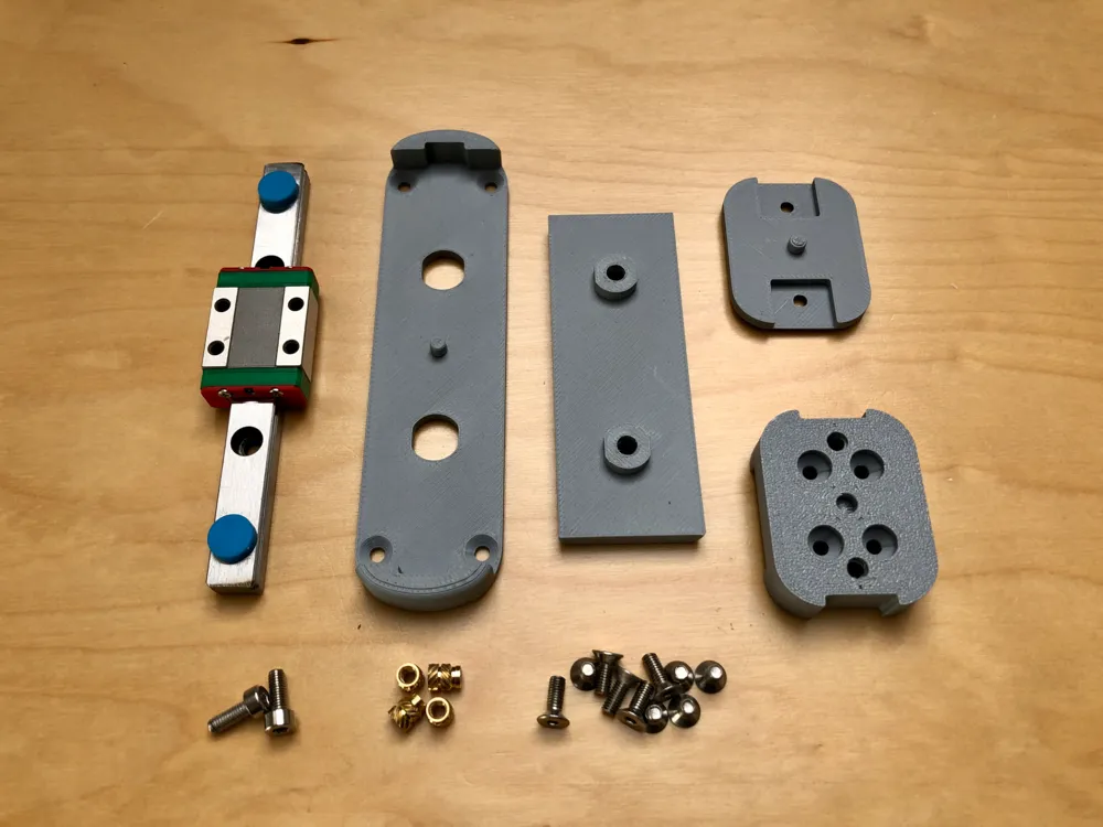
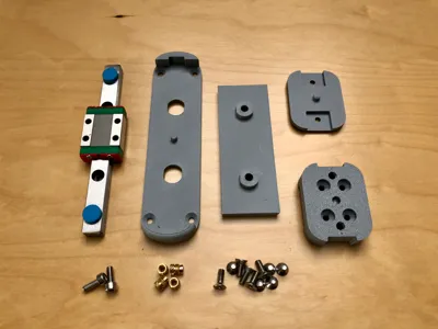
- LML9B Miniature Linear Rail 100mm x 1:
- M3x5.7 Brass Heat Inserts x 4:
Description
Linear Rail Upgrade for V-Spooler 1.0
This upgrade is brought to you by kind permission of Fyrby Additive the V-Spooler Designer
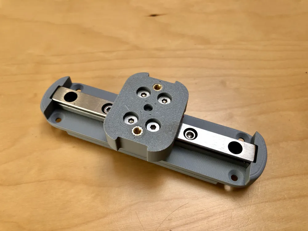
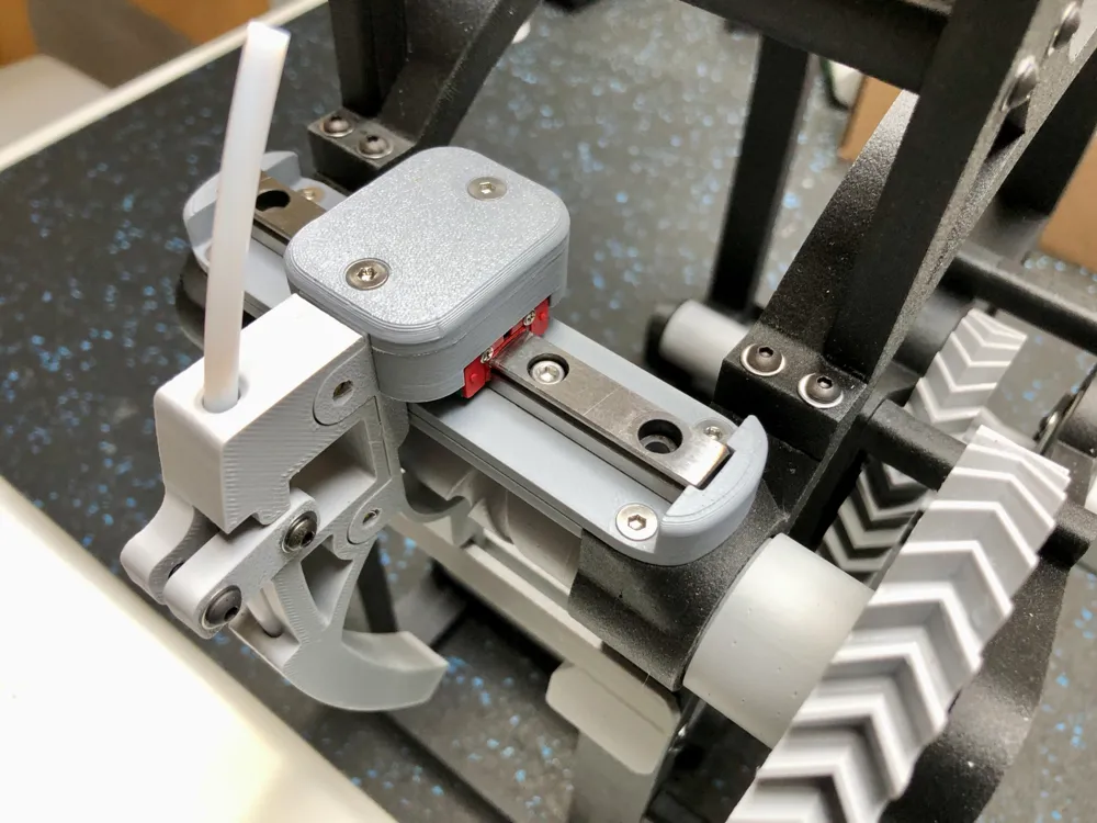
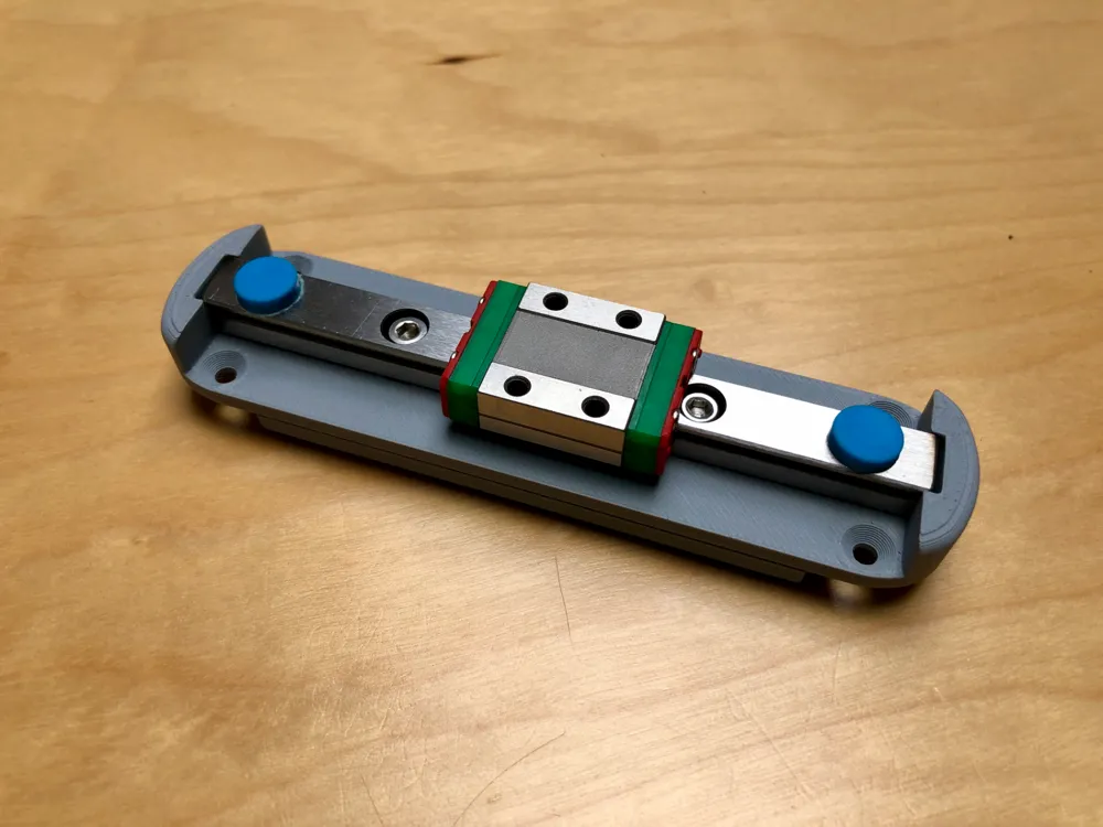
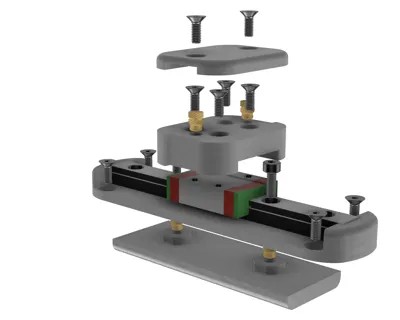
This upgrade replaces the existing Cam Follower Balancer and Bearings with a 100mm miniature Linear Rail. This provides a very stable platform for the moving part and eliminates both vertical and transverse play from the set-up. The smooth stable movement is particularly helpful when operating the V-Spooler at increased speeds with either a dedicated electric motor or a cordless drill.
Linear Rail readily available on Amazon https://www.amazon.co.uk/Linear-Guide-Rail-Carriage-Miniature/dp/B084HGBZL6
This upgrade can be installed with minimum disassembly of the V-Spooler. Only two printed parts need to be replaced.
Assembly Instructions
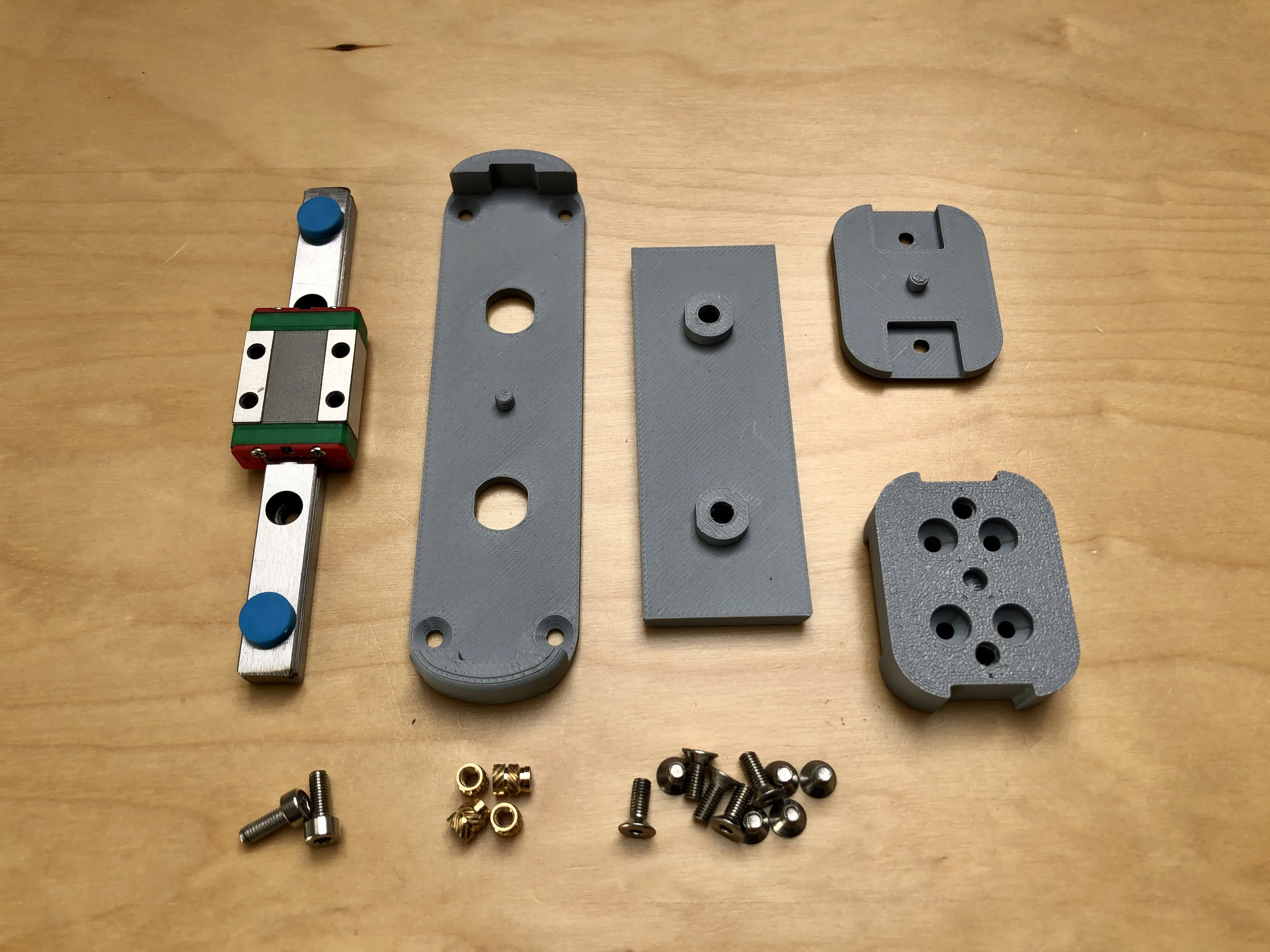 | Print parts and assemble hardware |
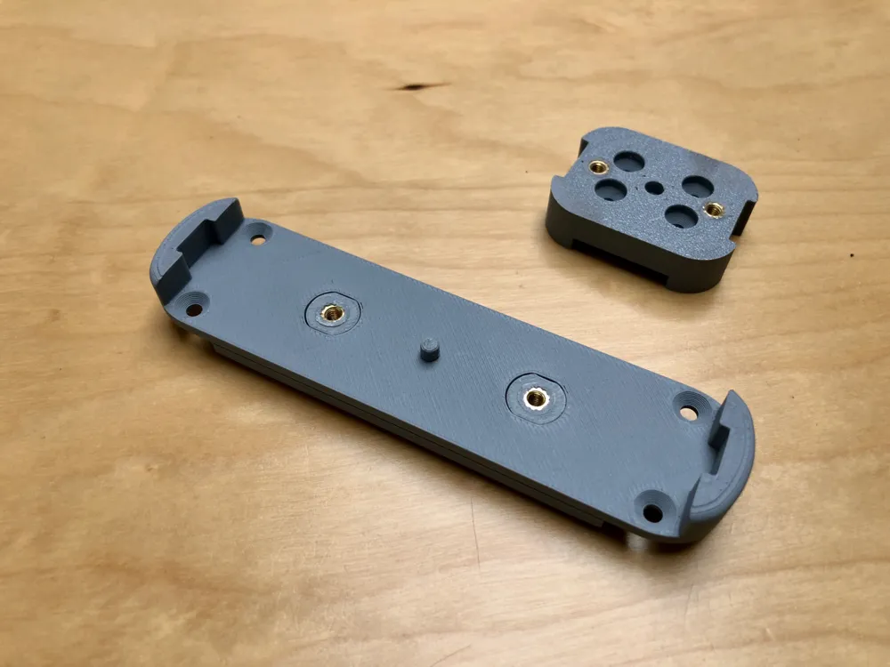
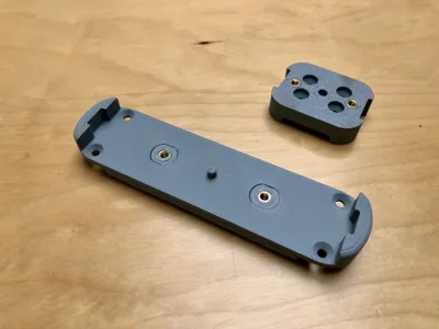
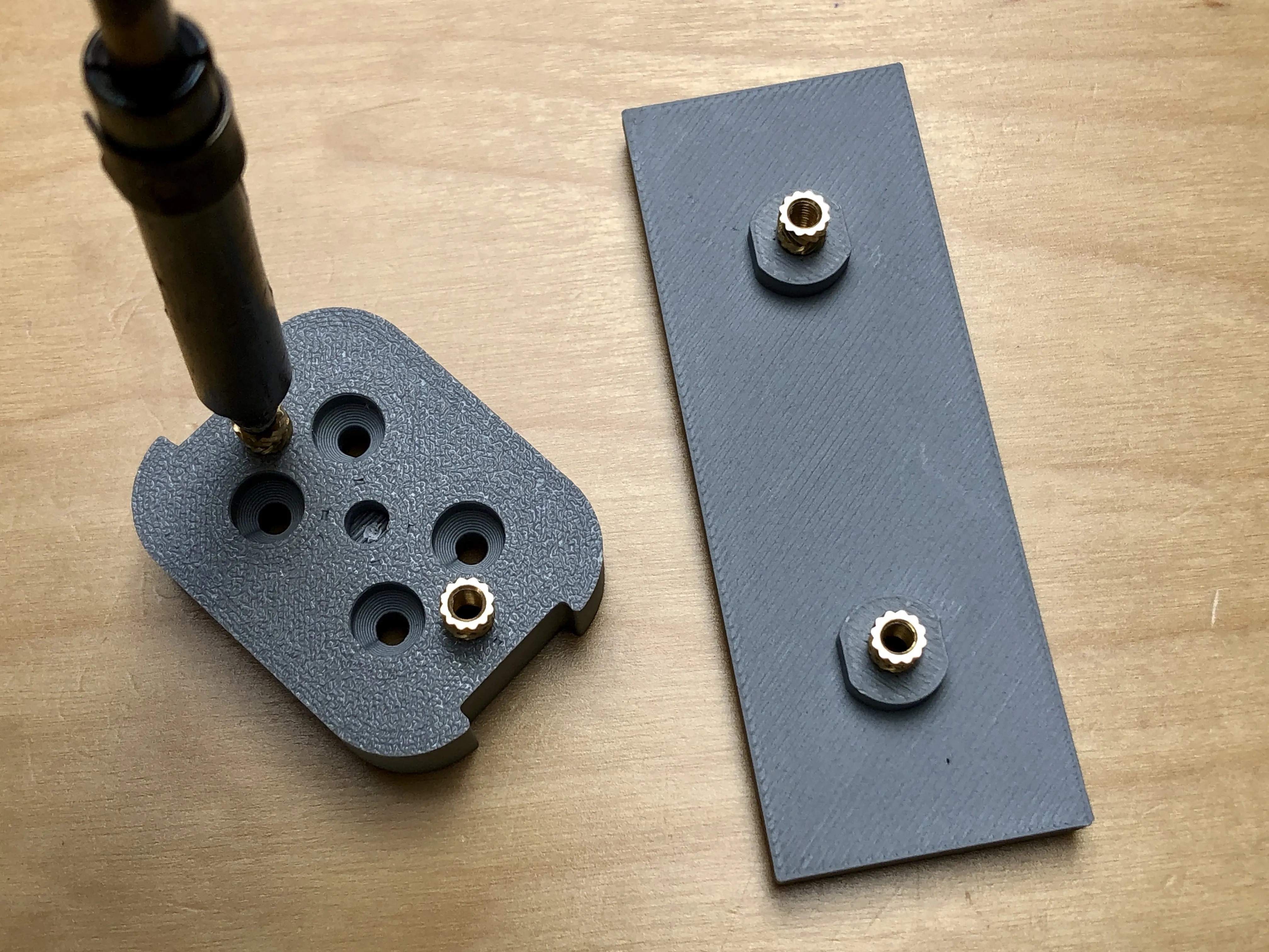 | Set the four M3 brass inserts with a soldering iron in the Cam Balancer Base and Slide Carrier as shown
Ensure the brass inserts are flush with surface and trim away any excess plastic |
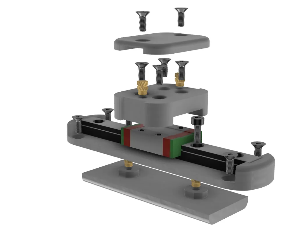
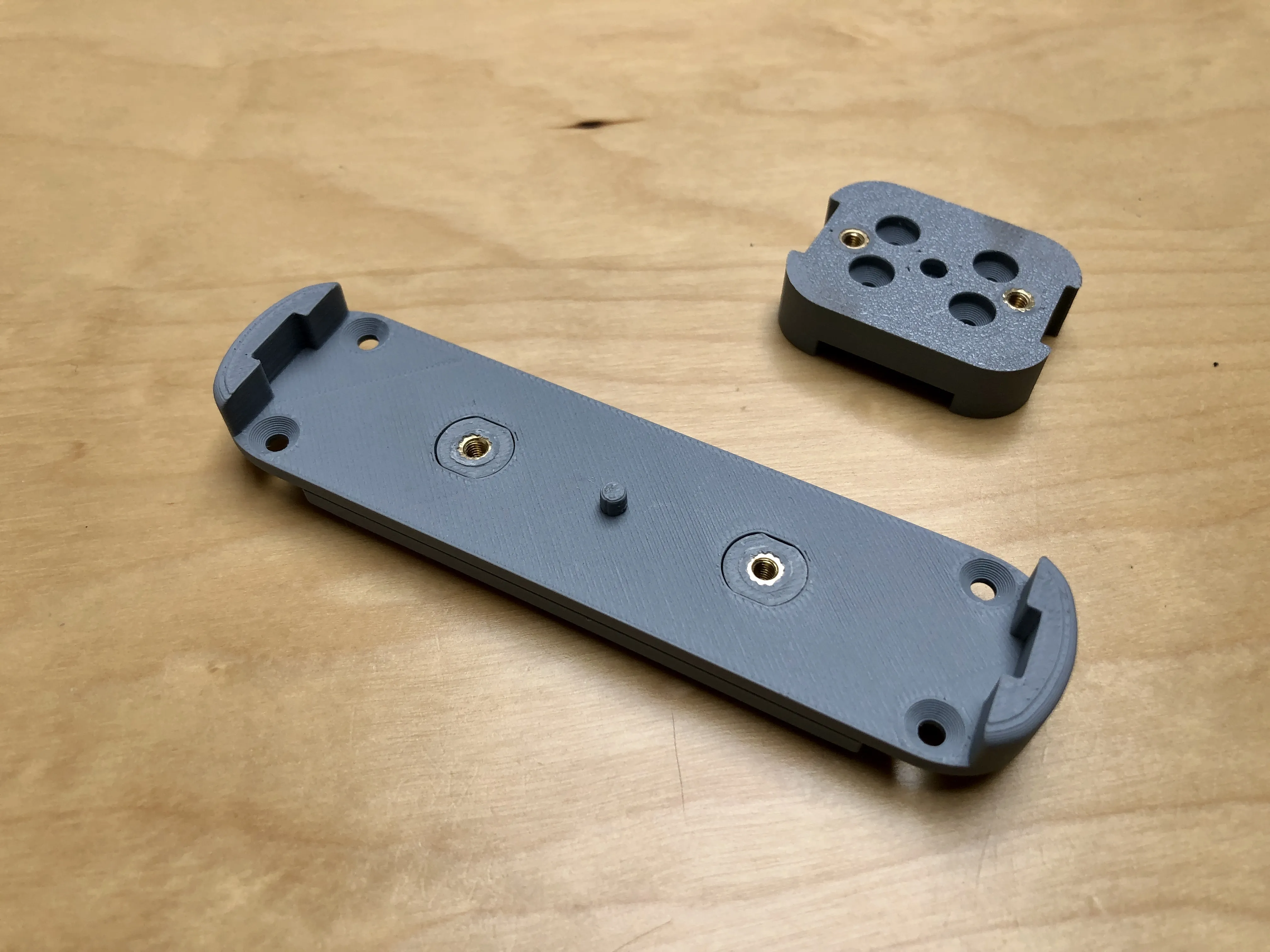 | Assemble the Cam Balancer Base to the Cam Balancer Top |
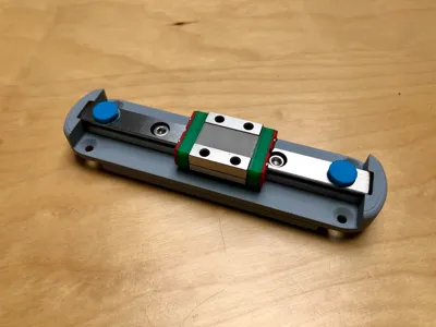
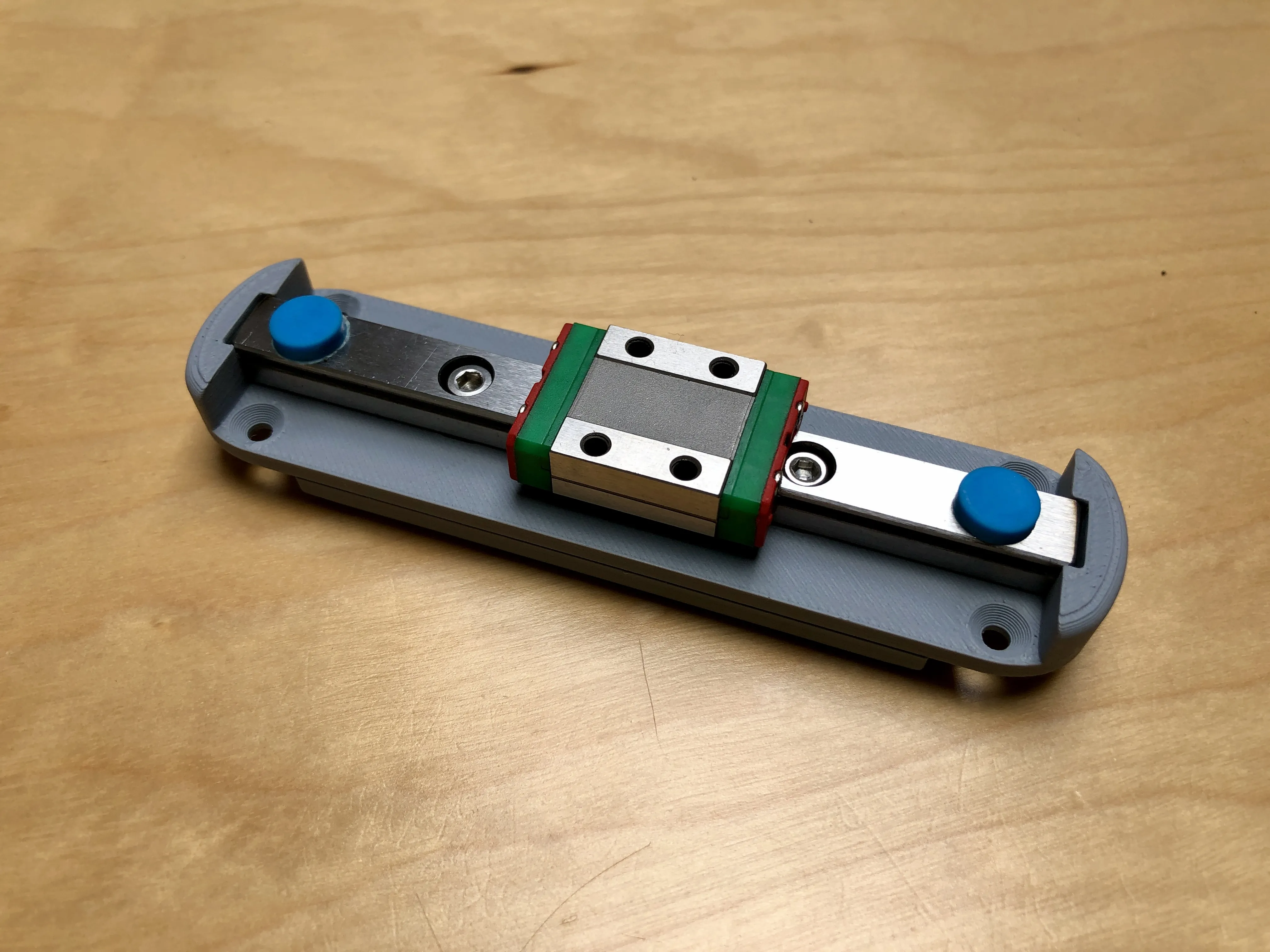 | Insert the 100mm LML9B linear rail into the printed part and secure with two M3x8 Socket Head Cap Machine Screws (SHCS)
Leave the blue stops in place until the rail is secured to prevent the carriage sliding of the end of the rail. |
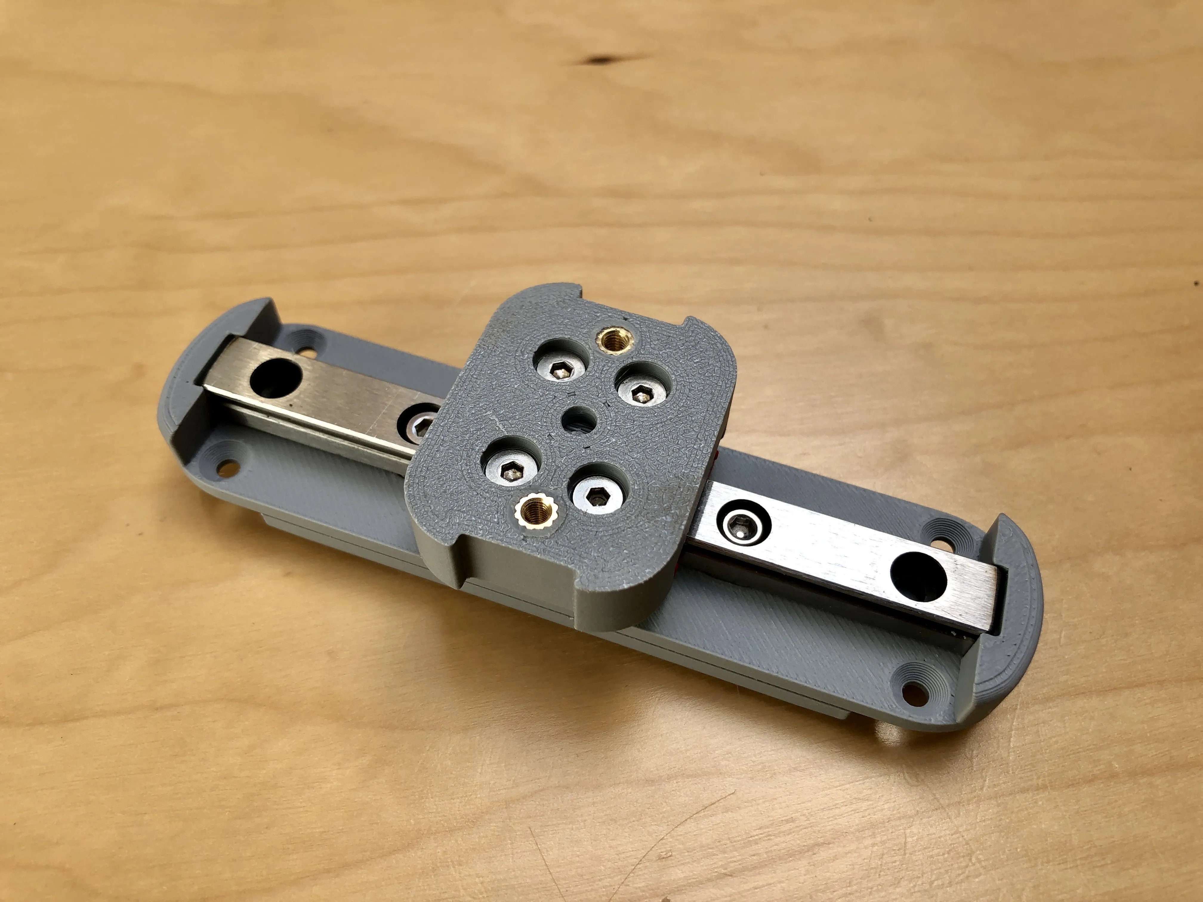 | Position the Slide Carrier on the carriage and secure with four M3x8 Flat Head Cap Machine Screws (CSK) |
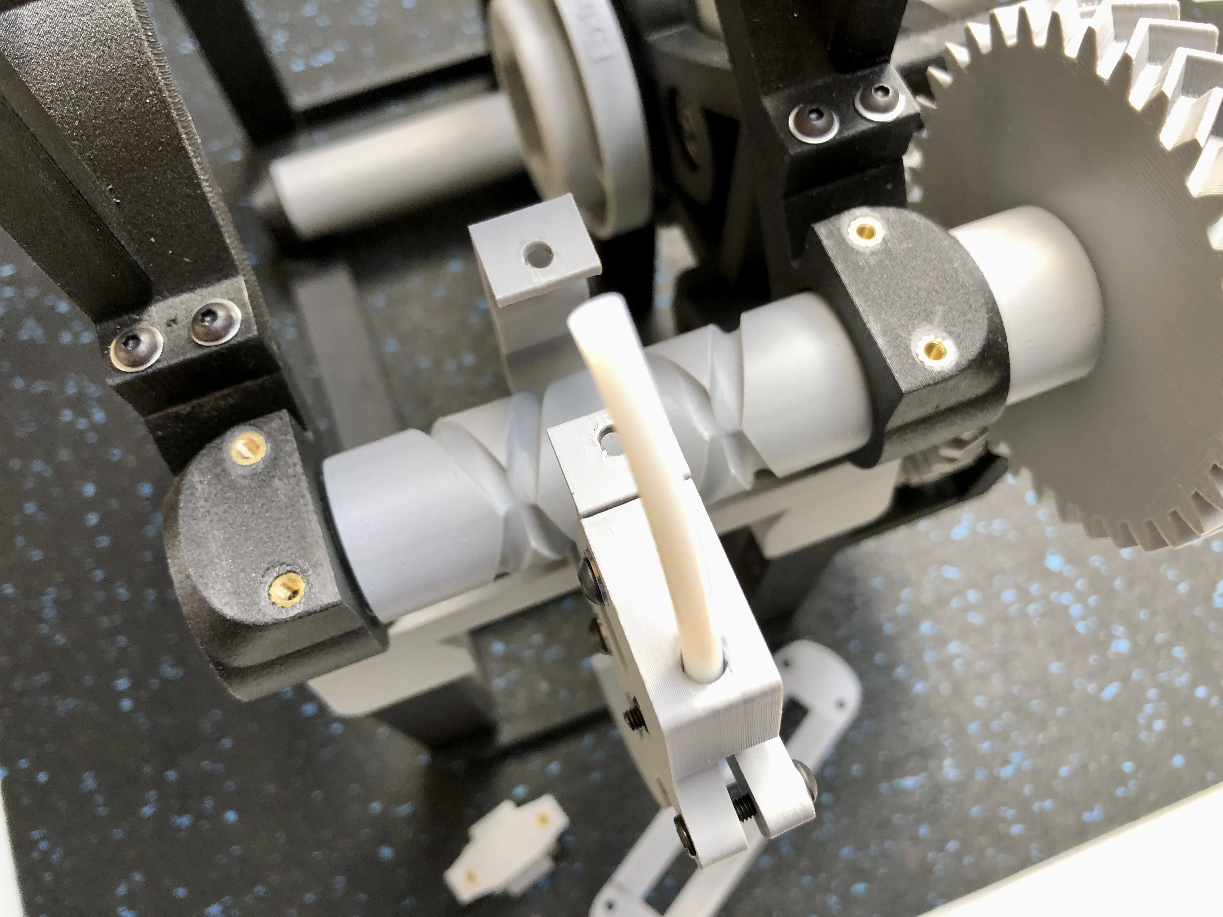 | Remove the existing Cam Balancer and Carrier Top from the V-Spooler |
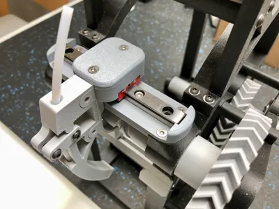
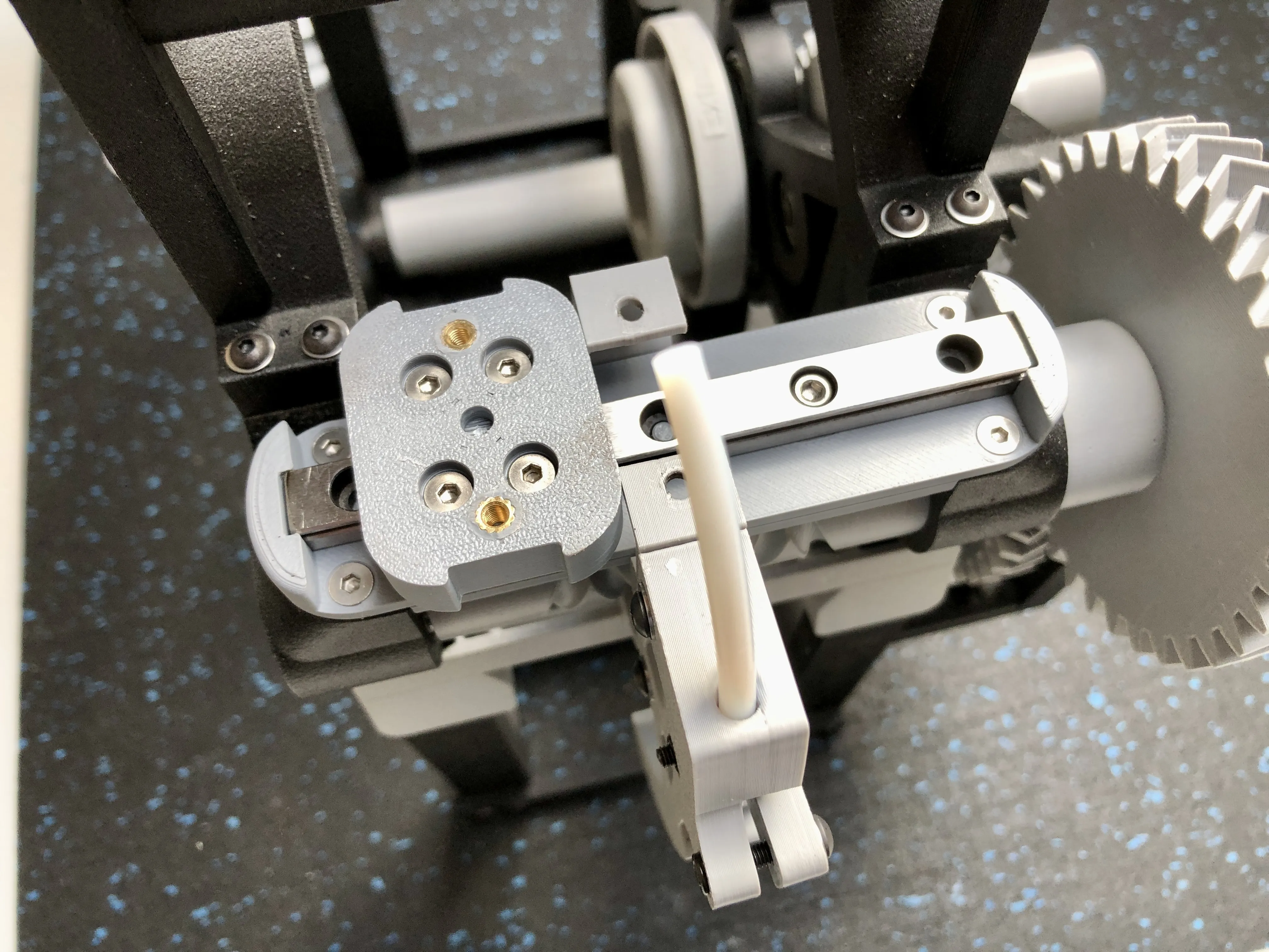 | Position the new assembly and secure with four M3x8 Flat Head Machine Screws (CSK) screws
Please note that Flat Head screws are required here to ensure clearance with the underside of the sliding carriage |
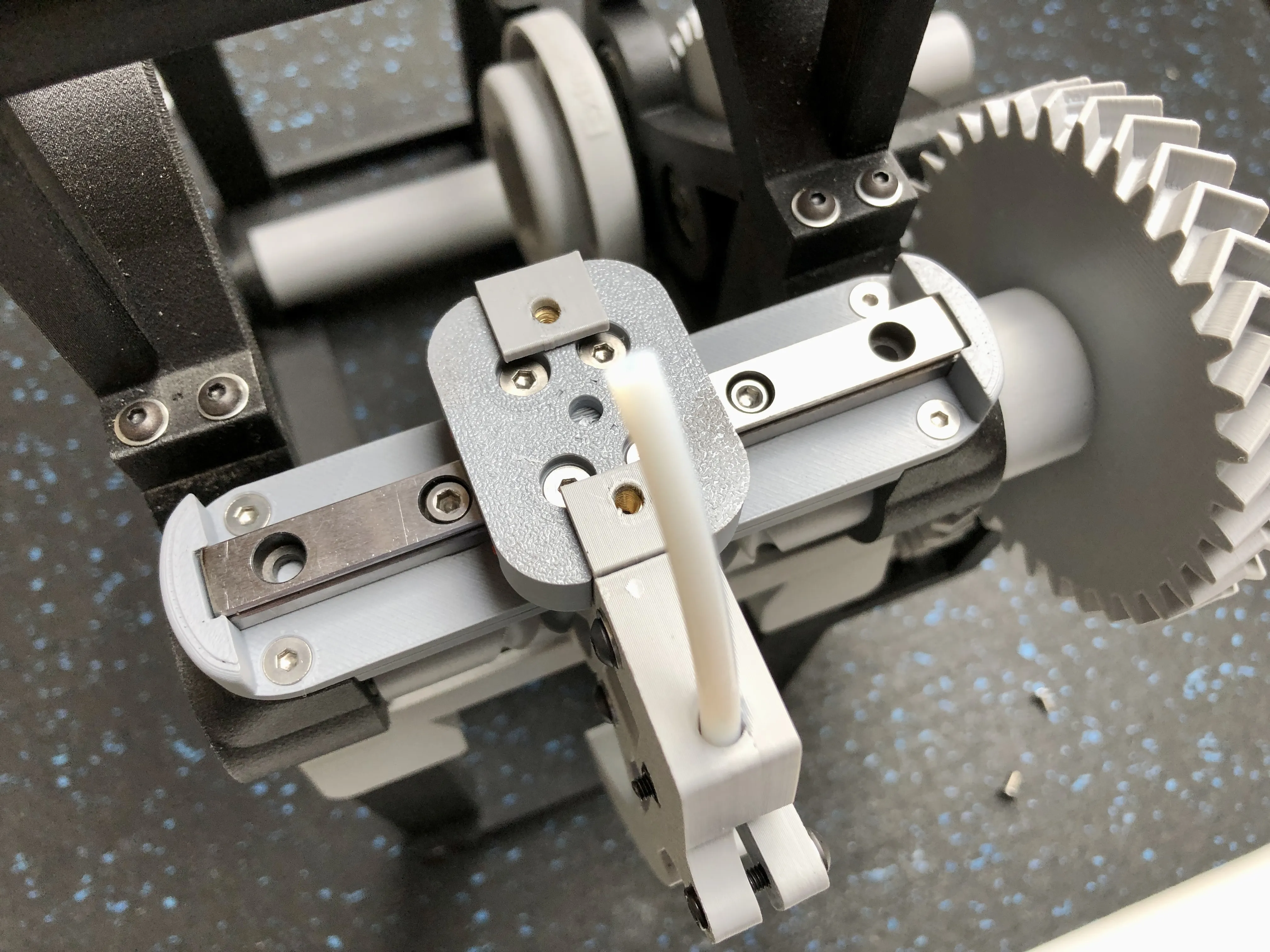 | Lift the existing Carrier slightly and slide the carriage into position locating the Carrier legs in the cut-outs in the Sliding Carrier |
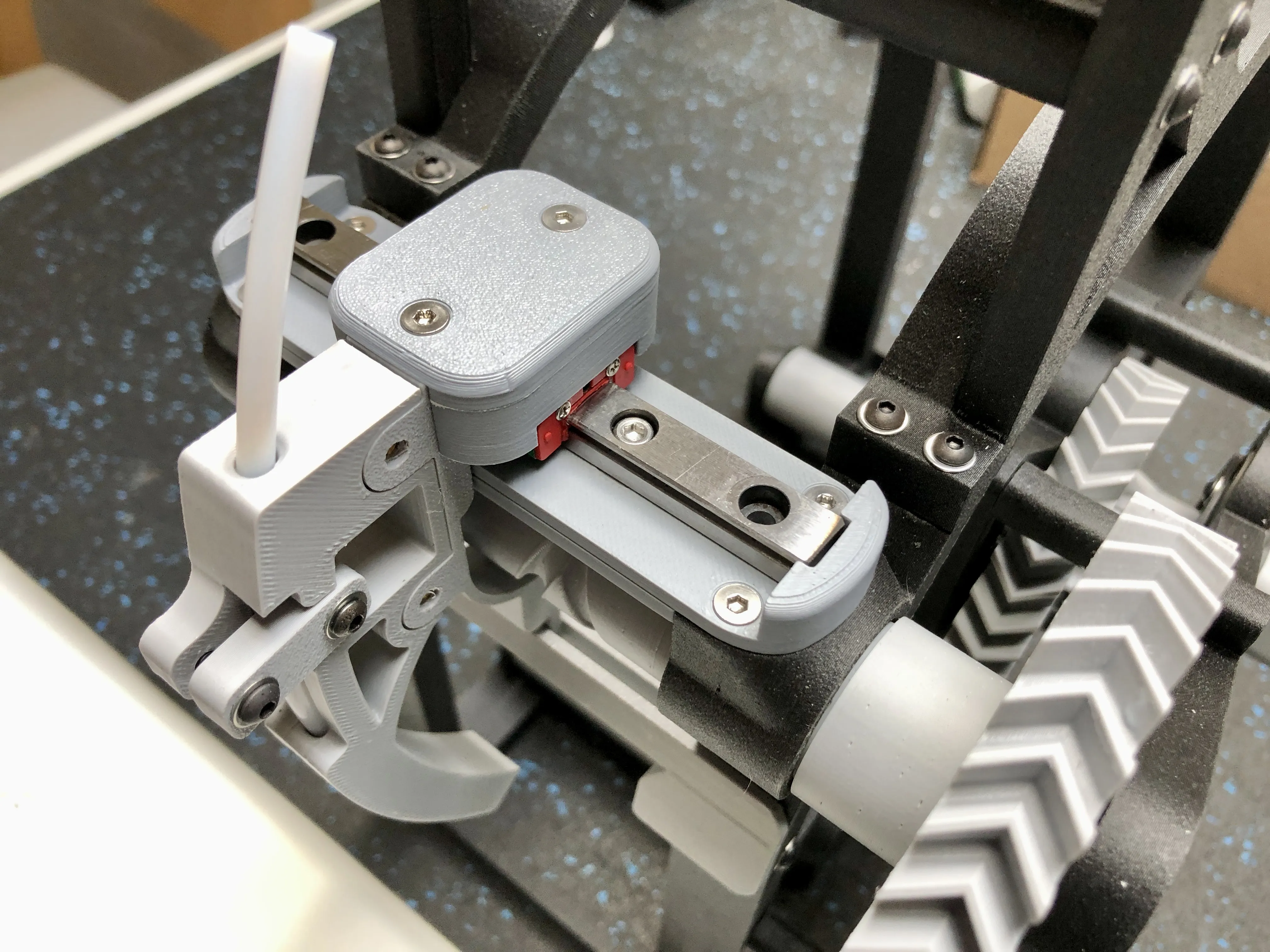 | Position the Cap over the Carrier and secure with two M3x8 Flat Head Machine Screws (CSK)
Run the V-Spooler and test for smooth action. |
Documentation (1)
License

You shall not share, sub-license, sell, rent, host, transfer, or distribute in any way the digital or 3D printed versions of this object, nor any other derivative work of this object in its digital or physical format (including - but not limited to - remixes of this object, and hosting on other digital platforms). The objects may not be used without permission in any way whatsoever in which you charge money, or collect fees.


Comment & Rating (201)