EASY TOLERANCE UNDERSTANDING AND TESTS


Print Profile(1)

Description

Let me first of all say that these considerations should not be taken as "the absolute truth and the ultimate solution" for all cases of tolerance in 3D printing, but they are intended to be a help for those who approach this nice world of 3dprinting to obtain, create , develop models that are as functional as possible. I am aware that among you there are people who are more expert than I am and, for this reason, any intervention you make will be taken into consideration and will help the whole community.
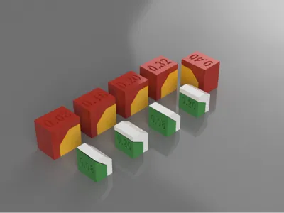
This model is made up of several separate blocks which, in case of a sufficient calibration of your printer, should respond to the solutions mentioned below.
The blocks have tolerances of 0.08,0.16, 0.20, 0.32 and 0.40 mm, i.e. all multiples of the layer presets 0.08 FINE and 0.20 STANDARD for a nozzle of 0.4 mm. Each block has a vertical separation, a 45° separation and a horizontal separation (theoretically in order from easiest to most difficult).
I have had confirmation that many times the characteristics that we are assigning to the printing possibilities at the time of slicing and sending to print are not taken into account.
Much, or rather everything, depends on the consistent choice of the height of the layer to use (I remember that there are methods to adapt the layers during printing but this is another matter that we will not take into consideration).
In fact, let's consider the case of having a separation of two blocks of 0.16mm both vertically and horizontally. Well we must absolutely keep this in mind: Horizontal spacings are (more or less) all possible while vertical separations are not.
In fact, if the slicer is set to use 0.20 layers, in this case the separation will not occur and the layers will be merged (as you can see from the image at point "A").
We should therefore use a layer setting between 0.08 and 0.16... simple, right?
In this picture the B separations (0.16mm and 0.20mm Will both be 0.20mm) . While the separation in point c (0.32 and 0.40 ) will both be 0.40mm.

Now if we still use our 0.20 layers and we come across a vertical separation of, for example, 0.32 then our slicer will only leave a gap of 0.20 mm as it cannot move multiples that would give us that precise distance (points B and c in the picture). We would therefore need to set the layers to 0.08 or 0.16 to obtain a distance of 0.32.
In this picture the B separations (0.16mm and 0.20mm Will both be 0.16mm) . While the separation in point c (0.32 and 0.40 bot multiple of 0.08) can be precisely calculated.

In summary, using a 0.20mm layer setting we can obtain vertical separations of 0.20,0.40,0.60mm. and so on.... all intermediate separations will be assimilated to multiples of 0.20.
This means that by choosing a setting of 0.08 mm we can obtain vertical separations of 0.08, 0.16,0.24,0.32 mm and so on...
Let's now move on to angles in the case of separations to obtain a mechanical movement or a simple division…
Our printers work as you well know with "FILAMENT DEPOSIT", that is, a plastic filament is melted and extracted from a nozzle to be deposited on a surface or on a previously extruded filament…
What happens if, under the filament being deposited, there was a vacuum?
Well yes, the filament falls and does not hold its position until it has cooled down.
So we need to make sure of one of the following two cases:
- The extruding filament is supported by a layer beneath it
- The vacuum underneath the extruding filament is enough to prevent it from melting, and this also depends a lot on the cooling capacity and the speed with which the overhanging is taking place. If the space is too narrow then the tolerance would be cancelled, if the distance is too much, on the contrary, we could experience a distortion of the thread with consequent inability to free the piece.
Let's examine the photos here:
 |  |
 | 
|
- In the first spot the picture shows a 0.20 layers slicing: at 45° the filament has enough support underneath to not fall and therefore we would hardly have a loss of tolerance although the filament itself has its own weight and can slightly deform risking getting too close to the opposite wall
- In the second spot we are using 0.08 layers for a 45° slope: The situation is optimal. The layers are thin and the support base is very consistent. the weight is relatively microscopic and there is no possibility of loss of tolerance.
- Third spot: 60° and 0,08 layers: The situation becomes complicated. the support surface of the filament is poor, the edge could bend or slip and come dangerously close to the opposite wall. There is a good chance that the tolerance will be almost completely eliminated but the cooling during extrusion could allow the piece to detach anyway…
- Fourth spot: 60° slope and 0.20mm layers height: in this case the filament has no support surface and is certainly destined to slip and bend, probably sticking to the opposite wall and making the tolerance useless. The thickness of 0.20, although standard, begins to take longer to cool and can transmit its heat to the filament on which it rests, thus causing unpleasant deformations.
It will require considerable forcing of the piece to try to detach it with the very high risk of not succeeding and compromising the whole integrity of the model.
As you can see, there are countless variables and situations to study when, with our filament deposit printers, we want to create tolerance margins to make our models functional.
- The layer height, speed and cooling, elements that can also be adjusted and chosen in the slicers, as well as having to be well exploited by the printer itself and the quality of its components.
- The consistency, dryness, elasticity of the filament and its non-expansion capacity.
- And, obviously, during the design phase, avoid where possible excessively large angles and a well-calibrated tolerance (neither too little nor too large).
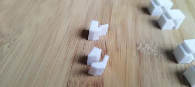
Here a some picture of a printing i did:
 An overview of the pieces… |  The 60° at 0.20 height broke, at 0.08 I detached (with efforts!!) |
 0.16 and 0.20 tolerance resulted the same (layers 0.20) no difficulties to detach… |  A 0.08mm separation can't be obtained whiile using 0.20 layers. the piece is completely stitched. |
 At 0.20mm layers they was both considered as separated by 0.40 mm. The most easy separation (they came away alone from the built plate). |
I hope that these little explanations and humble advice have been and will be of help to you.
Print these small blocks using different layers and post your results.. As usual, don't forget to mention your printer, the filament used and the details relating to the height of the layers.
And if you have any further advice, for the good of the whole community (and mine lol) don't hesitate to share them!
SEE YOU SOON MATES !!!!
…Take a look at my other models…
 |  |  |  |
 |  |  |  |
 |  |  |  |
License
You shall not share, sub-license, sell, rent, host, transfer, or distribute in any way the digital or 3D printed versions of this object, nor any other derivative work of this object in its digital or physical format (including - but not limited to - remixes of this object, and hosting on other digital platforms). The objects may not be used without permission in any way whatsoever in which you charge money, or collect fees.
Comment & Rating (2)