
Easy Electronics alternative for LTS Respooler


Print Profile(1)


Description
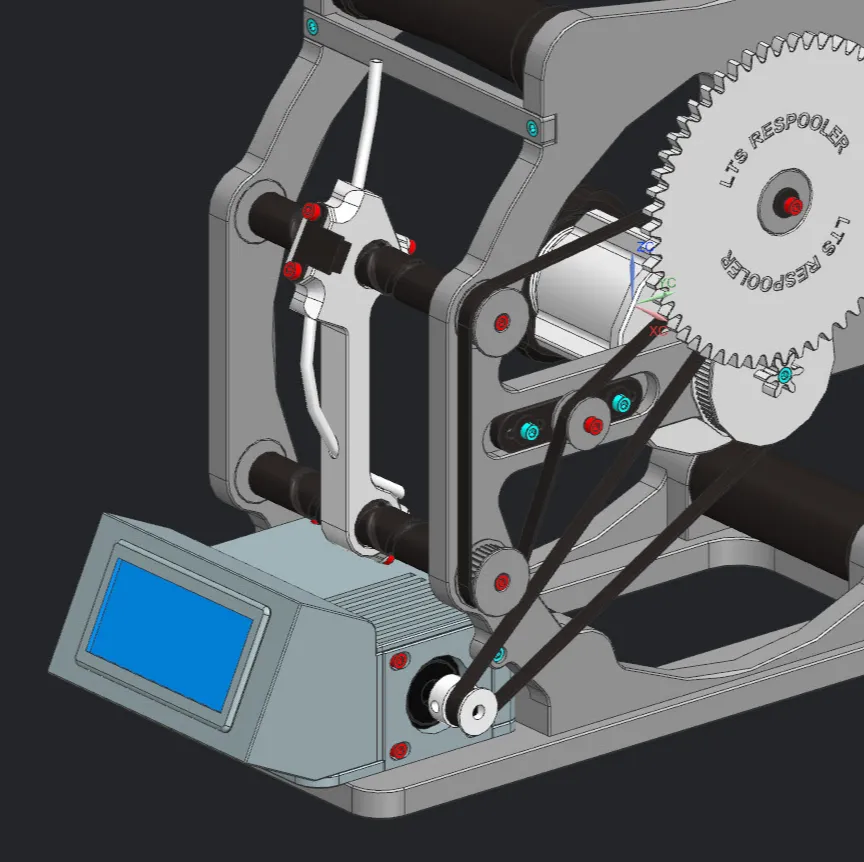
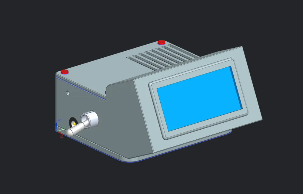
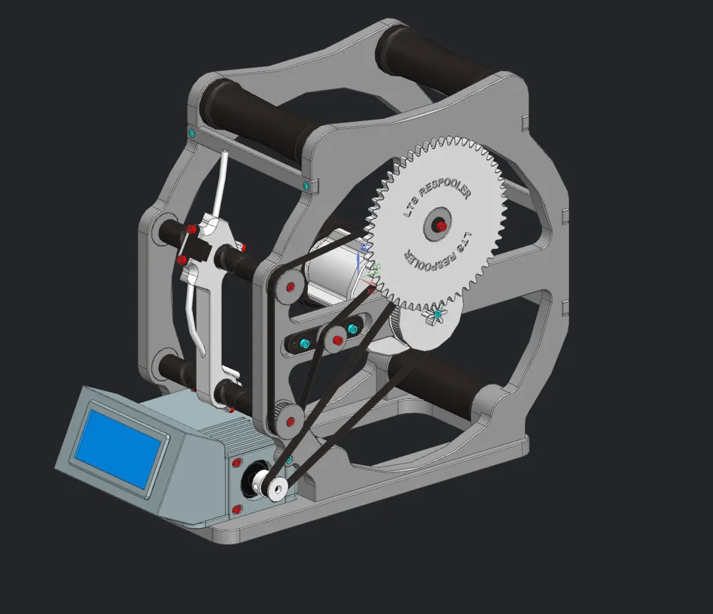
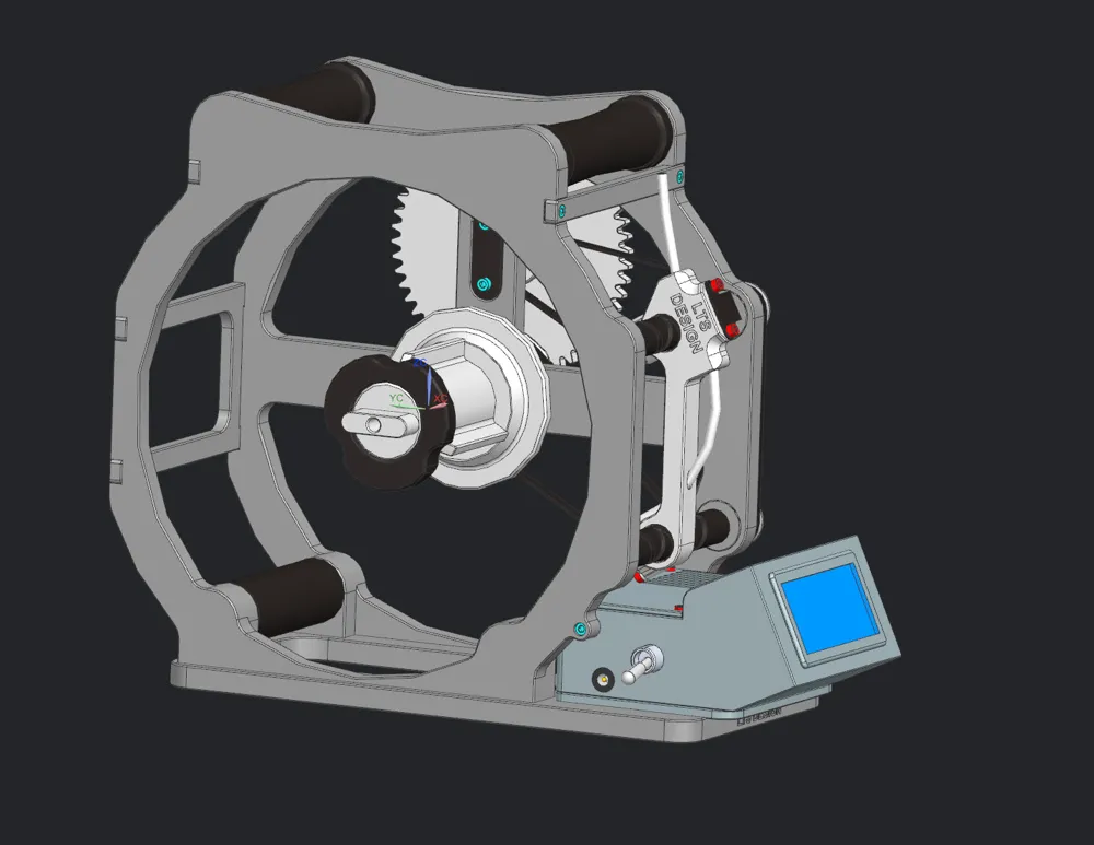
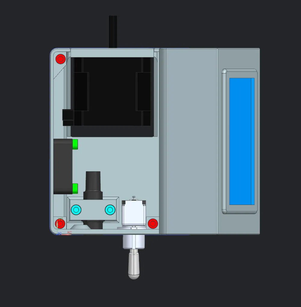
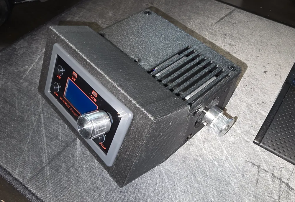
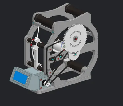
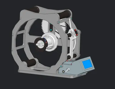
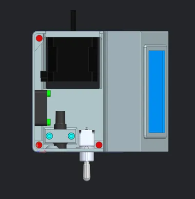
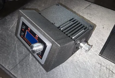
This is an alternative method to drive your stepper for the LTS respooler.
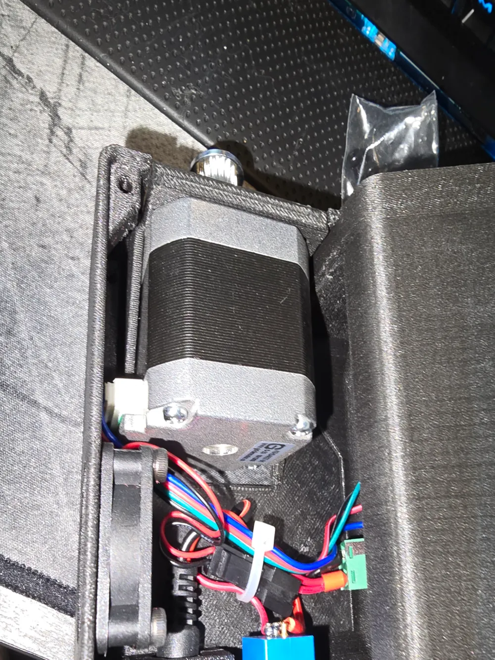
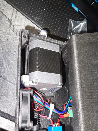
The Electronics assembly is actively cooled by a 30 x 30mm 12vdc fan.
(all electronics can be substituted with whatever you have on hand)
Required electronics:
5.5mm DC pig tail
Alternative power jack: (use alternative power jack model)
Switch: (I had used an extra aircraft switch which is not economical to use so i have provided an alternative switch for the alternative model)
Fan:
Controller:
Required hardware:
4 M3x12 for the fan
7 M3x6 for the base and lid
2 M3x10 (if using the cable clamp version)
Wiring Instructions:
Solder the positive leg from the power jack to One leg of the switch
Solder a wire to the output side of the switch
tie in the fan positive with switch output to the positive connection of the controller
tie both negative connections at the controller connection
my parameters I used for the controller:
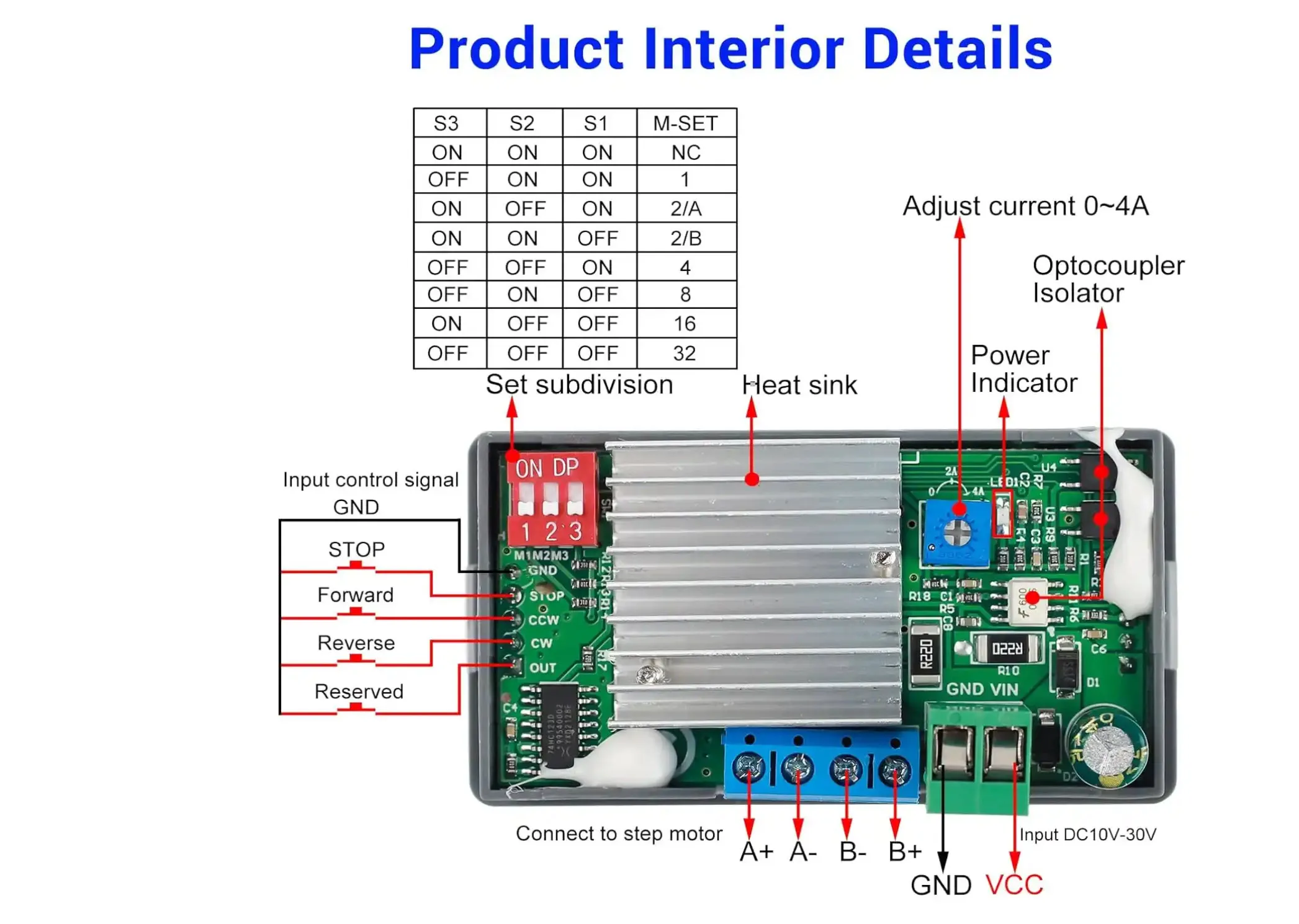
all 3 dip switches set down for 32 subdivision
F-01 : P03
F-02: 1600
F-03: 100
F-04: 1600
F-05: 999.9
F-06: 0 (- - - - )
F-07: 000.0
F-08: 000.0
F-09: 0200
F-10: 0
F-11: 0
F-12: 20
F-13: 001
For the micro switch automatic stopping you can solder the Normallly closed leads to the underside of the controller to the stop and gnd post.
This remix is based on

License



Comment & Rating (222)