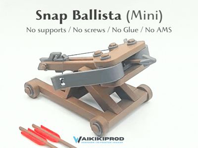
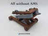
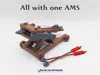
Snap Ballista (Mini)


Print Profile(4)
Bill of Materials


Description
Boost Me (for free)
Thank you so much for your boost! Your downloads and boosts allow me to keep offering my models for free. Your support means a lot to me and helps me create even more. 🙏
⚠️ Disclaimer / Warning
|
Key Features | Requirements |
|

No other hardware is required: |
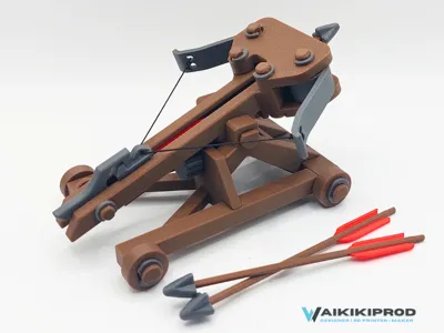
Concept and operation
One of the main goals of this project was to test and make use of material elasticity, without adding springs or external components, but relying solely on the geometry of the printed parts and their mechanical properties.

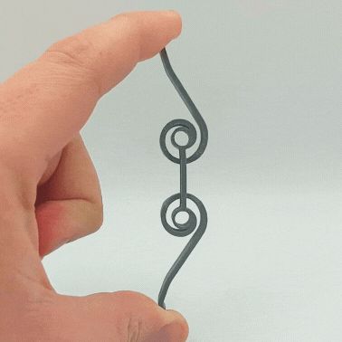
The propulsion is achieved through a PLA-printed bow with a specific geometry, designed to deform when tension is applied.
This deformation allows mechanical energy to be stored, which is then released to propel the projectile.
The elasticity of the system therefore does not come from the cord, but from the shape of the bow and the mechanical properties of PLA, directly exploited through design.
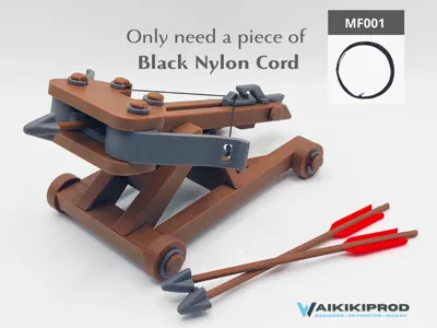
The Snap Ballista (Mini) was also designed to reuse leftover pieces of MF001 nylon cord.
The model operates with a short length of cord, around 20 cm (depending on the number of turns), making it possible to give a second life to pieces that are too short to be used in other projects.
The mechanism also includes:
- a worm screw–based elevation adjustment system, allowing precise control of the firing angle;
- a PLA-printed trigger, which also relies on the elasticity of the material to return to its initial position and lock the slider, the moving part responsible for propelling the projectile.
This project demonstrates that it is possible to achieve a functional and efficient mechanism purely through design, by playing with the shapes, thicknesses, geometry, and kinematics of printed parts.
Finally, the Snap Ballista (Mini) was designed as a simple, educational, and playful mechanical object, without screws, glue, or complex components.
It is part of a broader exploration of alternative assembly solutions, highlighting what 3D printing and snap-fit assemblies can offer when aiming to move away from traditional fasteners.
Print Settings
- Supports: Not required
- Brim: Not required
- Recommended material: PLA
- Layer height: 0.20 mm
- Wall loops: 3
- Infill: 15–20%
- Print orientation: As provided in the project files
⚠️ Important: A clean build plate is essential for successful printing. Before printing, make sure the build plate is properly cleaned and degreased to ensure optimal first-layer adhesion.
Poor bed adhesion may lead to dimensional inaccuracies, weak parts, or failed prints, especially for the snap-fit components and flexible bow.
Assembly
Projectile Launching System Assembly | |
Step 1 – Install the axle pins
|  |
Step 2 – Install the Slider and Bow
|  |
Step 3 – Install the Upper Bow Bracket
|  |
Step 4 – Secure the Bow Assembly
|  |
Step 5 – Install the TriggerInsert the Trigger into the guide rail as shown. ⚠️ Make sure the small locking tab is fully seated in the slot designed for it.
|  |
Step 6 – Secure the TriggerInsert the small trigger axle pin through the trigger and the guide rail as shown. Then install the small Snap Clip onto the axle pin to lock it in place. |  |
Step 7 – Install the BowstringThread the nylon cord through the holes at both ends of the bow and through the slider, as shown. You may use one or two strands of cord, depending on the desired draw weight. ⚠️ Nylon cord can be difficult to knot securely. Tighten each knot firmly and use multiple knots to prevent it from coming loose during use. 💡 Adjust the cord length so that the bowstring is centered and evenly tensioned on both sides.
You can now test the launch mechanism. Pull the slider back until it engages with the trigger. Then release it by pressing the trigger lever. ⚠️ Keep fingers clear of moving parts when releasing the slider. The launch mechanism may snap forward quickly. |  |
Ballista Carriage Assembly | |
Step 8 – Install the WheelsPosition the wheels on their axles as shown. Secure each wheel by installing its Snap Clip until it clicks into place. 💡 Verify that all wheels rotate freely after installation. |  |
Step 9 – Install the Elevation Adjustment ScrewInsert the Worm Screw into the elevation adjustment mechanism as shown. Secure it by installing the retaining clip on the opposite side until it snaps into place.
|  |
Carriage and Launch Mechanism Assembly | |
Step 10 – Attach the Launch Mechanism to the CarriageUse the long axle pin to attach the launch mechanism to the carriage as shown.
|  |
Step 11 – Secure the Pivot AxleInstall the small Snap Clip onto the pivot axle to lock it in place. Once secured, you can adjust the elevation of the launch mechanism by turning the worm screw. |  |
Ballista Bolt Assembly | |
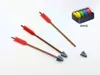
Step 12 – Assemble the BoltsInsert the bolt tips onto the bolt shafts as shown. ⚠️ The shafts are thin and flexible. To avoid bending or damaging them, hold each shaft close to its end while pushing it into the tip. Push firmly until the tip is fully seated on the shaft. |  |
Final Step – Have Fun!Your Snap Ballista is now fully assembled and ready to use. Load a bolt, pull back the slider until it locks into the trigger, aim, and fire! Have fun and enjoy your new miniature siege engine! 😊 ⚠️ Always use the ballista responsibly and never aim at people or animals.  | |
Discover my other models


License
You shall not share, sub-license, sell, rent, host, transfer, or distribute in any way the digital or 3D printed versions of this object, nor any other derivative work of this object in its digital or physical format (including - but not limited to - remixes of this object, and hosting on other digital platforms). The objects may not be used without permission in any way whatsoever in which you charge money, or collect fees.
Comment & Rating (80)