Experimental DIY Digital Level


Print Profile(1)

Description
Boost Me (for free)
Description:
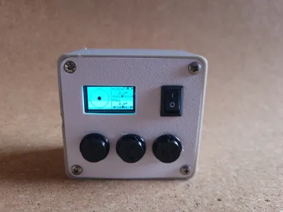
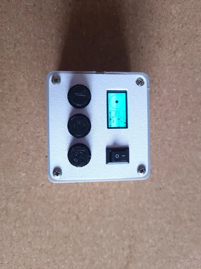
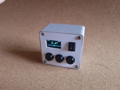
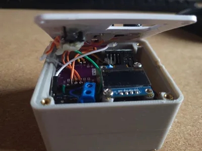
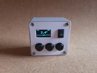
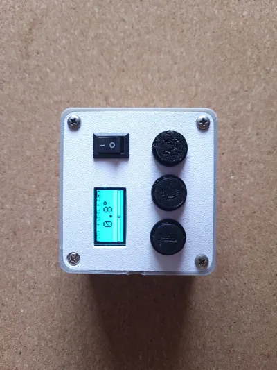
A compact, experimental DIY digital level built around an ESP32-C3, MPU-6050, and a 0.96" OLED display. It provides real-time pitch and roll measurements with a clean bubble-style interface, multiple display modes, and adjustable tolerance. The device includes onboard calibration, battery monitoring, and a simple 3-button interface, all designed to fit into a small 3D-printed enclosure.
This project is intended for makers who want a customizable, portable digital level and a fun electronics build.
Features:
- Real-time bubble level for instant alignment feedback
- Multiple display modes (bubble, large pitch, large roll, single axis)
- Screen color inversion when within tolerance for clear visual feedback
- Smooth and stable readings using Kalman filtering and averaging
- Zero button for calibration on any surface
- Adjustable tolerance (±0.5° to ±5°)
- Freeze/hold function to lock readings
- Battery voltage indicator
- Auto sleep after 30 seconds of inactivity
- Splash screen with button reference
- Left Button: Tolerance, Middle Button: Calibrate, Left Button: Modes
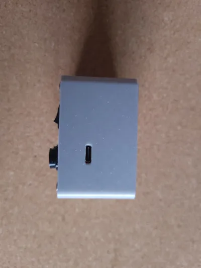
- The USB-C port is only for uploading code and serial communication. It is not for charging the batteries.
Parts List:
Microcontroller: Lolin ESP32-C3 Mini
IMU: GY-521 MPU-6050 (6-axis) ()
Display: 0.96" OLED SSD1306, 128×64, I2C ()
Voltage sensor: DC 0–25V voltage sensor module
3x Tactile buttons: 6×6mm 4-pin tactile push buttons
Simple On-Off Switch
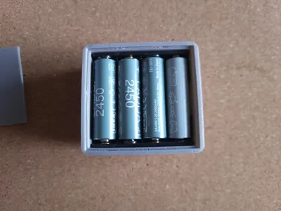
4 Slot AA Battery pack: I used four 1.2V rechargeable batteries from Ikea → If you want to build this, make sure that your batteries don't exceed 5V in total
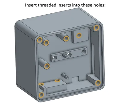
M3 screws and threaded inserts
Links suggestions (from Aliexpress):
Tips:
- Use hot glue to secure components
- Print button caps in TPU
- Use "The Perfect TPU Profile" by AllFor3D for best button cap results
Pin Reference:
| Signal | GPIO Pin |
| I2C SDA (IMU + OLED shared) | GPIO 8 |
| I2C SCL (IMU + OLED shared) | GPIO 10 |
| Voltage sensor signal (S) | GPIO 1 |
| Button — MODE | GPIO 4 |
| Button — CAL | GPIO 3 |
| Button — TOL | GPIO 2 |
| All VCC (IMU, OLED) | 3.3V |
| All GND | GND |
| Battery + | VBUS |
Wiring Diagram:
ESP32-C3 Mini
┌─────────────────────────────┐
│ 3V3 ────────────────────────┼──► IMU VCC
│ └─────────────────────┼──► OLED VDD
│ │
│ GND ────────────────────────┼──► IMU GND
│ ├─────────────────────┼──► OLED GND
│ ├─────────────────────┼──► BTN other legs
│ └─────────────────────┼──► Voltage sensor V-
│ │
│ GPIO 8 (SDA) ───────────────────┼──► IMU SDA
│ └──────────────────┼──► OLED SDA
│ │
│ GPIO 10 (SCL) ─────────────────┼──► IMU SCL
│ └───────────────────┼──► OLED SCK
│ │
│ GPIO 1 ───────────────────────┼──► Voltage sensor S
│ GPIO 4 ───────────────────────┼──► MODE button
│ GPIO 3 ───────────────────────┼──► CAL button
│ GPIO 2 ───────────────────────┼──► TOL button
│ │
│ VBUS ─────────────────────── ┼──► Battery +
└─────────────────────────────┘
IMU (GY-521) OLED (SSD1306)
┌─────────┐ ┌─────────┐
│ VCC──3V3 │ │ VDD─3V3 │
│ GND──GND │ │ GND──GND │
│ SCL──G10 │ │ SCK──G10 │
│ SDA──G8 │ │ SDA──G8 │
│ XDA──NC │ └─────────┘
│ XCL──NC │
│ ADO──NC │
│ INT──NC │
└────────┘
NC = Not connected
G = GPIO
Voltage Sensor Module Battery
┌──────────────┐ ┌────────┐
│ V+ (screw) ──────┼─────┼─── BAT+ │
│ V- (screw) ──────┼─ GND ┼─── BAT- │
│ S ──── G1 ─────│ └────────┘
└──────────────┘
Buttons (all identical wiring)
GPIO 4 ──┤MODE├── GND
GPIO 3 ──┤CAL ├── GND
GPIO 2 ──┤TOL ├── GND
Use opposite legs of the 4-pin button
(left leg → GPIO, right leg → GND) → i recommend to wire the GNDs of the Buttons in series to save space
ON-OFF Switch
Connect Switch to the Battery's positive pole and the ESP32 VBUS/Voltage Sensor + Screw Terminal
Code (On GitHub):
https://github.com/ruidan-web/esp32-digital-level/tree/main
Project Status:
This is an experimental DIY project. Accuracy may vary depending on calibration, assembly, and component quality
Disclaimer:
This project is provided for educational and experimental DIY purposes only. The design, documentation, wiring diagrams, and software are provided as-is, without any guarantees of accuracy, completeness, or safety.
By building or using this project, you agree that you do so at your own risk. I am not responsible for any damage, injury, malfunction, data loss, incorrect measurements, or other issues that may occur from the use, assembly, or modification of this project.
License
You may create derivative works based on this object, provided that all such derivative works are published exclusively on the MakerWorld platform and include proper attribution to the original creator. You may not share, upload, host, distribute, or publish this object—or any derivative work of this object—on any other digital platform, marketplace, or distribution channel. Commercial use of this object and any derivative works is strictly prohibited. This includes, but is not limited to, selling, renting, sublicensing, or using the object in any context in which you receive monetary compensation or other financial benefits.
Comment & Rating (4)