Search models, users, collections, and posts
Case 5V Power Supply (20A / 40A / 50A)
IP Report


Print Profile(6)

Case for 5V / 20A Power Supply, Rubber Feet
Designer
8.1 h
4 plates

Housing for 5V / 40A Power Supply, Rubber Feet
Designer
9.4 h
4 plates

Case for power supply 5V / 40A, wall-mounted
Designer
9.1 h
3 plates

Case for 5V / 50A Power Supply, Rubber Feet
Designer
8.6 h
4 plates
Click to see more
Open in Bambu Studio
Boost
29
68
6
3
65
29
Released
Description
Content has been automatically translated.
German | English |
|
|
English
- For a current matrix project with over 2000 LEDs (8 mm, wired), I needed approx. 125A at 5V for maximum illumination. I opted for 4 power supplies, each with 40 A. The matrix is powered row by row.
- The power supplies are modular and do not have a conventional housing, as they are intended for installation in a larger unit.
- To avoid having excessively long cables to the matrix rows (the matrix is approx. 2.5m x 3.0m in size), the four power supplies should be installed to the left and right of it.
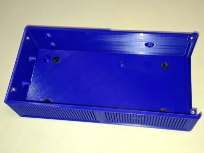
- This required sturdy housings that could be mounted on the wall.
- The housings should also be used in a modified form for experiments and other (smaller) projects.
- The ventilation of the power supplies in the housing is based on the location of the ventilation openings in the power supplies. In addition, a 3 mm gap is maintained in all directions from the walls, the bottom and the cover.
- There are several variants of the housing:
- For 5V / 20A
- Power supply dimensions: 200mm x 97.6mm x 38mm
- With holes for attaching rubber feet (as 3mf file)
- Without holes in the base; if feet are required, they can be glued on
- For 5V / 40A
- Power supply dimensions: 200mm x 109.7mm x 50mm
- With holes for attaching rubber feet (as 3mf file)
- Without holes in the base; if feet are required, these can be glued on
- With wall mounting (without holes in the base) (as 3mf file)
- For 5V / 50A
- Power supply dimensions: 215mm x 114,5mm x 50mm
- With holes for attaching rubber feet (as 3mf file)
- Without holes in the base; if feet are required, these can be glued on
- With wall mounting (without holes in the base) (as 3mf file)
- The dimensions are maximum values. In terms of length, I also had a device that was 5mm shorter, with the same mounting points.
- For 5V / 20A
- The front panel can be customized for the respective purpose.
I have added a blank front panel for customization for all sizes to the parts list (as stl and step files).
Assembly
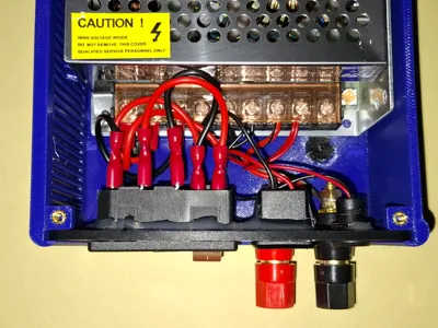
- Before the finished printed housing can be used, the 4 threaded bushings must be installed.
- Installing the front panel may pose a challenge for some, but I have included a few photos as inspiration. The use of solder or plug connectors is up to the individual.
- 3D printing
- The material I used is Bambu PETG HF.
- For the cover, it is important to note that the many fine ventilation slots require very good bed adhesion. The textured PEI plate does not meet this requirement. The Smooth or Super-Tack plate is better.
- For the front plate, you can add lettering in the slicer according to your personal taste.
The layer height can be 0.2 mm or 0.28 mm to accelerate printing.
- Materials
- M3 threaded bushings: 4 pieces
- 20A*40A: M3x10mm screws: 11 pieces (4 for the cover and 7 for the power supply)
- 50A: M4x12mm screws: 8 pieces for the power supply, M3x10mm or M3x8mm for the cover
- The material for the front panel depends on your personal requirements.
- The parts used in this project are:
- Power supply 5V 20A or 40A, e.g., S-200-5 or 50A, e.g. S-350-5 (see photos)
- IEC connector with power switch and fuse 1x
(don't forget to order fuses) - USB-A socket 1x
- USB-C socket 1x
- Laboratory sockets for banana plugs 2x (red and black)
- Mini Digital Voltmeter
- Notes on the power supply unit
- There are many options available. The designs appear to be more or less very similar. The devices I used all had the mounting screws in the same place, but differed in length and weight (all devices have fundamentally different mounting points).
- Tip: Before printing the entire housing, you may want to create smaller partial prints to check the mounting positions.
License
This user content is licensed under a Standard Digital File License.
You shall not share, sub-license, sell, rent, host, transfer, or distribute in any way the digital or 3D printed versions of this object, nor any other derivative work of this object in its digital or physical format (including - but not limited to - remixes of this object, and hosting on other digital platforms). The objects may not be used without permission in any way whatsoever in which you charge money, or collect fees.
Comment & Rating (6)