
Latch Y Splitter - No-Bend Switching
Print Profile(2)


Bill of Materials


- PC4-M10 Pneumatic Connecter for PTFE Tube x 3:
Description
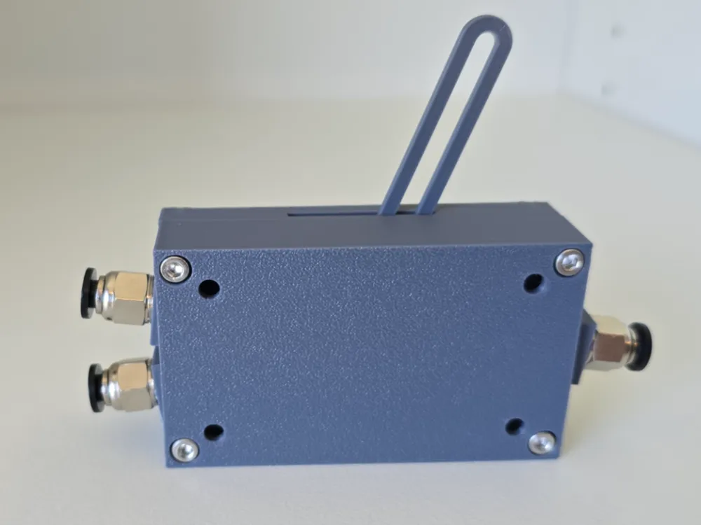
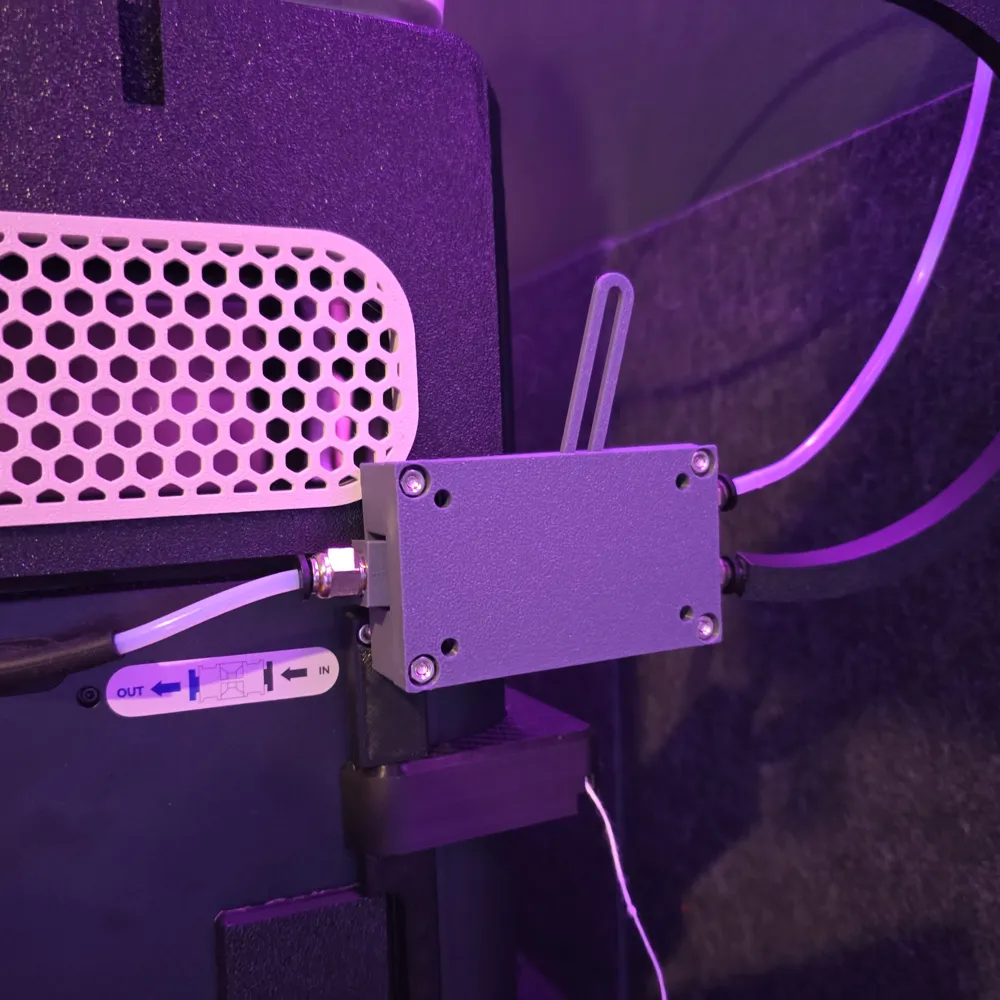
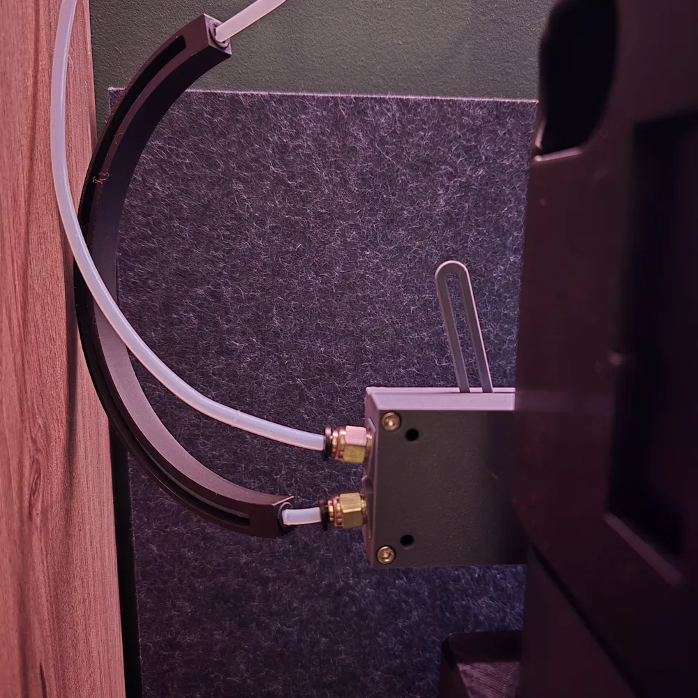
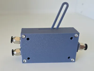
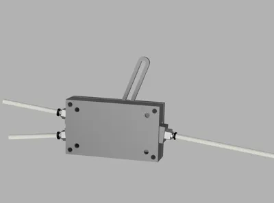
Latch Y-Splitter – Reliable, No-Bend Switching
UPDATE:
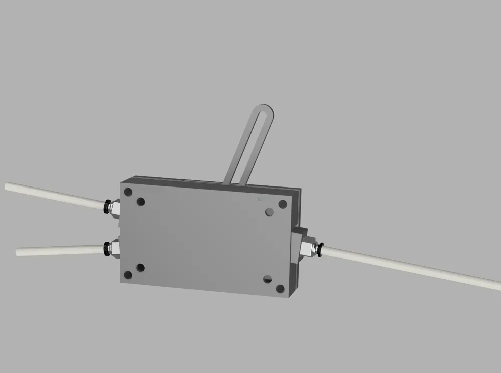
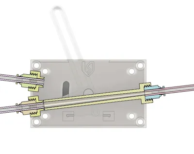
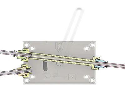
On request, I have made an alternate sliding slot with a reverse taper, this allows the Latch Splitter to work as either:
- Two Inputs : One Output, OR
- One Input : Two Outputs (NEW!)
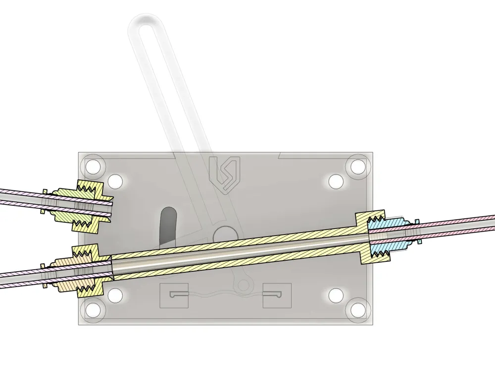
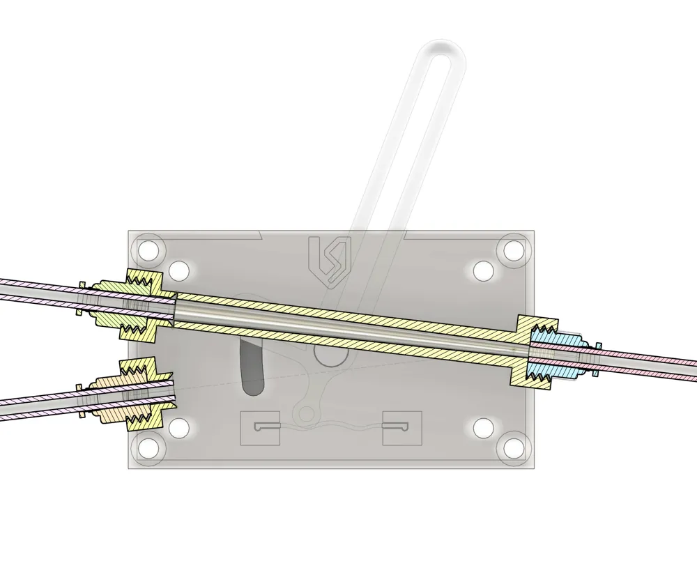
I designed this Latch Y-Splitter because I found that many other splitter models rely on bending internal parts to divert filament. While clever, that approach can often cause issues—differences in print settings, filament variations, or even small imperfections in the print can lead to blockages and jams.
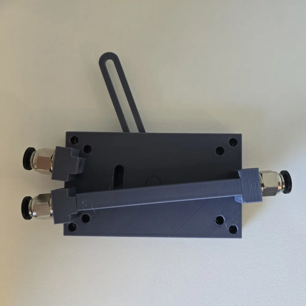
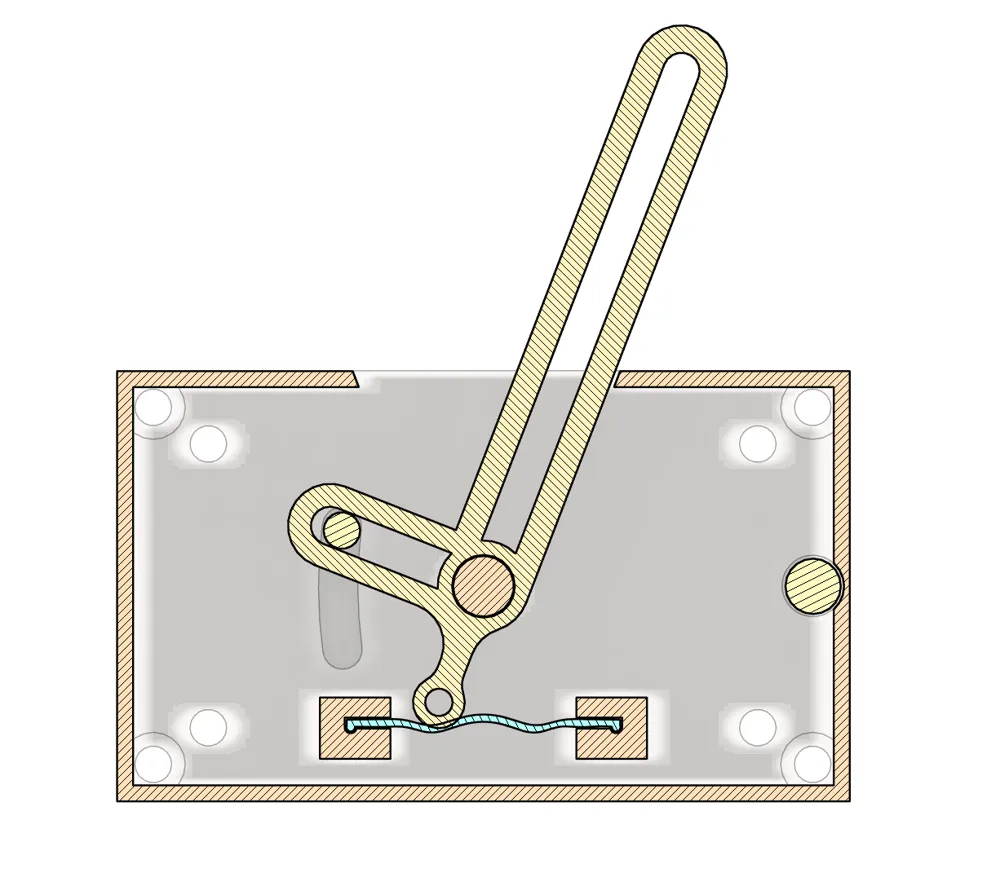
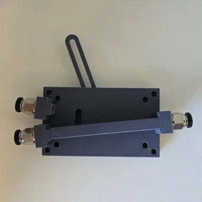
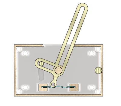
My solution was to move away from the bending (curved) method and instead use a mechanical latch with a tapered internal bore. This provides a clean, consistent path for the filament and minimizes the risk of snags or failures. The latch gives a firm, positive engagement that’s both simple to use and reliable over time.
Key Features
✅ Mechanical Latch System – Provides dependable switching without curved internal parts.
✅ Tapered Internal Bore – Guides filament smoothly and reduces drag.
✅ Durable & Secure – Printed with robustness in mind, paired with fittings that stay in place.
✅ Ease of Use – The latch handle makes switching fast and intuitive.
✅ Reduced Blockages – Linear internal structure designed to work more consistently across different print and filament conditions.
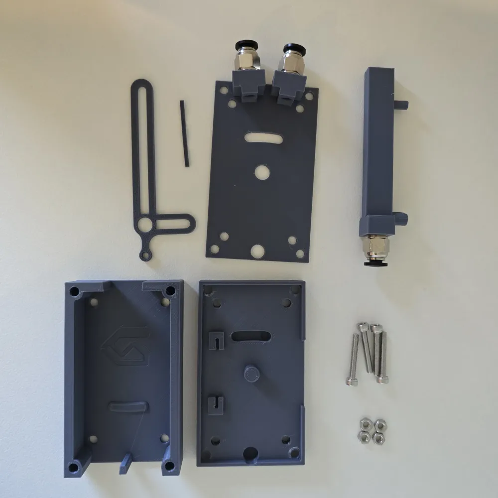
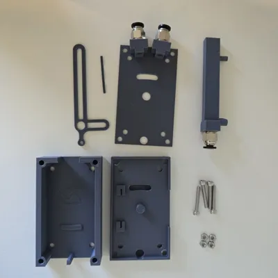
Parts List
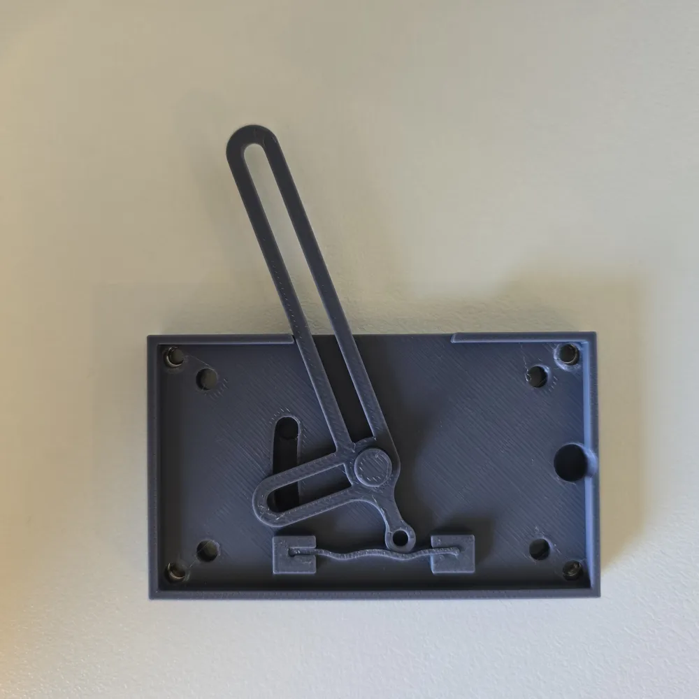
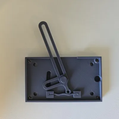
- Back Cover
- Body
- Top Cover
- Switch
- Flex Latch
Sliding Slot
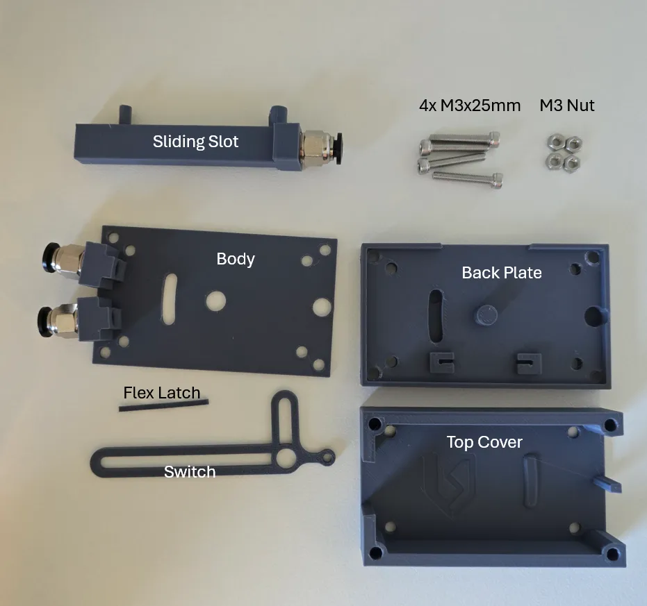
Assembly Instructions
Insert Switch & Flex Latch: Place the switch and flex latch into the back plate.
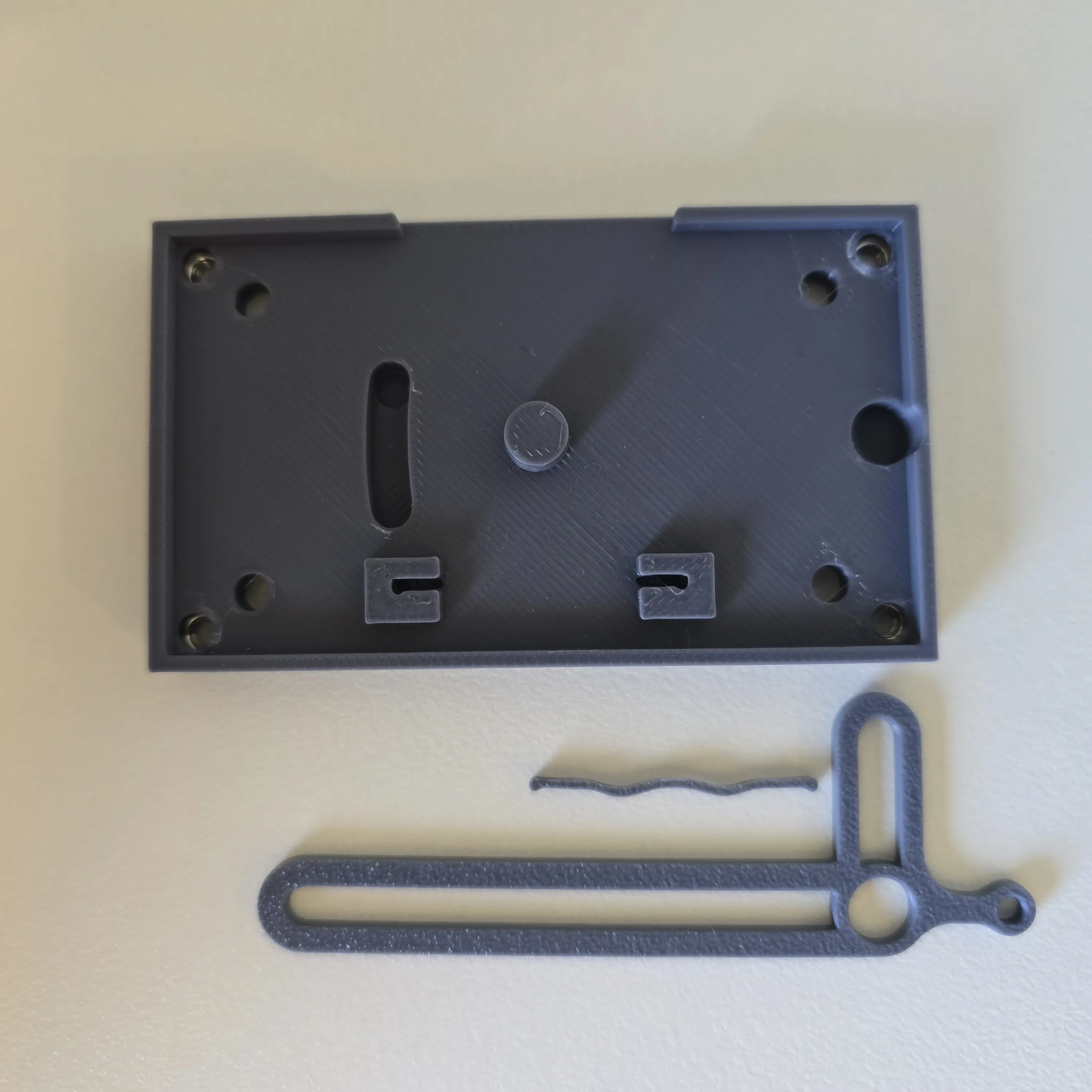
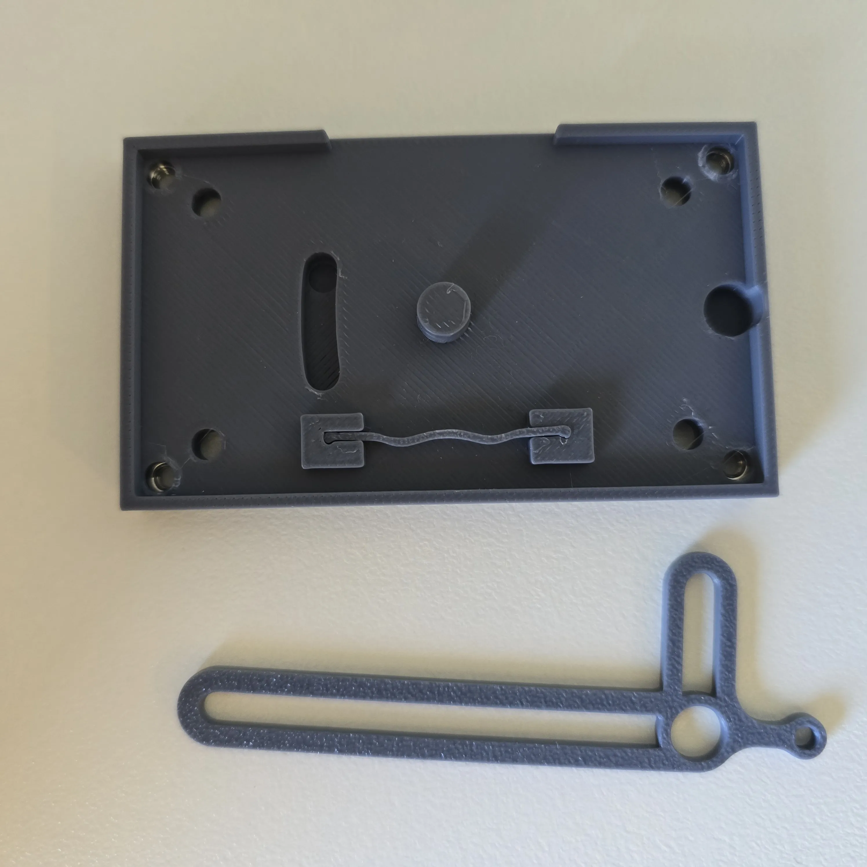
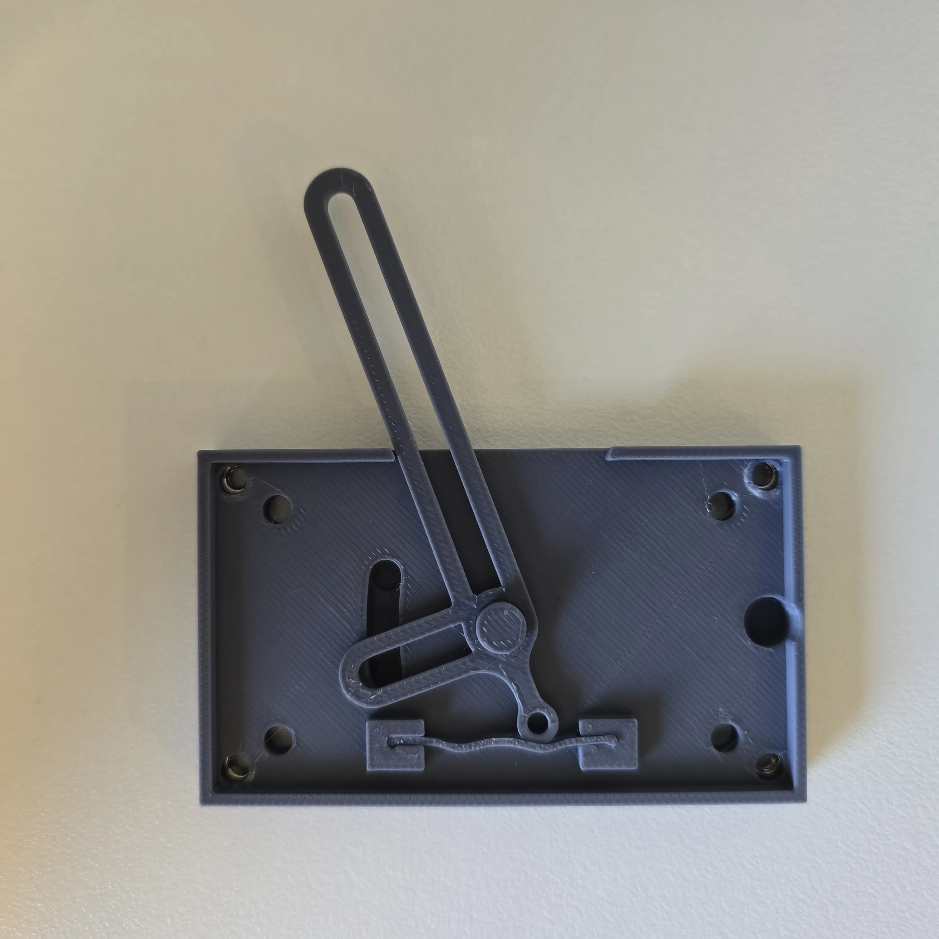
Align the Body: Position the centre body over the latch mechanism using the centre latch axle and slot holes for alignment.
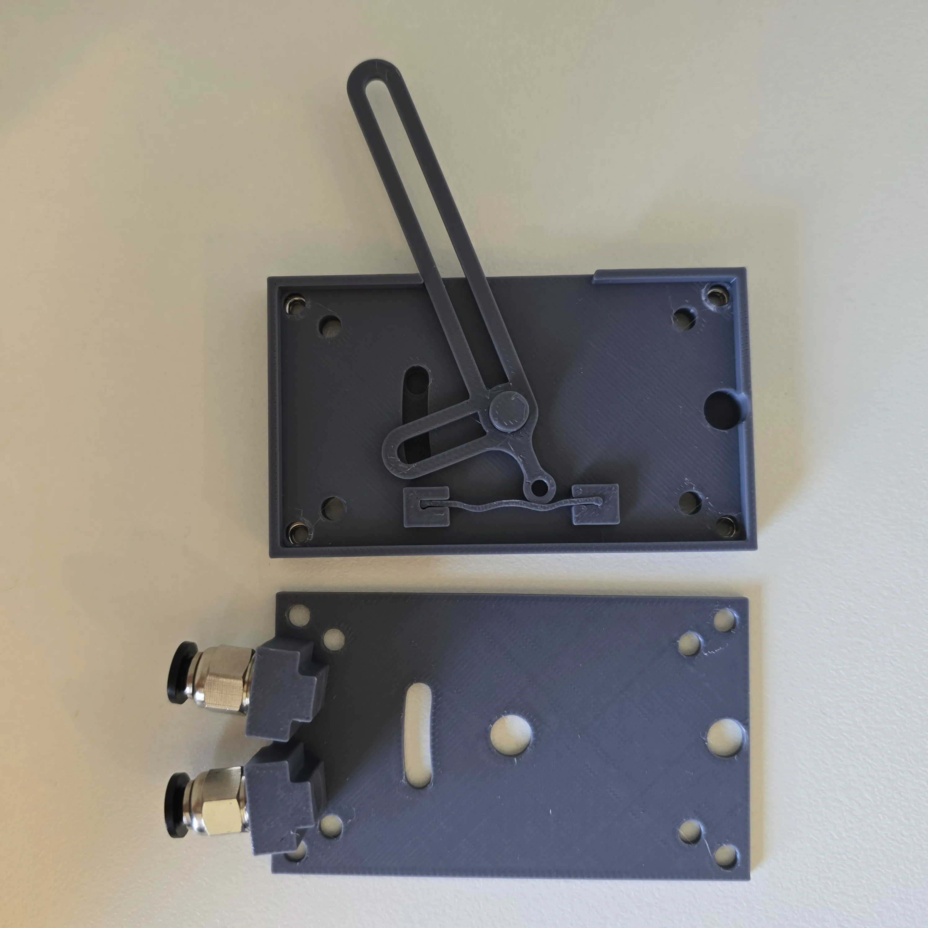
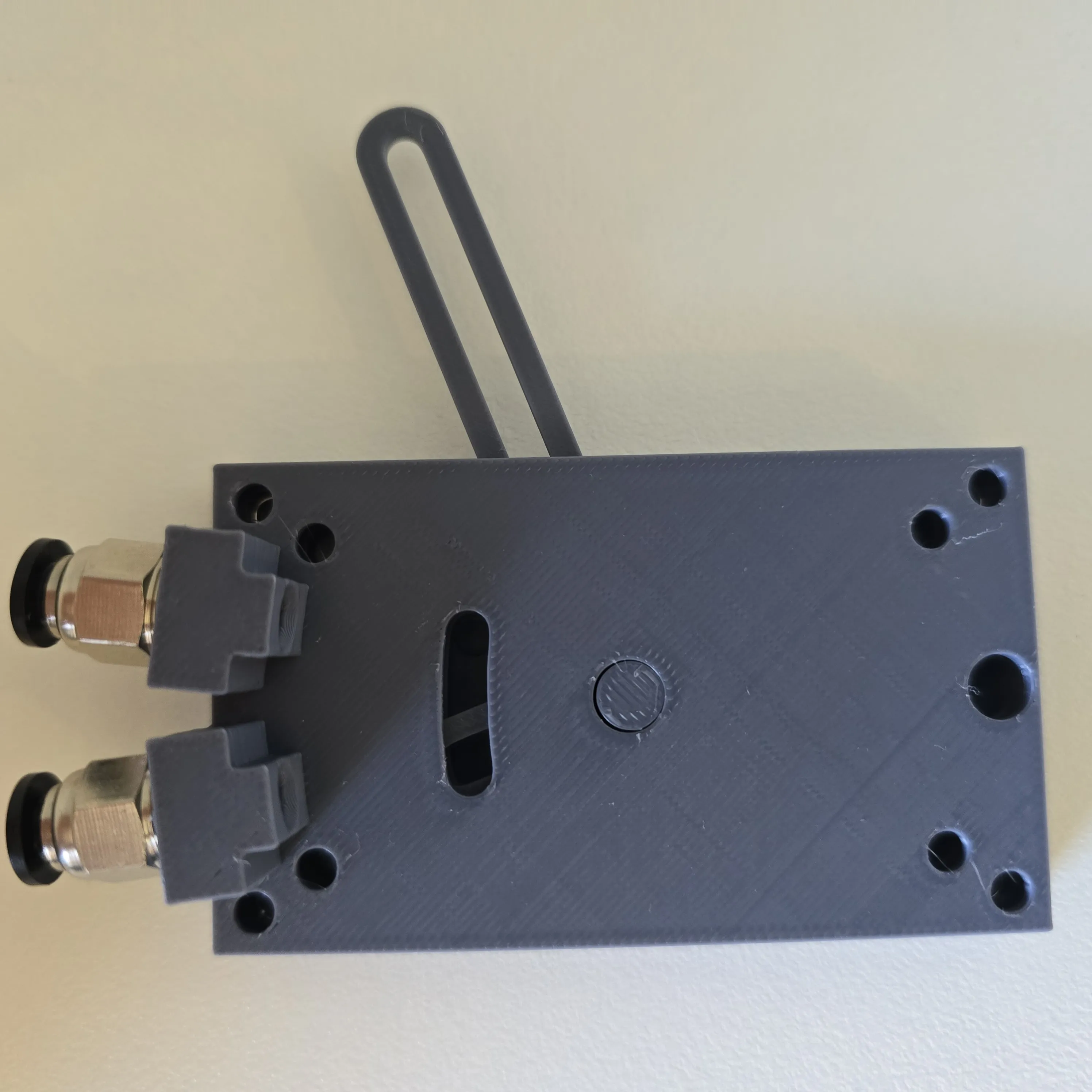
Install the Slot: Insert the slot, ensuring the pin engages correctly with the switch mechanism.
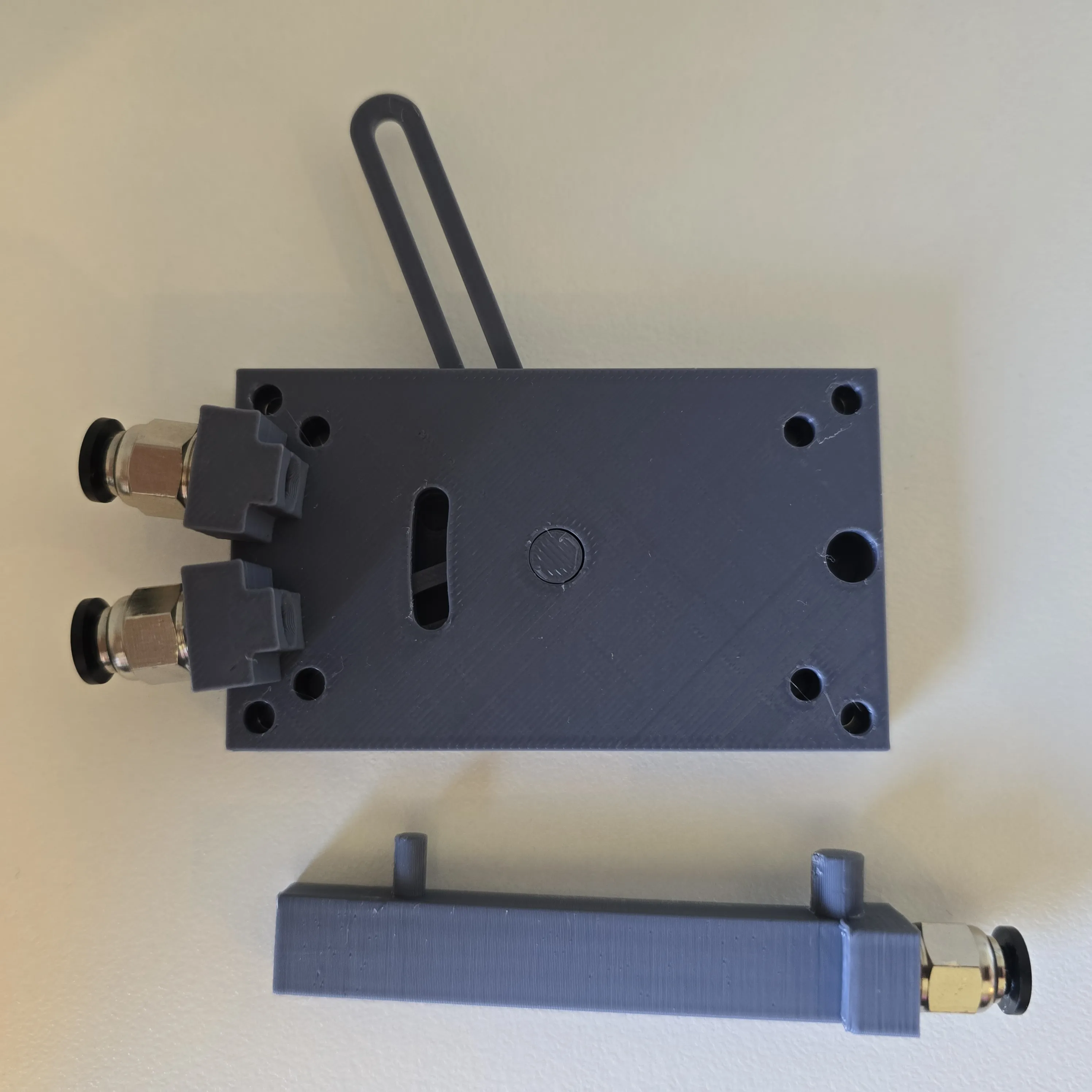
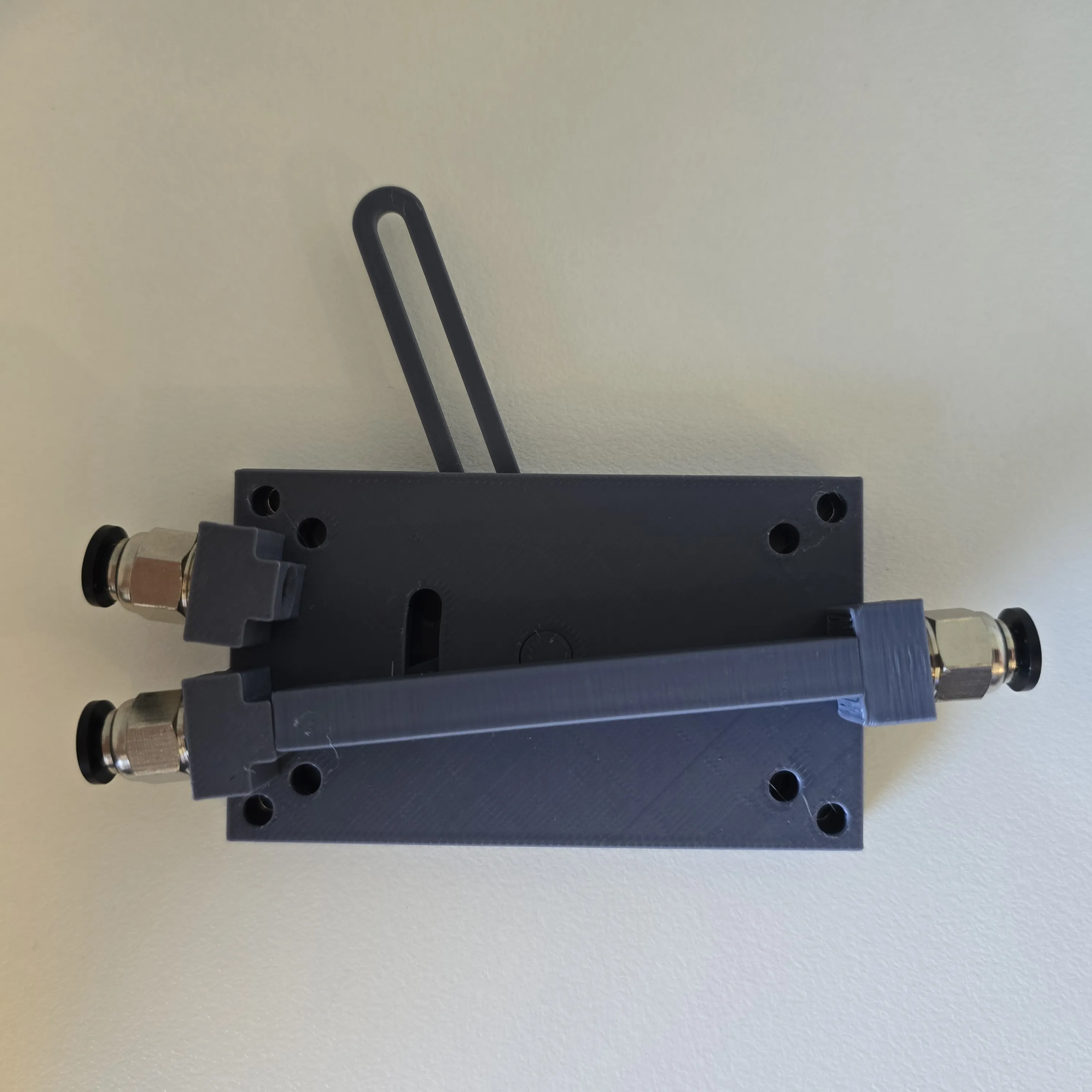
- Use a small knife or file to remove any support material from the slot pins for smooth motion.
Test the Mechanism: Before proceeding, confirm smooth motion and work the switch several times to ensure proper operation.
- Attach the Top Cover: Place the top cover on and secure it with the four corner screws.
⚠️ Do not overtighten, as this may crack the rear plate or create excessive friction on the slot.
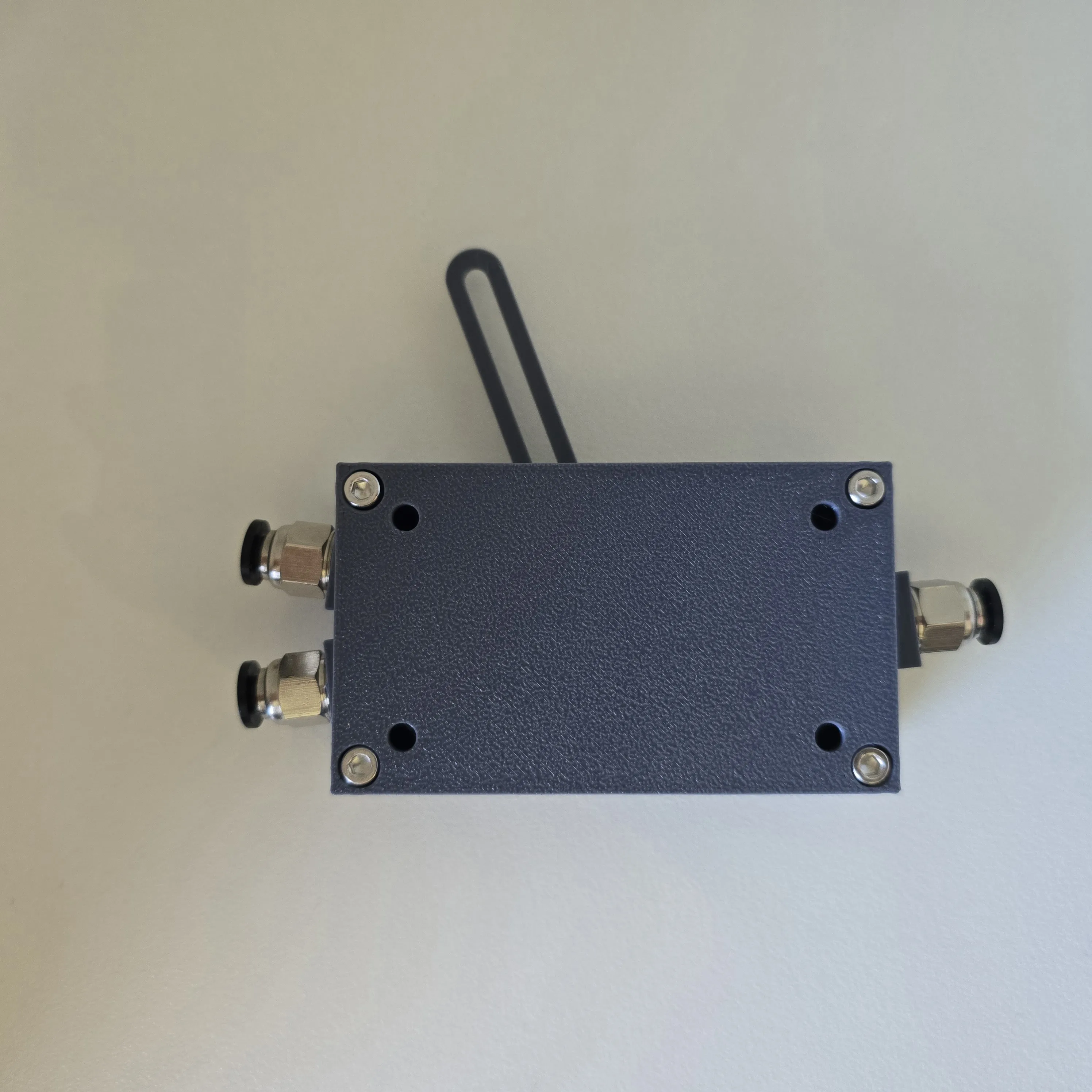
Installation Options
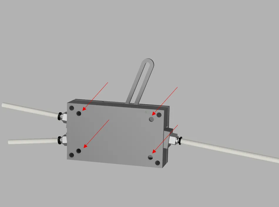
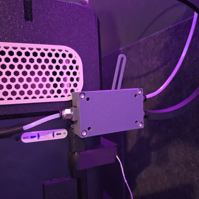
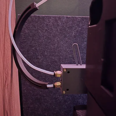
- Option 1: Secure using double-sided tape.
Option 2: Use an M3×30mm screw and one of the four mounting holes to attach the splitter to the P1/X1 frame.
License

You shall not share, sub-license, sell, rent, host, transfer, or distribute in any way the digital or 3D printed versions of this object, nor any other derivative work of this object in its digital or physical format (including - but not limited to - remixes of this object, and hosting on other digital platforms). The objects may not be used without permission in any way whatsoever in which you charge money, or collect fees.


Comment & Rating (15)