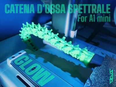
SPECTRAL BONE CHAIN (For A1 mini)


Print Profile(1)


Description
SPECTRAL BONE CHAIN (PRINT BED CABLE PROTECTOR FOR A1 MINI)
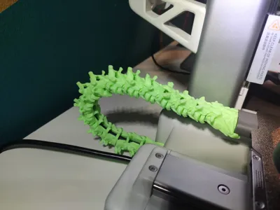
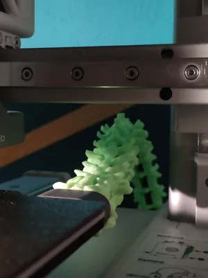
I created this cable protector chain to customize my small A1 mini and give it a more original and unique look, without neglecting the object's functionality as it also serves as a cable protector!!!
I decided to share my work with you, which my 'Miní' seems to absolutely love too!!!!
Boost Me (for free)
If you appreciate my models and would like to support my work, boosting is the free way to do it!!! Thank you!!!! 😉
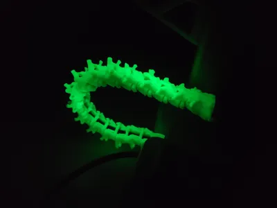
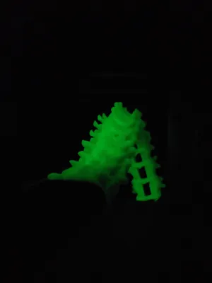
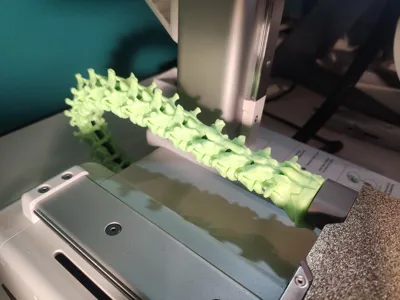
🟢For this project, I used BambuLab's “Glow - Green” filament, which proved essential for giving this bone chain the spectral touch I wanted.
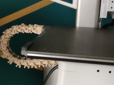
⚪I also printed it with a “BONE” filament from eSun.
Subsequently treated with acrylic to give it a more realistic coloration.
I created:
🔹10 UNIQUE vertebrae
🔹7 IDENTICAL central vertebrae
🔹 15 IDENTICAL closures that will close the belly of the chain to secure the cable inside.
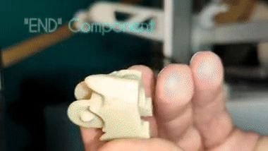
TO SIMPLIFY PRINTING AND FACILITATE SUBSEQUENT ASSEMBLY, I HAVE DIVIDED THE CHAIN INTO 4 PLATES:
START - CENTRE - END - CLOSURES
Below, I will illustrate the correct assembly of the vertebrae.
This chain was designed considering the problem of some chains rubbing against the cooling fan located under the hotend. Obviously, if assembled correctly, this problem will not occur, so I invite you to follow the guide for correct assembly.


WHAT DO YOU THINK? CURIOUS TO READ YOUR COMMENTS, HAPPY PRINTING!!!!! 🫡
License
You shall not share, sub-license, sell, rent, host, transfer, or distribute in any way the digital or 3D printed versions of this object, nor any other derivative work of this object in its digital or physical format (including - but not limited to - remixes of this object, and hosting on other digital platforms). The objects may not be used without permission in any way whatsoever in which you charge money, or collect fees.
Comment & Rating (47)