Easier Electronic for LTS Respooler using USB PD


Print Profile(3)


Bill of Materials


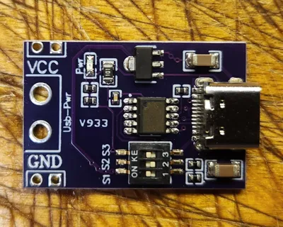
- USB-C PD Trigger Board x 1: https://www.amazon.com/dp/B0CGVD7B83
- SMC02 Stepper Motor Driver and Controller x 1: https://www.amazon.com/Stepper-Controller-Reverse-Programmable-Communication/dp/B0DN62G5BB
- 3010 12V DC Brushless Cooling Fan x 1: https://www.amazon.com/Antrader-Brushless-30x30x10mm-Extruder-Humidifier/dp/B07K1ZLLH7/
- JST RCY-2 Male & Female Connectors with Cable x 1: https://www.amazon.com/Silicone-Connector-SIM-NAT-Connectors/dp/B071XN7C43
- JST XH-2 (2.54mm) Female Connector with Cable x 1: https://www.amazon.com/OliYin-10pairs-Balance-Connector-Silicone/dp/B09KH68WVL
Description
Attention: LTS's new “Pro” version utilizes a servo motor to move the filament guide instead of the worm gear making this control option no longer compatible with the new version. This control option is still compatible with the original version.
I needed a respooler to respool a spool of filament. Sounds like a job for the awesome LTS Original Respooler.
While looking at the LTS control board website, I noticed there was no inventory available. Another quick search, I found the “Easy Electronics alterative for LTS Respooler” that uses a commercially available SMC02 stepper controller (https://www.aliexpress.us/item/3256803378995316.html or https://www.amazon.com/Stepper-Controller-Reverse-Programmable-Communication/dp/B0DN62G5BB).
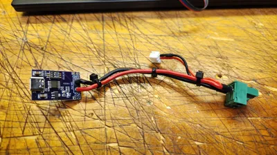
Rather than using a barrel plug and a 12V PSU, I decided to use a USB PD (Power Delivery) trigger board (https://www.aliexpress.us/item/3256806814572056.html or https://www.amazon.com/dp/B0CGVD7B83) I had laying around. I spliced in a JST XH-2 (2.54mm) female connector to power the 3010 12V fan (https://www.aliexpress.us/item/3256801117079696.html or https://www.amazon.com/Antrader-Brushless-30x30x10mm-Extruder-Humidifier/dp/B07K1ZLLH7).
To auto-stop the respooler, I soldered in a JST RCY-2 Male connector to the “Stop” and “Ground” pin on the back of the SMC02.
I than soldered in the JST RCY-2 Female connector to the “black” and “white” cables on the limit switch. I removed the unused “red” cable for a future project. The hole on the cover has been resized to fit the JST RCY connector. See the “Edit Nov 3, 2025” note below for more information.

NOTE: The above schematic should be used for reference only. Verify wiring for your controller, stepper motor, and additional components before energizing since wiring could vary by manufacturer.
NOTE: The limit switch shown in the above schematic is the limit switch style used with the LTS Respooler v3 and older. LTS has updated the switch used to a one available on MakerWorld. I have ordered this new switch to test and update these instructions when I have time.
I set my trigger board to 12V. After plugging in an USB-C cable connected to high quality 35W PD plug, my LTS Respooler came to life.
If you need more information on USB PD, see this link: https://www.usb.org/usb-charger-pd
For more information, see IvIast3r's original design found here: https://makerworld.com/en/models/553484-easy-electronics-alternative-for-lts-respooler#profileId-913644
As mentioned by Ivlastsr, I have used the following settings SMC02 stepper controller:
The 3 dip switches set down for 32 subdivision
F-01: P03
F-02: 1600
F-03: 950
F-04: 1600
F-05: 750
F-06: 0001
F-07: 000.0
F-08: 000.0
F-09: 0200
F-10: 0
F-11: 0
F-12: 20
F-13: 001
Additional parts I used:
JST RCY-2 Male & Female Connectors: https://www.aliexpress.us/item/3256806807985387.html or https://www.amazon.com/Silicone-Connector-SIM-NAT-Connectors/dp/B071XN7C43
JST XH-2 (2.54mm) Female Connector: https://www.aliexpress.us/item/3256806041022852.html or https://www.amazon.com/OliYin-10pairs-Balance-Connector-Silicone/dp/B09KH68WVL
You might want to look at my updated spool retainer nut to solve several issues I have with the designer's original design. See this link for my updated version: https://makerworld.com/en/models/1343890-extended-retainer-nut-with-hex-for-lts-respooler
Edit Oct 19, 2025: I added some additional pictures to show how I wired things up. I've also added more links to the parts I used. Hopefully it helps.
Edit Nov 3, 2025: While creating the basic wiring schematic, I realized that I soldered my limit switch to the wrong pins and was actually shorting things out. After making the correction, my limit switch stopped working. As noted by a comments of the original control, using the original limit switch as specified has issues. I soldered in a jumper to the common pins and broke off the SMD compactors and resistors and everything started to work again, See the last picture for more information.
Edit May 29, 2026: Reviewing the recent comments, I've added a note that the schematic is for refence use and a high quality USB-C PD power supply should be used.
Boost Me (for free)
Please help me fund future projects by giving me a boost.

Comment & Rating (47)