Modular Edge System: Interlocking Tool Organizer


Print Profile(8)


Description
Description
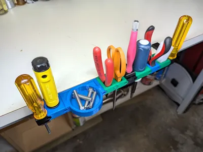
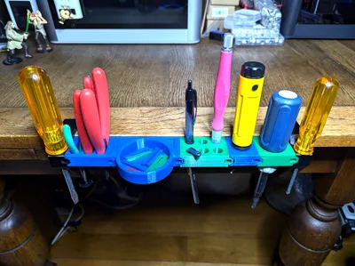
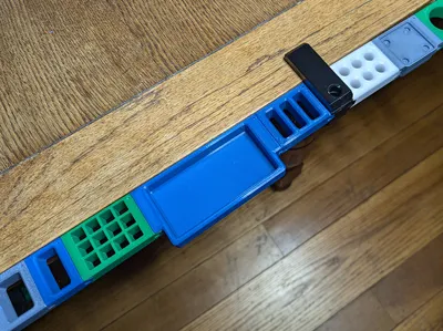
The Modular Edge System (MES) is an edge-mounted tool organizer that allows for quick access to your most-used tools. With a variety of modules, you can easily customize your setup to fit your needs. MES will fit against most flat surfaces between 85 and 5 millimeters thick and at least 30 millimeters deep.
Introduction
I wanted easy access to my tools without them cluttering my workspace. Wall organizers or mounting them next to my 3D printers wasn't ideal. Storing them in a toolbox or drawer risked forgetting their location. I needed a customizable solution for my workflow, tools, and parts, one that could be easily adapted. Unable to find a perfect fit, I created the Modular Edge System (MES) - interlocking tool and parts holders. I've created a few modules featuring rectangular, round, square, and hexagonal holes, along with various sized parts bins.
I've also uploaded a Fusion 360 source file so that you can create your own tool holder modules.
I printed the modules and clamps using PETG but any filament should work. No supports are needed. Make sure that your filament is dry as I had issues with a module that printed using wet filament not fitting correctly.
Design Criteria
The following are design goals that I tried to achieve for this project.
- Easy to assemble and disassemble
- Be customizable
- Be able to hold a wide range of tools
- Allow for infinite length of interlocking modules
- Print with no supports
Updates
12/21/2025
- Added a screw with a cap to better stabilize the clamps. Cap easily snaps on and off of the new screw. It also swivels a little.
11/17/2024
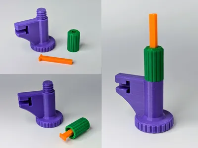
The tip on the Locking Pin Removal Tool broke on me so I decided to redesign it with a stronger tip. The tip is also replaceable so that if it does break you don't have to reprint the whole tool. I also made it smaller and more ergonomic.
To assemble the new Locking Pin Removal Tool, insert the tip into the cap through the square hole then screw the cap onto the handle.
10/05/2024
- Added the missing module mount piece to the 85mm Mid Mount Clamp plates in the "Modular Edge System - Clamps.3mf" file.
9/24/2024
- Added 85mmx30mm and 85x44mm clamps for thicker table tops.
Configurations
Mini: End Mount Clamp or Mid Mount Support Clamp > Modules
A single clamp with a couple of attached modules. If you intend to use more than two modules I'd suggest using a Left End and Right End Mount Clamp.
Basic: Left End Mount Clamp > Modules > Right End Mount Clamp
This is the most common setup. If it looks like the modules in the middle are sagging, consider using a Mid Mount Support Clamp.
Mid Mount Support: Left End Clamp > Modules > Mid Mount Support Clamp > Modules > Right End Clamp
Use a Mid Mount Support Clamp if your modules start to sag.
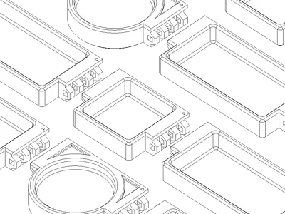
Modules
This is a list of a few organizer modules that I initially created to hold the most commonly used tools. I had to stop or I'd never publish. More will be coming.
Rectangular Hole Modules
| Number of Holes | Hole Dimension Variants |
|---|---|
| 1 | 14mm x 30mm 20mm x 30mm |
| 2 | 14mm x 30mm |
| 3 | 14mm x 30mm |
| 5 | 10mm x 30mm |
Round Hole Modules
| Number of Holes | Hole Diameter Variants |
|---|---|
| 1 | 20mm 30mm |
| 6 | 10mm 12mm 15mm |
| 10 | 10mm 12mm 15mm |
Square Hole Modules
| Number of Holes | Hole Dimension |
|---|---|
| 12 | 10mm x 10mm |
| 21 | 10mm x 10mm |
Hexagonal Hole Modules
| Hole Width Variant |
|---|
| 5mm |
| 7mm |
Round Bin Modules
| Diameter | Depth Variants | Curved Bottom |
|---|---|---|
| 30mm | 16mm | No |
| 50mm | 16mm | No |
| 70mm | 16mm 36mm | No |
| 70mm | 16mm 36mm | Yes |
| 90mm | 16mm 36mm | No |
| 90mm | 16mm 36mm | Yes |
Rectangular Bin Modules
| Length Variants | Width | Depth | Curved Bottom |
|---|---|---|---|
47.5mm 71.25mm 95mm | 35.5mm | 16mm | No |
67.6mm 71.25mm 95mm | 35.5mm | 34mm | No |
50mm 75mm 100mm | 50mm | 16mm | No |
47.5mm 71.25mm 95mm | 34.5mm | 16mm | Yes |
Additional Modules
Here are additional modules that have been added after publishing the initial modules.
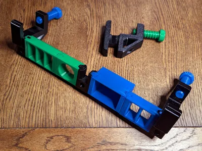
Module Mounting Clamps
The mounting clamps are used to attach the modules to the table's edge. There are four different sizes, 50mm x 30mm, 50mm x 44mm, 85mm x 30mm and 85mm x 44mm. There are three different mount clamp types for each size, left end, right end and mid support. They also have holes in them so that they can hold tools like screwdrivers or Allen wrenches.
Locking Pin
I wanted a way to connect the modules together without having to resort to buying additional hardware (screws, nuts, pins, magnets). Something I could print with no supports and be strong enough to hold the modules together but still be fairly easy to remove. Positioned in a way that it wouldn't fall out. This led to the design of the “L” shaped locking pin.
Because of the tight tolerances with the locking pin hole and variations with filament composition, you may have to adjust the height of the locking pin for the perfect fit.
Instructions
Adding a module
1. Orientation:
|

|
2. Connecting the Module:
|
 |
3. Locking the Connection:
|  
|
4. Completing the Connection (Repeat for the Other Side):
|
 |
How to remove the locking pin using the "Locking Pin Removal Tool".
1. Locate the Release Point Find the square hole on the front of the module where the locking pin is located. |
 |
2. Insert the Removal Tool Take the Locking Pin Removal Tool and insert its pointed end firmly into the square hole. Push until the removal tool is flush with the module's surface. |
  |
3. Remove the Pin In most cases, the locking pin should be dislodged by inserting the removal tool and pop out the other side of the module. You should then be able to remove it by hand. If it's held too tightly, then use the “T” indentation located on the top side of the tool to latch onto the locking ping. Wrap your fingers around the T-bar then pull the pin out .
Note: If the locking pin is still not budging after using the Locking Pin Removal Tool then use a 4mm Allen wrench and a hammer to dislodge it. You could tap on the Locking Pin Removal Tool gently but be careful as you may break the tool tip.
| 
|
Comment & Rating (19)