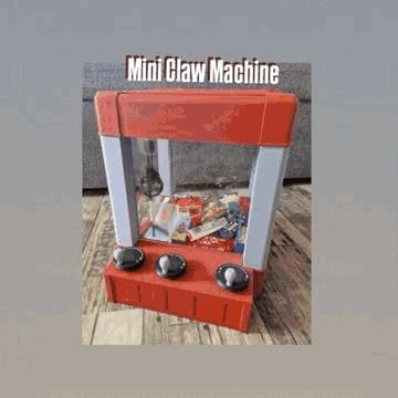
Mini Claw Machine


Print Profile(4)


Bill of Materials


Description
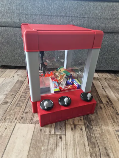
🎮 Mini-Claw Machine – Fully Mechanical, Fully Functional
This Mini-Claw Machine is a fully mechanical claw game – completely without electronics, without motors, without cables
The goal was to create an arcade game that anyone with a 3D printer can build, without any specialized knowledge in electronics or programming
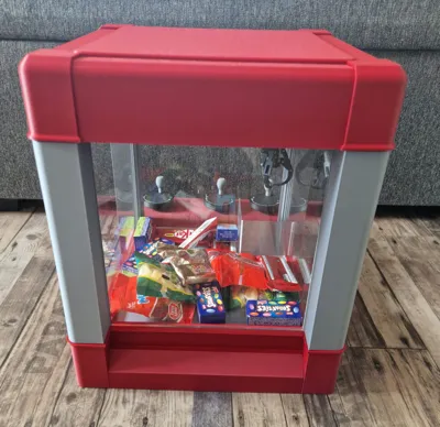
The machine is controlled entirely manually via three cranks:
- Crank 1 and 2: Move the claw forward/backward and right/left
- Crank 3: Raises and lowers the claw arm
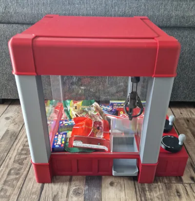
⚙️ How the Gripping Mechanism Works:

When the claw is moved upwards via Crank 3 and pressed against the upper stop, an internal spring is tensioned. The optimal tensioning point is front left – at the retrieval area, where the construction is most stable.
In other areas, the geometry might be tighter, making the mechanism harder to tension or potentially causing damage – some caution is advised here
After tensioning, the claw can be moved freely in space. When subsequently lowering, the trigger is activated by contact with an object, and the claw automatically closes.
Solid objects like small candies (e.g. Smarties, Kinder bars, small packages) can be reliably gripped. For soft or flexible objects, depending on their shape, it might be necessary to lower the claw with a bit more momentum to ensure triggering ( see GIF )
The mechanism was entirely self-developed and tested multiple times. Currently, in this version, it is fully functional, as long as the above instructions are followed
In the future, there are plans to design further claw variants, e.g. for loose objects or more delicate parts
Change:
- Print profile for casing parts; Plate 8 had 1 additional part (219) added, as 4 are needed
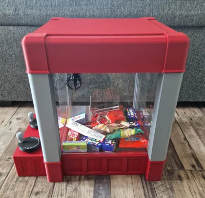
📐 Dimensions:
- Overall dimensions: approx. 345 × 275 × 320mm (L × W × H)
- Interior (play area): approx. 195× 195mm (L × W)
📄 Instructions & Assembly
A compact assembly guide is available as a video, showing all steps of the assembly
▶️ YouTube link here
Boost Me (for free)
If you like the model, I appreciate a boost or a rating.
This helps to make more high-quality designs possible. Thank you!
Claw – Assembly Instructions (Step-by-Step with Pictures)

1. Parts Overview
As shown in the picture, all necessary components for the initial steps are depicted here. This is not the complete parts list for the entire claw, but only the components needed to start.
Additionally, it can be seen that for the first steps, pins of different heights are used, while in later stages, identical pins are always used
2. Assemble Lower Part + Knee Joint
The lower main part and the lower element of the knee joint mechanism are aligned correctly – as shown – and connected with the long pin through the designated openings
3. Attach Upper Main Part + Side Arms
The upper main part is connected with two identical side parts using a central pin.
It is important that this pin sits centrally and the two side holes remain free – further connections will be made there later
4. Connect Knee Joint
The upper and lower knee joints are now pushed together so that a small pin sits centrally in the connection. This allows the two parts to move against each other
5. Check Trigger Position
The picture shows how the small trigger pin on the lower knee joint must be correctly aligned. This position is crucial for the subsequent gripping process to be triggered correctly

6. Insert Trigger
Now the trigger is inserted from below into the corresponding opening
7. Engage Trigger – With Caution!
The trigger must click into place on one side. Extreme caution is advised – the part is delicate and can break easily.
It is recommended to use a thin tool (e.g. screwdriver or spatula) to gently bring the mechanism into position.
It worked for me on the first print. On the second print – after re-printing – the part broke slightly. So: work with care. The part may need to be reprinted if necessary
8. Mount Claws (Lower Claws)
Now the three gripping claws are attached one after another to the lower main part:
A total of nine identical pins are available for this
First – as shown in the picture – one claw is mounted with one pin
Then the other two claws are attached in the same way, each with one pin, to the remaining sides
9. Insert Spacers
The three spacers, which connect the claws to the upper main part, are now inserted – as shown in the picture.
The connection is made on each side, top and bottom, with one pin each – a total of six pins (the remaining ones from the nine).
This creates a movable connection between the claw and the main body
10. Mount Weight and Stop
The upper weight part and the stop, which serves as the endpoint when cranking up, are attached as shown.
The part has an M10 thread onto which standard M10 nuts can be screwed.
For fixation, simply apply a few drops of superglue,

glue neatly and let dry thoroughly
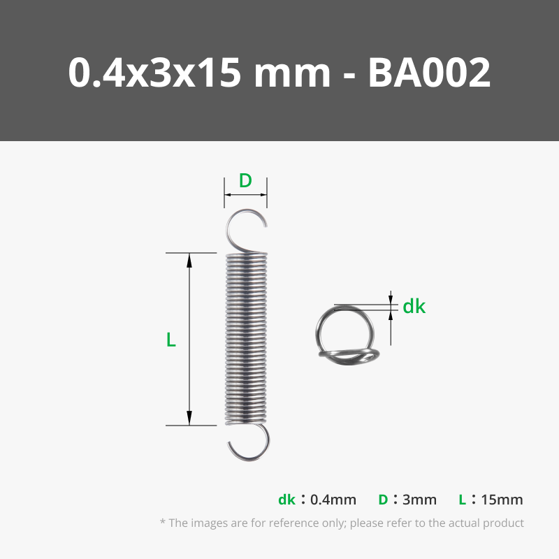
11. Insert Springs
Now the return springs are inserted.
The spring tension allows influencing how strongly and reliably the claw closes when lowering. Further fine-tuning is possible later
12. Screw on Nuts
As shown, the M10 nuts are now screwed onto the glued thread above – these serve as a counterweight for the mechanism
13. Thread Cord (Bottom)
A strong, tear-resistant cord is used.
The cord is guided from top to bottom through the housing, pulled through the small eyelet at the bottom, and securely knotted there.
Caution: The cord is under considerable tension, so please do not use weak material
14. Guide Cord Through Top
The cord is guided upwards again, pulled between the two guide rollers, and integrated into the upper mechanism
15. Attach Cord to Spool
As shown in the last picture, the cord is wound onto the spool in exactly the correct direction and securely knotted there.
Important: The winding direction must be exactly as shown in the picture – otherwise the mechanism can pull crookedly or jam
🧾 Bill of Additional Parts:
- Ball Bearings: MR128ZZ (8×12×3.5 mm) – 44 pieces 🔗 https://amzn.to/456nZVz
- Tension Springs: 12–15 mm × 3 mm × 0.3–0.4 mm – 2 pieces
- M2×8 mm Screws – 9 pieces 🔗https://amzn.to/4pM9miG For all screws!
- M3×8 mm Screws – 62 pieces
- M3×10 mm Screws – 23 pieces
- M3×12 mm Screws – 8 pieces
- M3×20 mm Screws – 8 pieces
- M10 Nuts – 2 pieces
- Plexiglas: 200×200×5 mm – 4 pieces 🔗 https://amzn.to/4pPL3Au
- Piece of strong cord (approx. 300 mm, e.g. nylon or braided line)
Note: I participate in the Amazon Partner Program. All Amazon links are affiliate links. If you purchase through these, I receive a small commission – at no extra cost to you. Many parts are also alternatively available directly in the Bambu Lab shop – just choose what suits you best.
License
You may create derivative works based on this object, provided that all such derivative works are published exclusively on the MakerWorld platform and include proper attribution to the original creator. You may not share, upload, host, distribute, or publish this object—or any derivative work of this object—on any other digital platform, marketplace, or distribution channel. Commercial use of this object and any derivative works is strictly prohibited. This includes, but is not limited to, selling, renting, sublicensing, or using the object in any context in which you receive monetary compensation or other financial benefits.
Comment & Rating (160)