Bambu chamber heater


Print Profile(1)

Bill of Materials


Description
Boost Me (for free)
Please leave a boost for all my work I put into the instructions and the design + lost material due to iterations to perfect it.
I wanted to make a simple add-on heater for enclosed Bambu Labs printers like the X1C and P1S.
Existing designs often fit the heater into the printer's tight chamber, which means the very hot air outlet is too close to the original plastic parts of the printer—sometimes only 10mm away. Although these parts can handle some heat, temperatures above 150°C (which this heater reaches) are not ideal for them. Also, in many designs, the heater controls are inside the chamber, making them hard to access while printing.
This design avoids all the problems I've seen in other solutions. My design extends the printer's front by adding a 65mm section.
Disclaimer:
By modifying your printer, you acknowledge that you do so at your own risk. The designer (me) cannot be held responsible for any severe issues, malfunctions, or damages resulting from these modifications.
Part list:
- W3230 AC110-230V Thermostat: https://nl.aliexpress.com/item/1005005916644628.html
- AC converter 85-265V to 24V DC (2A): https://nl.aliexpress.com/item/1005006062380734.html
- PTC heater - 350W - 230v heater-24v fan (you can take lower wattage but it'll take longer before the setpoint in the printer is reached): https://nl.aliexpress.com/item/1005003140673176.html
- Silicone wire black (2m) and red (1m), 18AWG.: https://nl.aliexpress.com/item/1005006064722016.html
- 2x Wago 3 or CMK-413 connector: https://nl.aliexpress.com/item/4001363392242.html
- 1x Wago 4 or CMK-414 connector: https://nl.aliexpress.com/item/1005007592304757.html
- 12x M3 heatset inserts. See link bambushop.
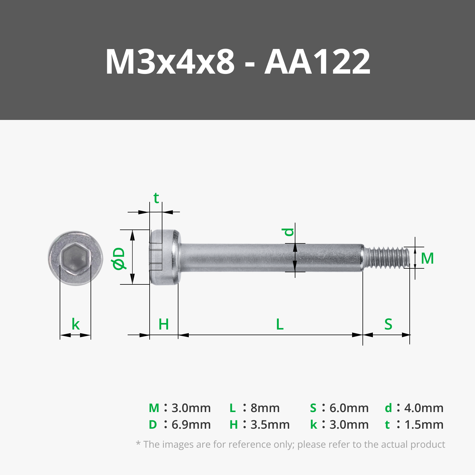
- 6x M3x8 screws
- 2x M3x6 flat head screw (came with your printer and probably you didn't use them yet)
- Powercord, min 0.75M (I recovered mine from some broken appliance)
- 500g ASA or ABS
- Aluminium tape or just foil (not as clean looking)
- 2x M5 nut or Tnut + 2x M5x10 (or longer)
Instructions:
- Print in ASA or ABS or any material that has a vicat softening point above 75°C.
- Create the frame:
- fill a shallow lid with 1-2mm depth of acetone to glue the parts together. (if printed in another material you'll need to use glue)
Dip the surfaces that will meet both in acetone, lay them on a glass, tile, wood flat surface (surface that will not interact with the acetone vapors) and press the parts firmly together for ±20 seconds (till you can't move the parts vs each other freely).

Make sure the still flexible vertical walls nicely lign up!

Once the complete frame is made, you can add the connectors, I used a cheap brush to acetone the “channels” of the connectors only and slid them in place.

Press the vertical walls firmly to the connector while the acetone cures.

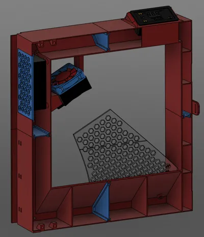
Now finish the frame by adding the 12x M3 heatset inserts: 4x for the door, 4x for the PCB attachment, 2x for the heatshield and 2x for the lock bolts (magnetic closure of the door). See highlighted locations in below snapshot.

Assemble the heater => TIP: first preassemble the nuts with a loose bolt as the nut will be quite difficult to reach once the wires of the heater are in place.
Route the wires of the heater through the holes, the excesive wire that can't be fitted through can be tucked away in the bracket.

- Cabling:
- Cut some silicone wires to correct length and crimp terminals (without plastic end to it):
- 1x 6 cm black
- 2x 40cm black
- 1x 30cm black
- 2x 10cm red
- 1x 40cm red
Connect the thermistor with the thermostat: remove the backpanel of the thermostat to access the connector.

Connect the wires on the thermostat, the wires should be able to go straight down or you want be able to install it into the frame (I removed the plastic from my crimp terminals to be able to do this):

Guide all the wires from the thermostat (start with the thermistor) through the hole and the channel:

- Fasten the PCB in the provided location.
- Route the powercable from the bottom of the frame and fix with 3 zip ties in the provided area.
Route the thermistor to the backside of the frame through the hole in the topleft corner:

Now finish the wiring:

- Test the wiring by connecting to the main power before you assemble it all to the printer…
- Cut some silicone wires to correct length and crimp terminals (without plastic end to it):
Remove the glass door from the printer by removing the 4 flathead screws.

- Now assemble ther frame onto this location with the same screws (Do not use the rubber washers here, keep them on the glass door)
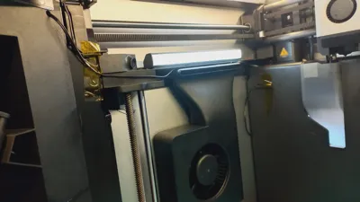
Route the thermistor to the back of the printer, you can tuck away the excessive cable between the opening on the back. Make sure the cable doesn't go into the circled area as the print head travels here.

Slide in the grid next to the buck converter and assemble the glass door: slide the door latch through the provided opening and fasten the 4 bolts with the rectangular plastic washer onto the rubber grommets.

Assemble the heatshield (wrap aluminium foil around it or it won't work). => otherwise the door gets VERY hot!

Now assemble the flathead bolts for the magnetic closing: test the bolts if they are magnetic!

- DONE !!
- Turn on the heater ±10 minutes before you start printing => the thermostat of the Bambu printer lags a lot vs the one from the heater due to other position in chamber and other thermal mass. (after 30 minutes they should be close to each other)
- I use 40°C setpoint for PETG, 60° for ASA.
License
You shall not share, sub-license, sell, rent, host, transfer, or distribute in any way the digital or 3D printed versions of this object, nor any other derivative work of this object in its digital or physical format (including - but not limited to - remixes of this object, and hosting on other digital platforms). The objects may not be used without permission in any way whatsoever in which you charge money, or collect fees.
Comment & Rating (0)