
Pegboard Wall Mounting Solution (C45 Rail)

Print Profile(6)



Description
This solution is suitable for my designed "infinite pegboard assembly":https://makerworld.com/en/models/932107
It is also suitable for pegboards with reserved M4 holes (M4 hole center distance is 25mm)
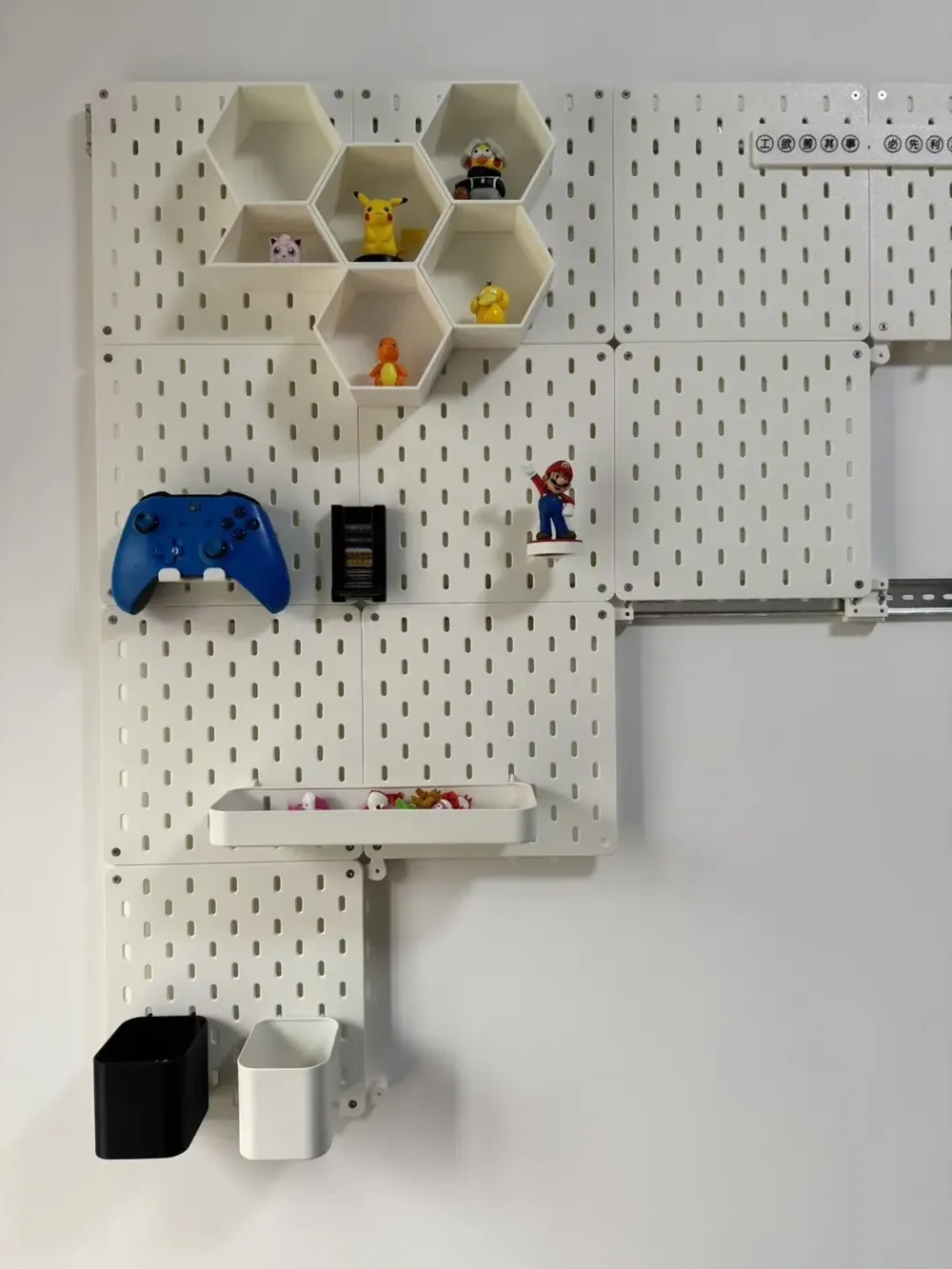
This solution can be installed on any flat wall surface, and the overall schematic diagram is as follows:

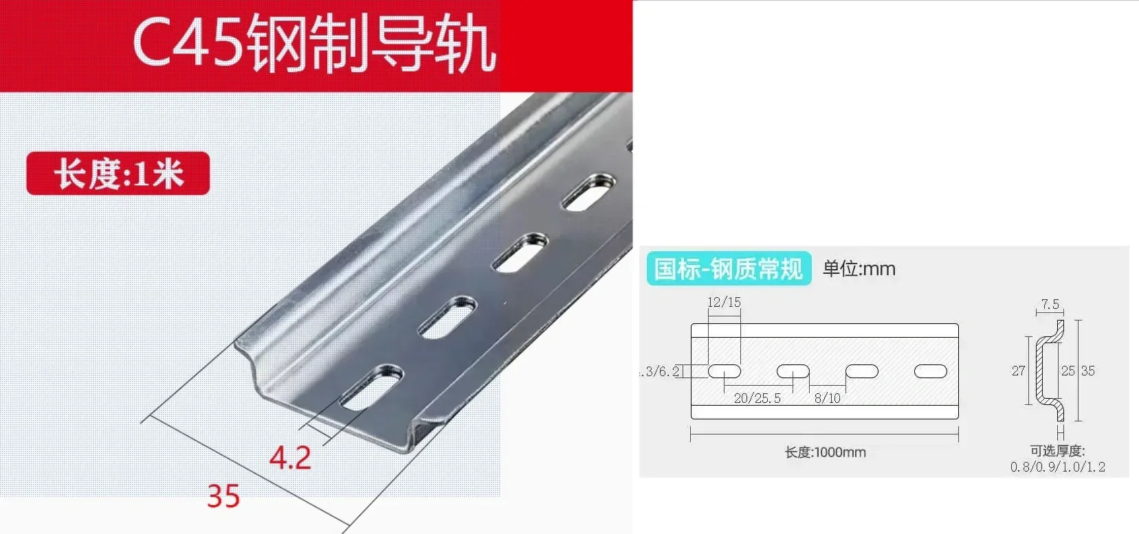
The main hardware component is the C45 DIN rail, just buy the national standard model.
Purchase length as needed, if it's too long, buying several segments and splicing them together will yield the same result.
The C45 DIN rail has a height of 35, an inner depth of 7.5, and the thickness I used is 1mm (the model's rail slot thickness is reserved at 1.4mm, other thicknesses can also be chosen), other parameters are optional
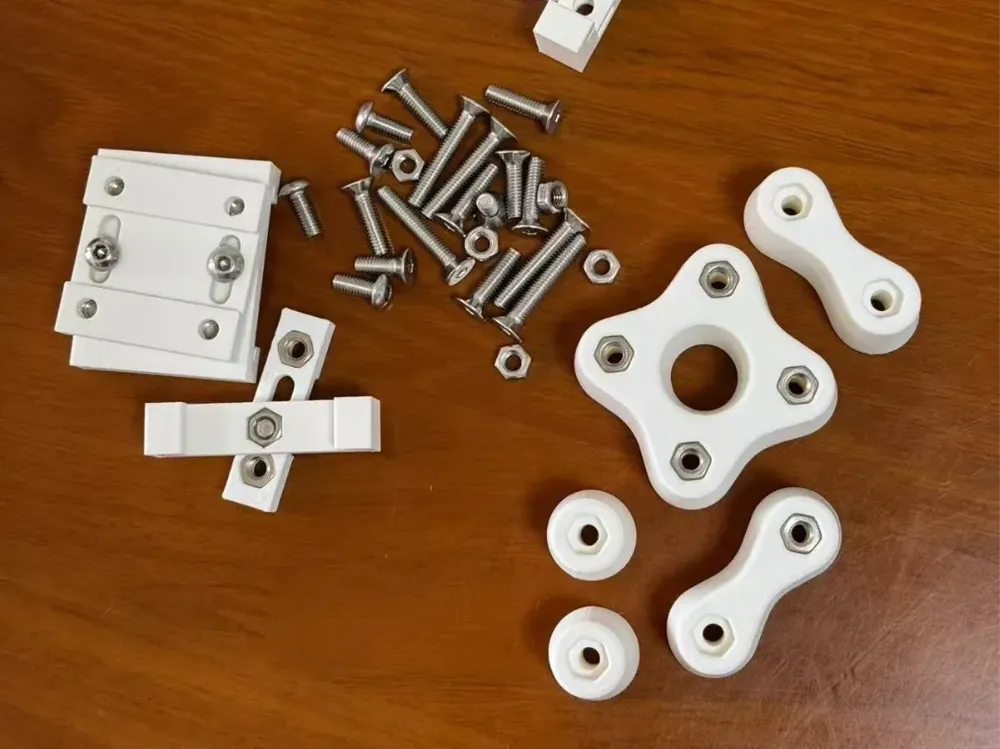
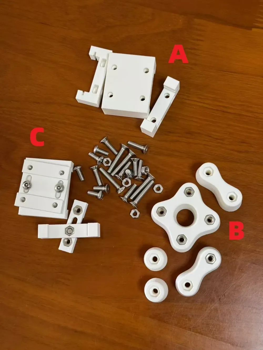
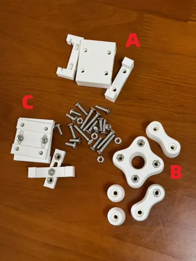
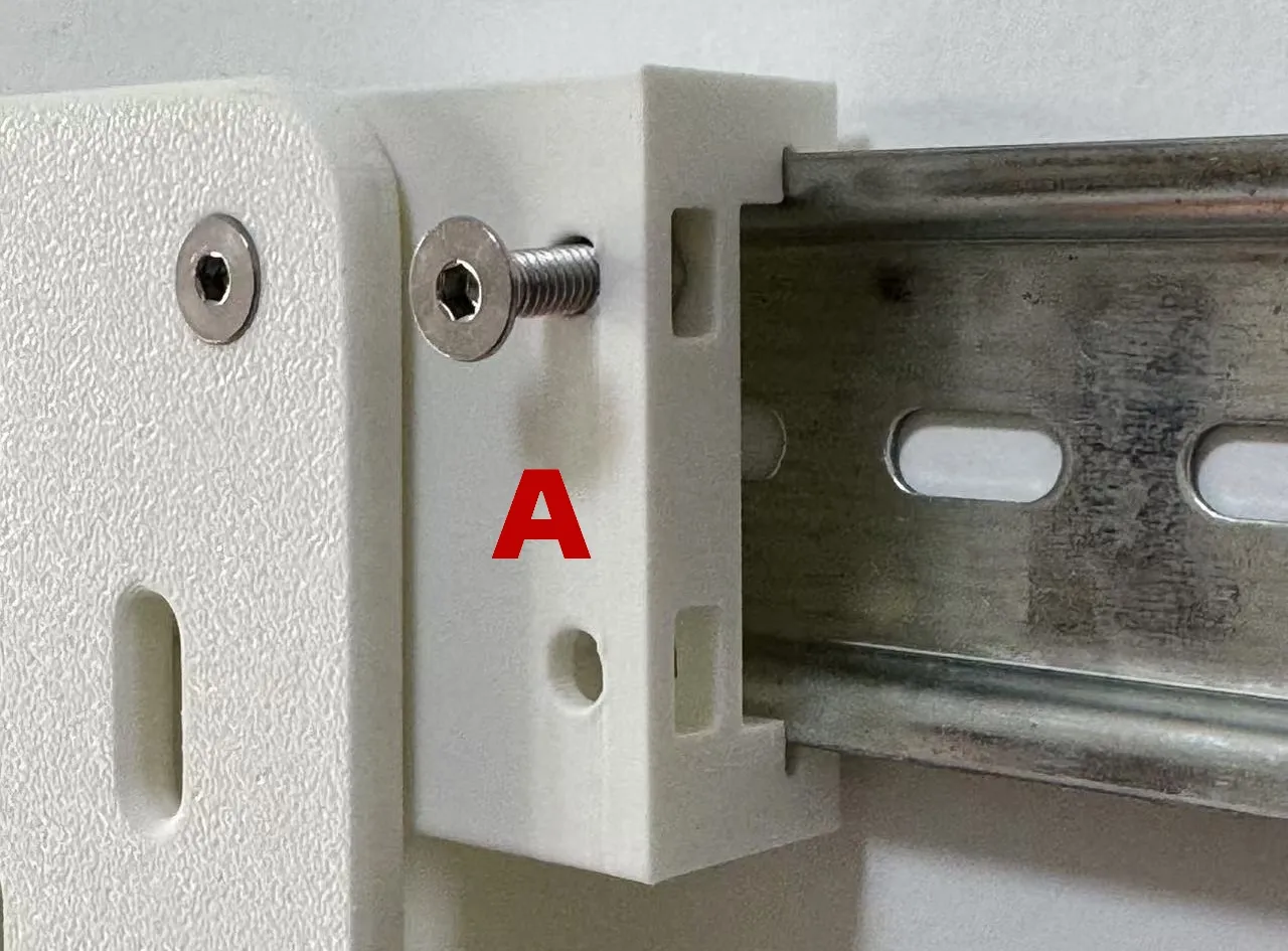
Module A is used with DIN rail, M4x16 countersunk screws, and M4 nuts, and can only be installed on the top layer. If module C is not installed, the entire load bearing will be on this layer.
The pegboard is installed in the upper holes of module A, while the lower holes are redundant for symmetrical design and are not actually used
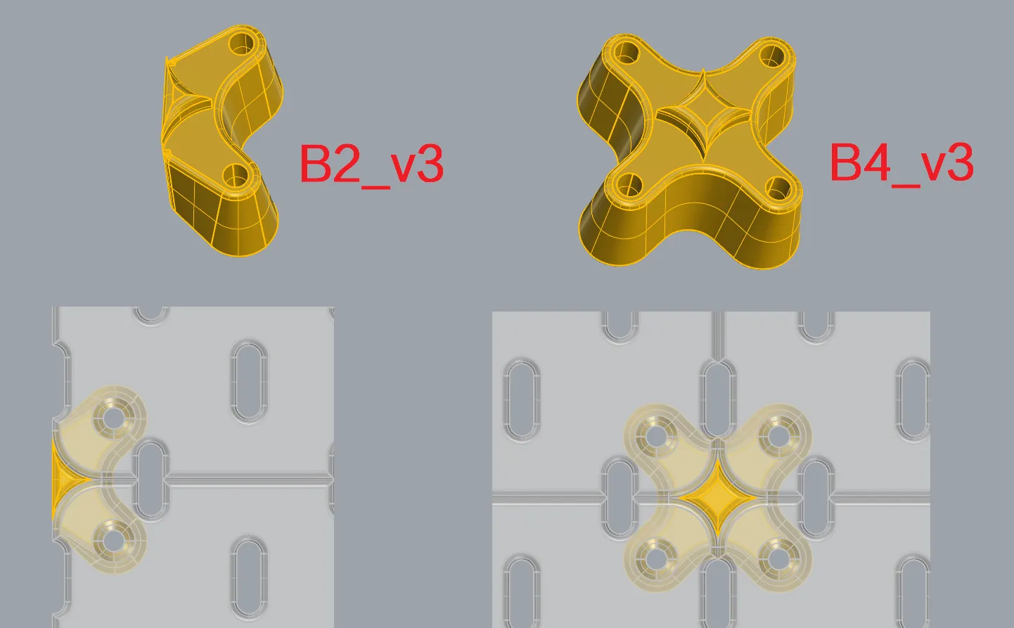
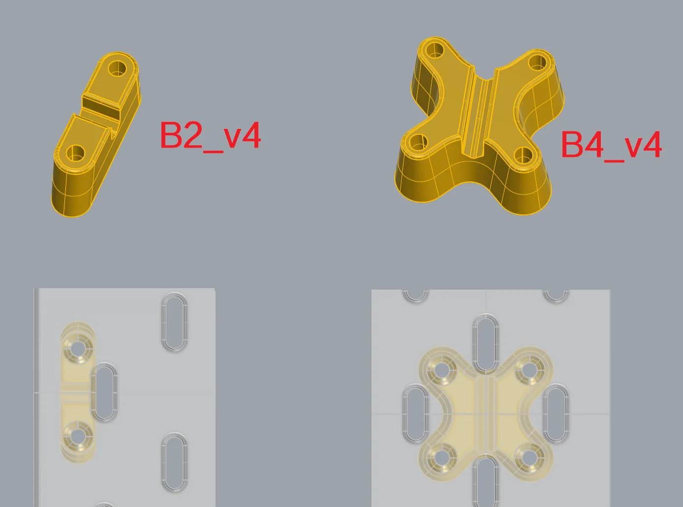
Module B is used with M4x25 countersunk screws and M4 nuts, serving to connect the pegboard to the wall
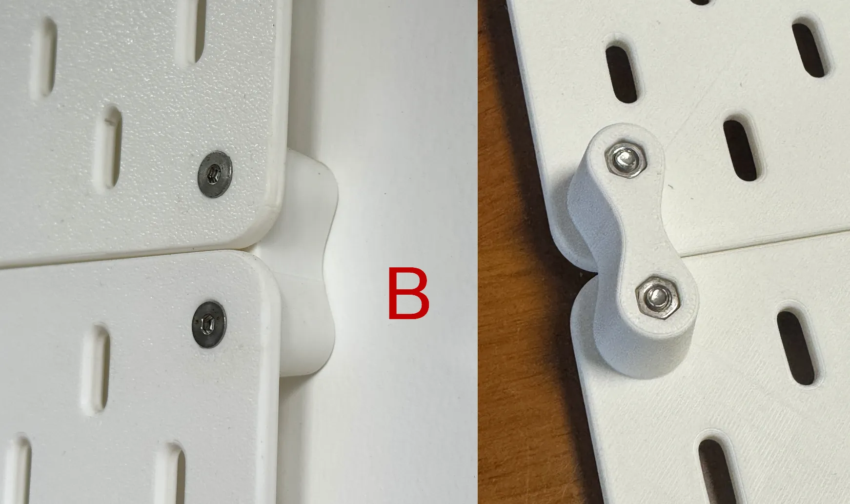
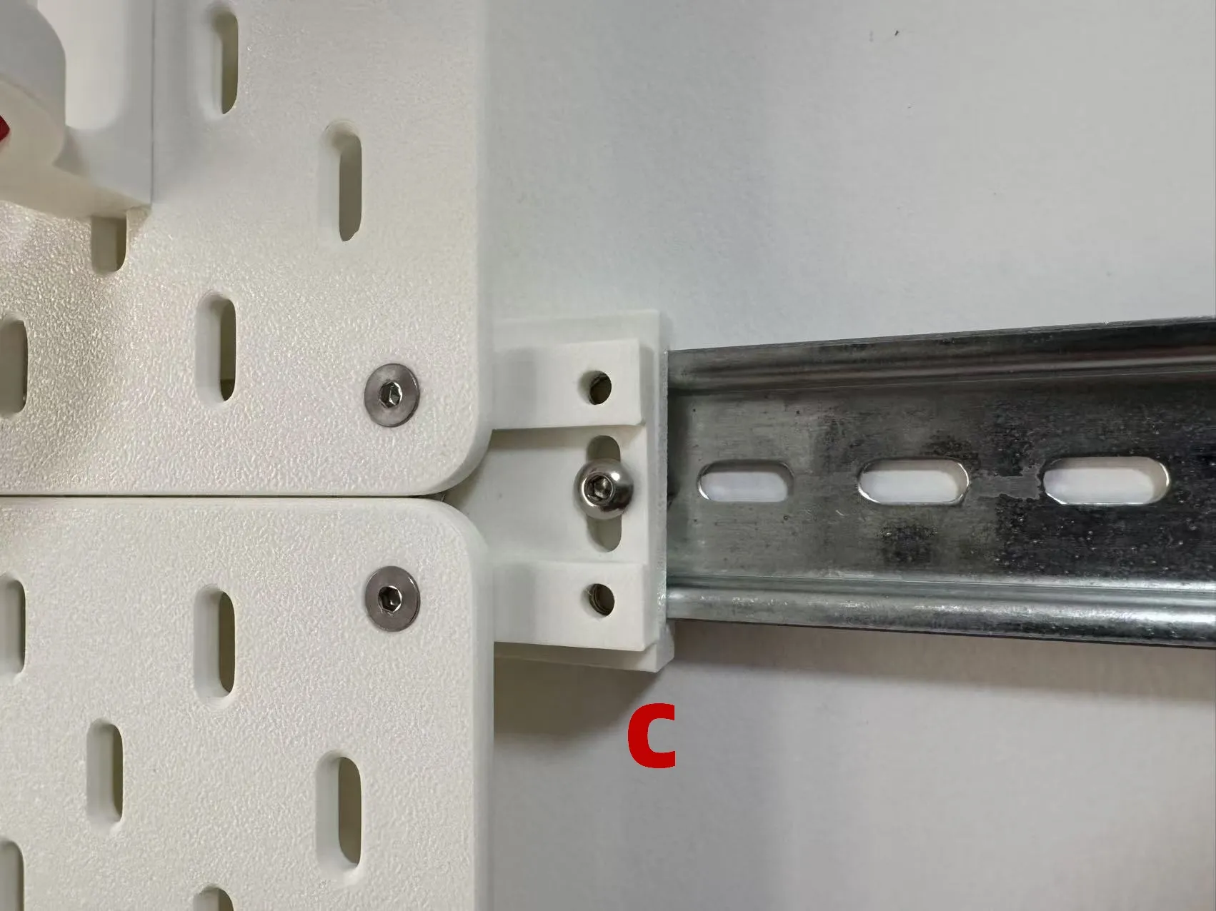
Module C is used with M4x10 round head screws, M4x12 countersunk screws, and M4 nuts, serving to reinforce and distribute the load.
Layer C is not essential; if only 2 or 3 rows are installed, AB or ABB schemes can be chosen. When there are too many rows, it is recommended to use layer C every other row.
When installing the DIN rail for layer C, the centerline of the rail is positioned as the boundary line between the two plates. The two lines do not need to coincide perfectly; there is a 14mm tolerance height
After installation, the pegboard's distance from the wall is 20.4mm
Summary of required hardware components:
C45 DIN rail,
M4x10 round head screws,
M4x12 countersunk screws,
M4x16 countersunk screws,
M4x25 countersunk screws,
M4 nuts.
50 of each type of screw and 100 nuts will cover a large area
2025-02-02: Added Module B3.
2025-04-14: Adjusted Module A2 size so it does not obstruct adjacent holes.
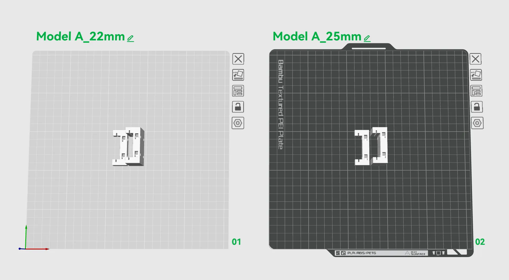
2025-06-22: Added Module A with 25mm spacing; if the lower DIN rail is precisely positioned, it can replace Module C.
2025-11-18: Added Module B v2 version, suitable for use with self-tapping screws for reinforcement.
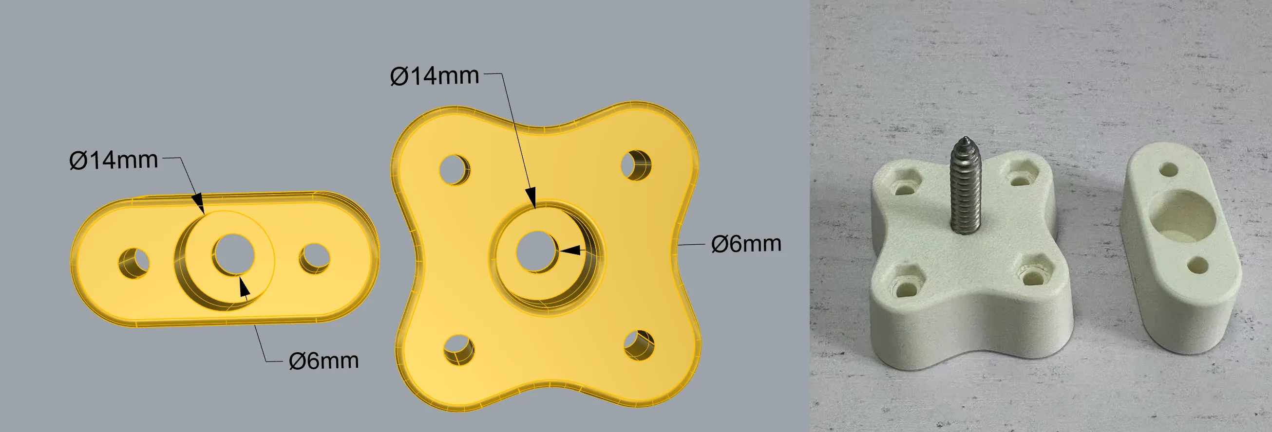
2026-06-28: Added Module B v3 and v4 versions, which can solve the interference problem of the full-hole version.
Boost Me (for free)
If my model helps you, please consider boosting me. It's free for you, but it helps me a lot, thank you very much!
License

You shall not share, sub-license, sell, rent, host, transfer, or distribute in any way the digital or 3D printed versions of this object, nor any other derivative work of this object in its digital or physical format (including - but not limited to - remixes of this object, and hosting on other digital platforms). The objects may not be used without permission in any way whatsoever in which you charge money, or collect fees.


Comment & Rating (442)