Dual-Axis Adjustable Microscope Stand


Print Profile(1)
Description
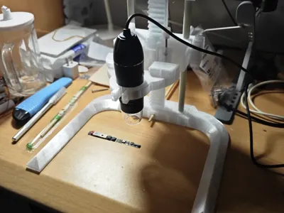
Suitable for inexpensive microscope stands, the original design was affixed to a wooden board. I have retained this design while adding a new base, connected via an M5x40mm screw and nut. Alternatively, as I did, you may use a chopstick (or straight wooden dowel) for this purpose. Beyond this, you will require the following items:
Parts List
2 x 9.6mm x 210mm steel rods/glass rods (optional)
2 x 9.6mm x 150mm steel rods/glass rods (optional)
(These can also be 3D printed; the second plate contains the rods. The Fusion 360 model is publicly available. Adjustments can be made for different rod dimensions before printing.)
3 x M3x30 screws (required)
3 x M3 nuts (required)
2 x LM10UU linear bearings (optional)
If attaching to a wooden board, you will need 2 x 3x30 wood screws
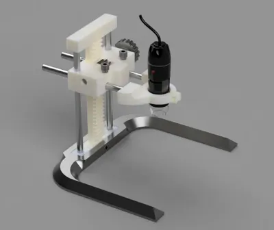
Assembly Instructions
Connect the 21cm rod and rack component to the coupler, securing the rack using M5 screws and nuts. Slide the carriage onto the rod and rack.
Install the top coupler (cover) and secure it in the same manner as the bottom (using M5 screws). Position the gear between the two carriage arms and slide the knobbed shaft into the carriage and gear.
Attach the two rods to the clamp (consider using adhesive if the rods are loose). Finally, insert the clamp and rods into the holes in the carriage.
Assemble the M3 screws, nuts, and printed knobs, securing them to appropriate locations on the carriage to allow for position locking.

Comment & Rating (4)