
Stitch Length Adjuster V2 (Sailrite compatible)
Print Profile(2)


Description
Stitch Adjuster V 2.0
What is this
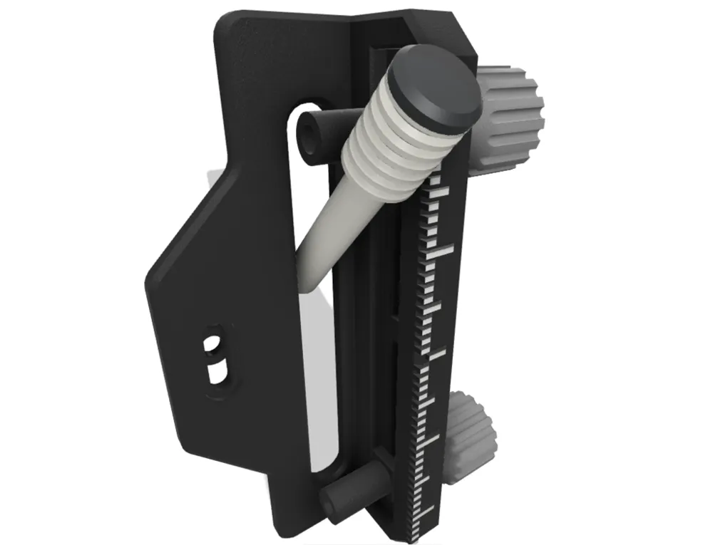
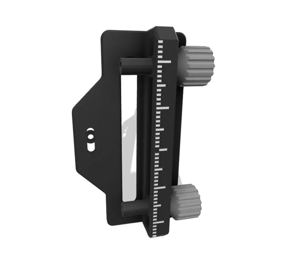
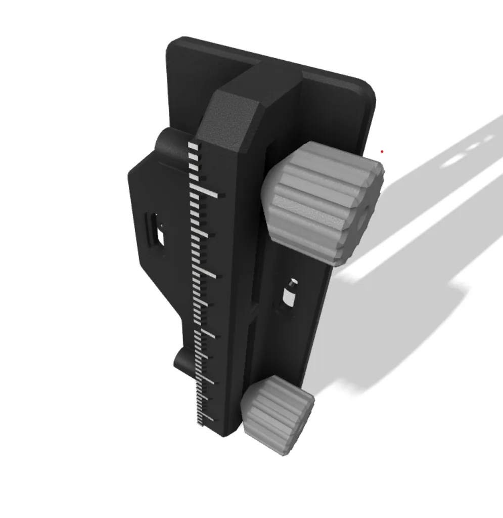
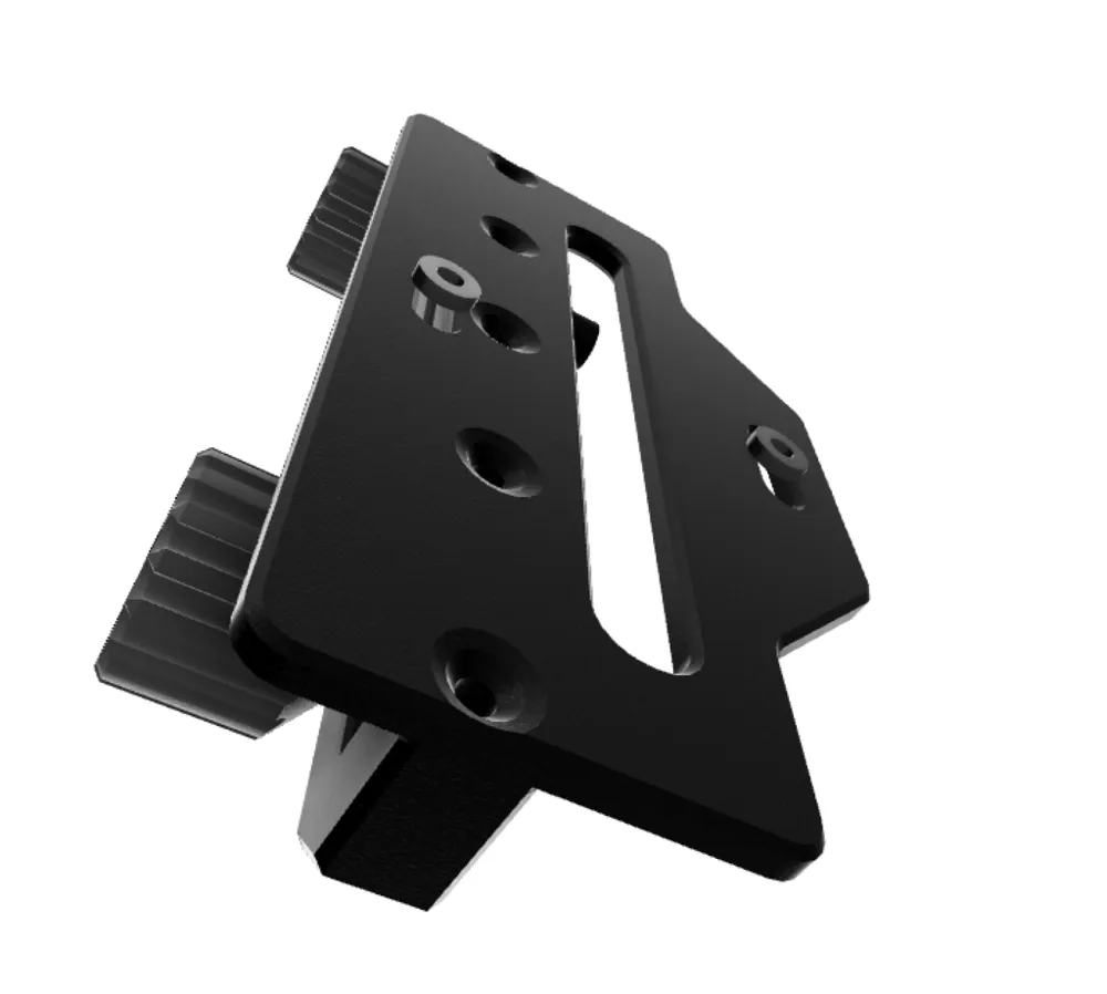
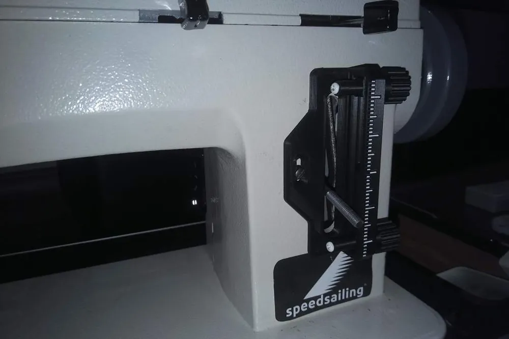
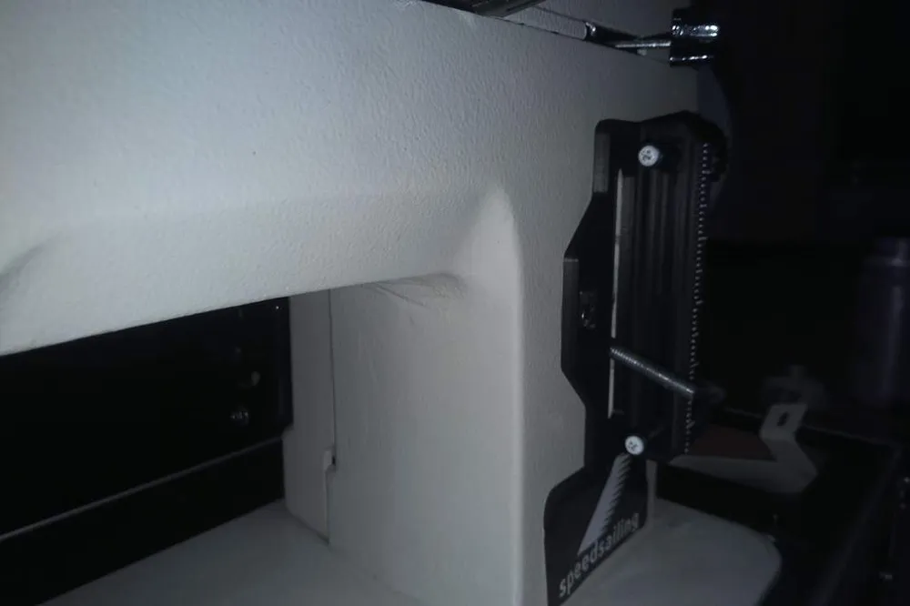
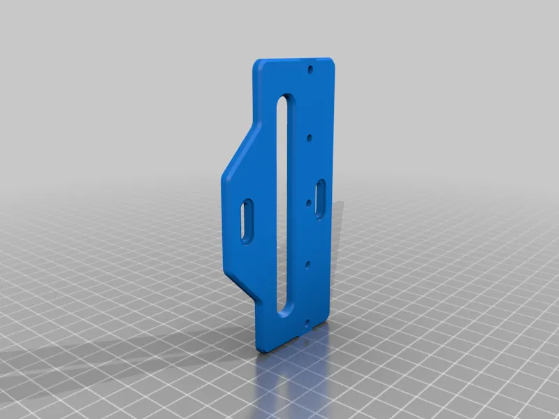
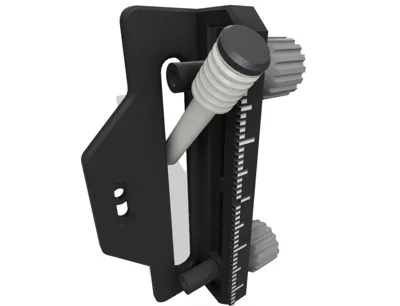
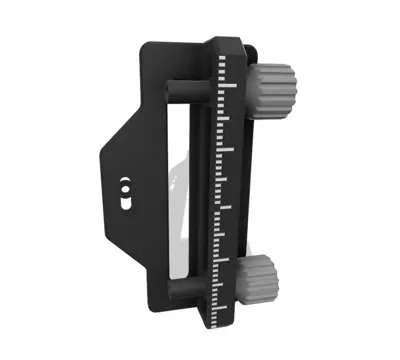
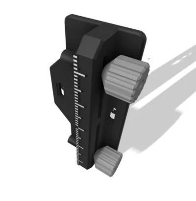
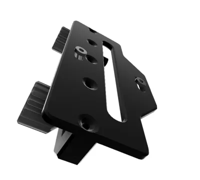
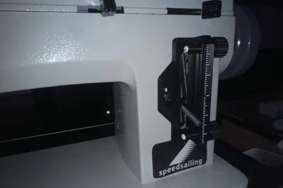
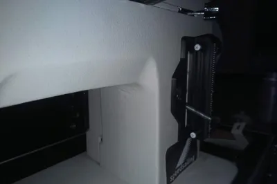
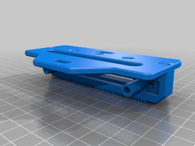
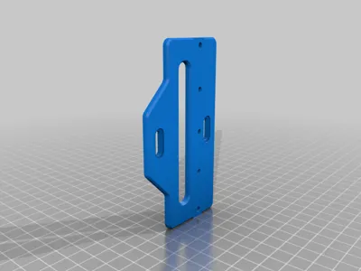
This is the second iteration of the 3D printable stitch length adjuster for Sailrite LSZ-1 (LS-1) and other common machines with drillings in this location.
Make sure you adjust the plate to be in the center. (i.e. forward 1.5 and reverse 1.5 stitches travel the same distance)
I would love to hear from you if you if you find this project interesting! Perhaps look at my other related projects.
Additional parts and tools
You will need
- two flat headed M3x30 bolts (DIN 912),
- five countersunk M3x10 bolts(DIN 963) and
- seven M3 heat set inserts with a length <= 6mm.
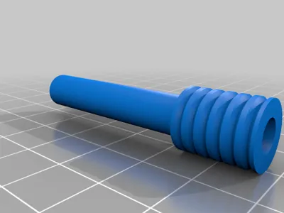
five for the rail and two for the knobs - two small m3 washers for the adjuster screws
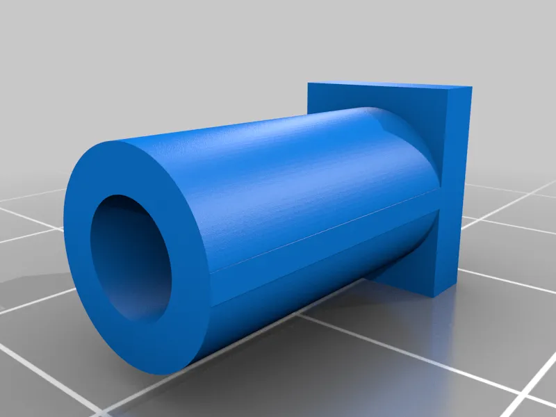
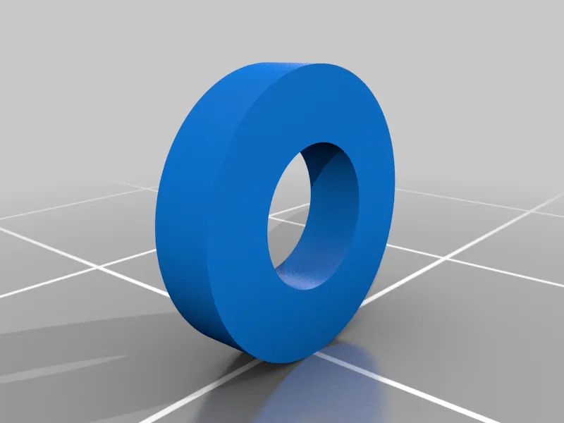
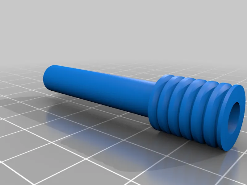
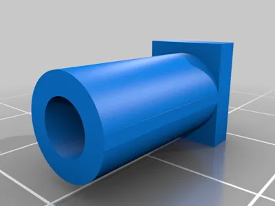
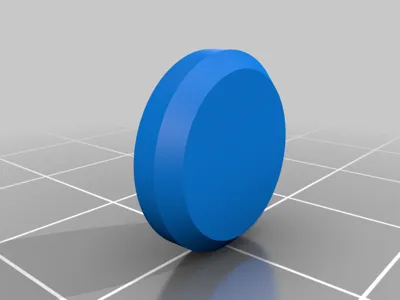
All other parts are 3D printed. This version of the adjuster works with your existing bolts. Please do not forget to print the spacers that are slotted in between the adjuster and the machine housing.
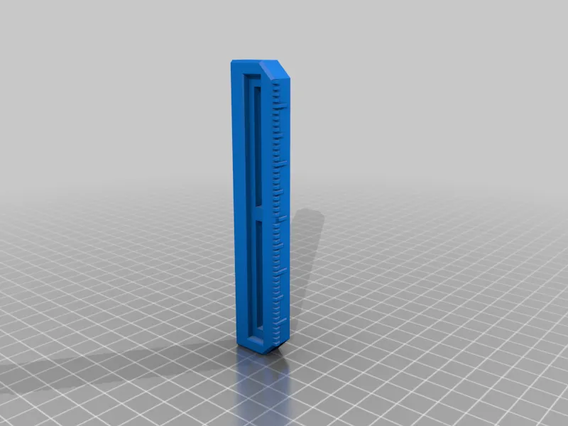
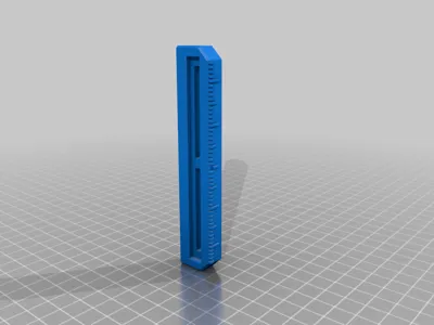
The white stripes were added using a white permanent marker.
Print settings
Printed without supports on a 0.4mm nozzle with layers heights of 0.2.
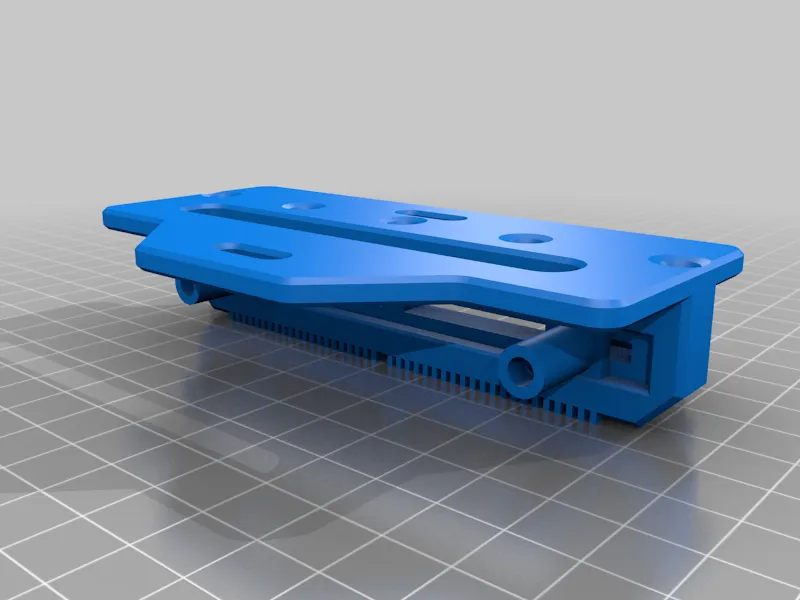
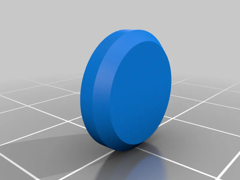
The guide track should be printed with the track facing upwards. The gradation have 45° chamfers on them and print without supports. Sliders are printed with the square side down, knobs are printed from wide to narrow. The base's chamfered screws should be facing the print bed.
Known issues partly due to 3d printer or sewing machine variances
- tight tolerances in the square inserts
- feed regulator lever rubbing against left or right edge of the part
Changing screw and insert dimensions
Without commenting on the that fact that the Whitworth system doesn't make much sense (Whoops, I did it), it is possible to change heat set insert and screw dimensions in the "Change Paramter" menu in fusion 360.
Changelog
- countersunk bolts repositioned to the underside
- slider size was increased
- guide rail was reinforced and made wider
- setbacks included in baseplate to allow reuse of original screws
- larger screw hole tolerances
- larger insert holes
- larger thumbscrews with larger grip pattern
- removed slider indicator, permanent marker could be used instead
- guide rail slot was removed and replaced with 5 countersunk screws from the rear
- overall range was increased
- spacers were added to fill the gap between plate and machine
- new gradation was added for easy adjustability
- lever was added for improved usability
*Feel free to report any issues you may be having with this print.
License



Comment & Rating (6)