
Compact Boeing 737 Overhead Panel

Print Profile(1)

Description
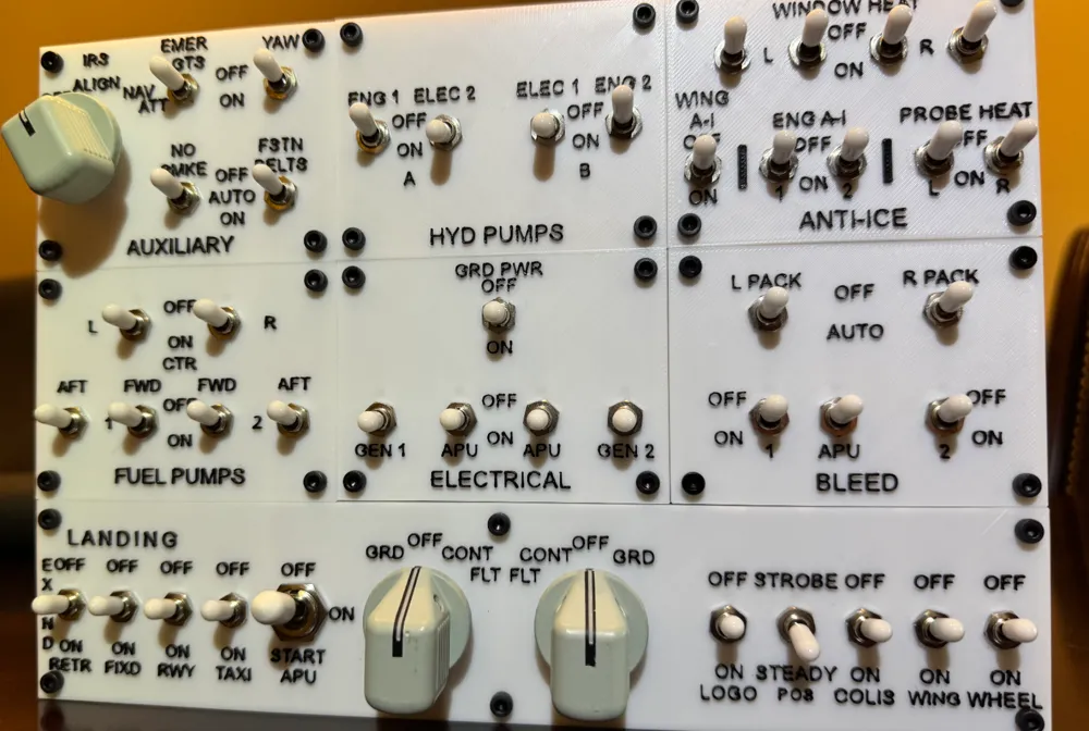
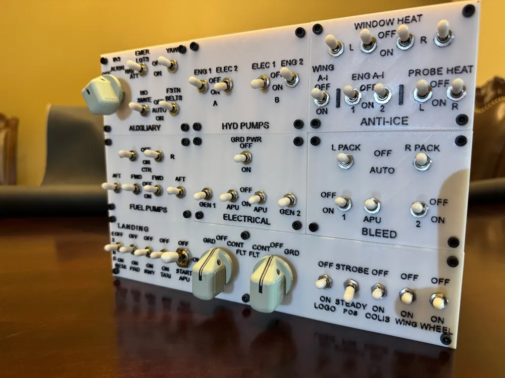
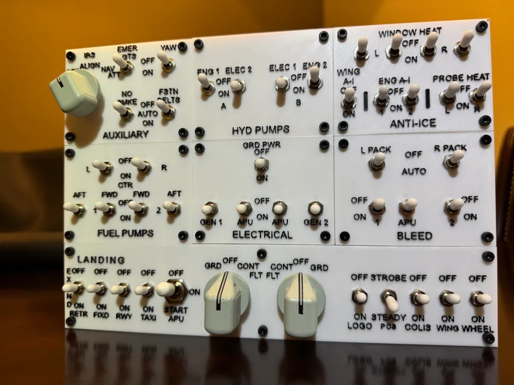
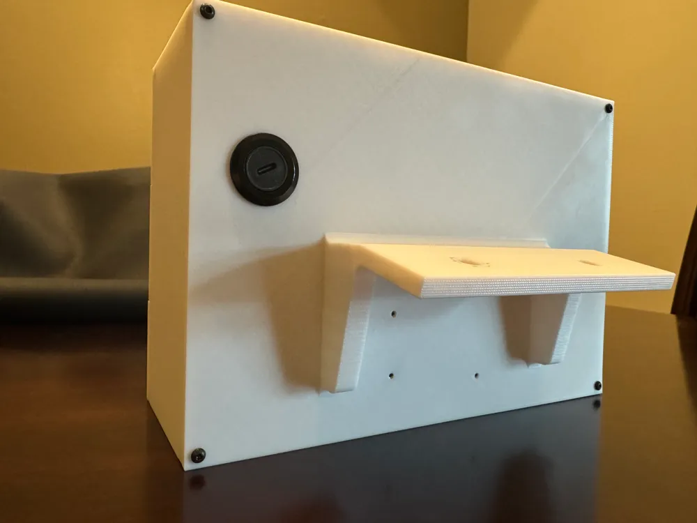
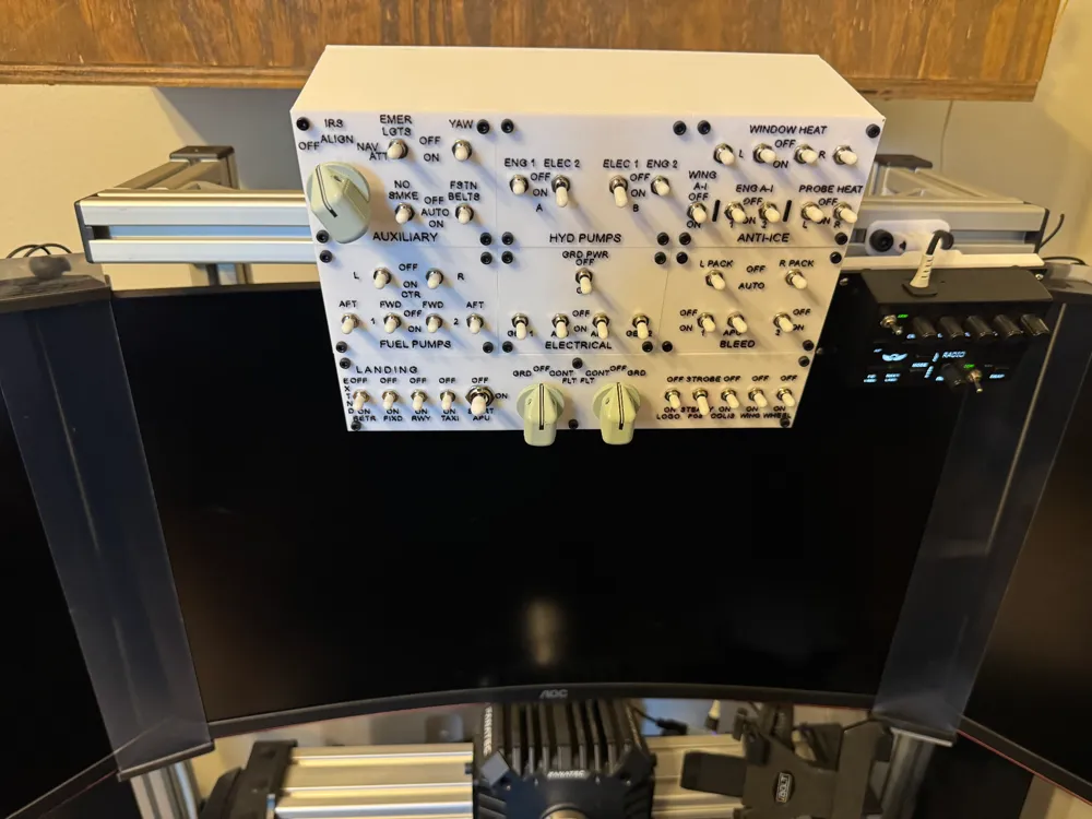
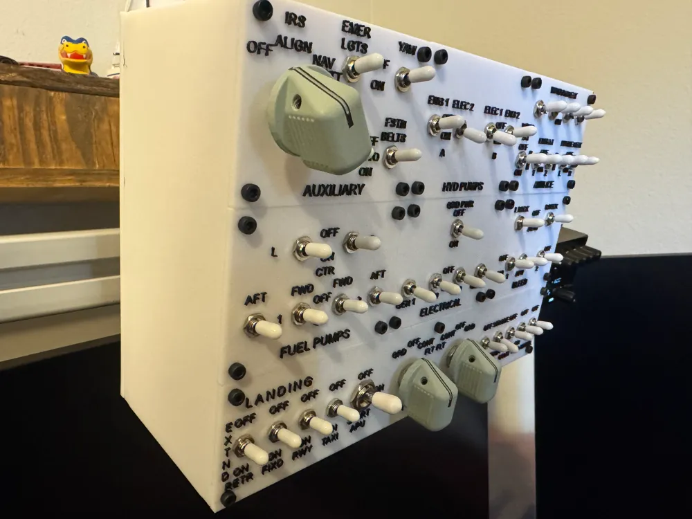
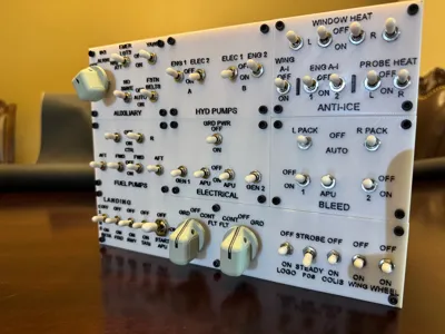
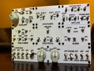
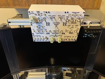
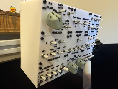
This is my design for an “essentials only” Boeing 737-800 overhead panel box I use for the PMDG 737-800 on Microsoft Flight Simulator. The purpose of this box is to mimic the real-life 737-800 overhead panel, but in a compact design and with only the essential switches needed for the majority of flights. Each section is mounted to the enclosure using hex screws and heat set inserts. The rear panel is where the Arduino mounts along with a female USB-C outlet. You'll need some basic knowledge on how to wire an electrical circuit as part of the process involving soldering wires to the switches and connecting them to your Arduino.
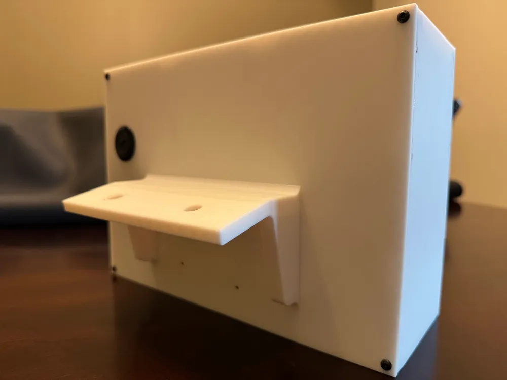
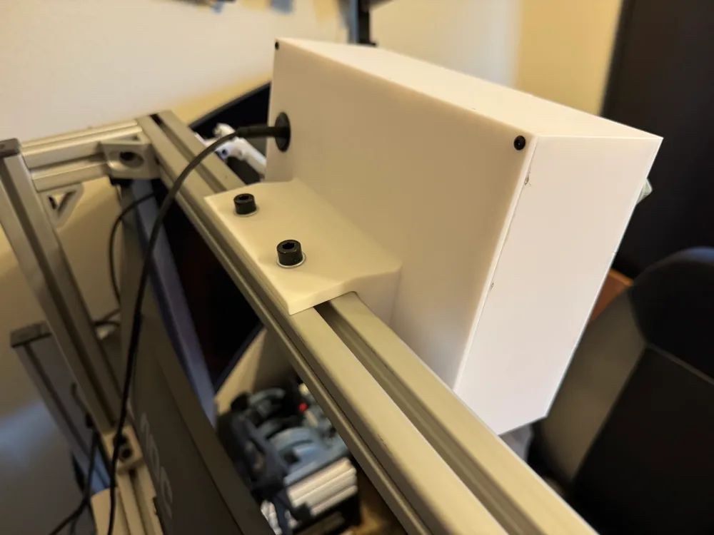
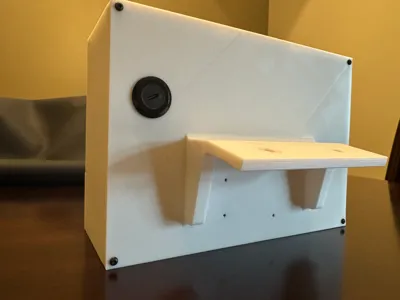
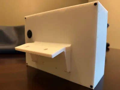
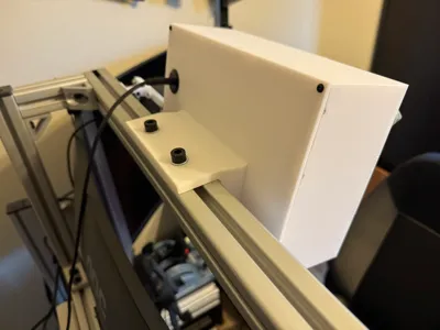
I also included a flat rear panel in the event that you don't have a sim rig to mount this to (sim rig rear panel pictured).
I use this mainly on MSFS 2020 with the PMDG 737-800, however this should work with any flight sim as long as you can program the Arduino to interact with it. I have also tested this with the default MSFS 2024 Asobo 737 MAX 8 using MobiFlight and confirmed it works, but have not used it extensively.
Below is a list of items you'll need and some basic instructions on assembly.
Switches
- 3x 1-pole 12-position rotary switches
- 3x rotary switch knobs
- 33x ON-OFF (ON-ON) small toggle switches
- 4x ON-OFF-ON small toggle switches
- 5x MON-OFF-MON momentary small toggle switches
- 1x OFF-ON-MON big toggle switch
- (Optional) 5x Small Toggle Switch Cap (Set of 10)
- (Optional) 1x Big Toggle Switch Cap (Set of 4)
Tools and materials
- Wire strippers
- Soldering iron & solder
- 24 or 26 AWG wire
- Heat set inserts
- Front and rear panels heat set inserts: M3 x 6 x 5
- Rear Arduino mount heat set inserts: M2 x 2 x 3.2
- Screws
- Front and rear hex head screws: M3 x 8mm
- Rear Arduino mount hex head screws: M2 x 8mm
- Arduino Mega 2560 REV3
- Screw terminal block breakout module for Arduino 2560 REV3
- USB-C female to USB-A male panel mount
- USB-A female to USB-B male patch cable
- Your preferred USB-C cable to connect the Arduino to your PC
Assembly
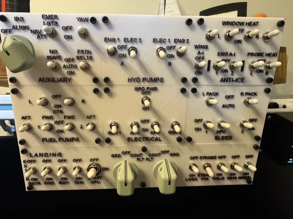
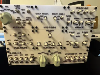
The front panels “HYD PUMPS” and “ELECTRICAL” should be mounted the same as the pictures, as they are the center panels and slightly smaller in width than the outer panels. I tried to correspond the location of the switches to the left/center/right side that they appear on the real plane's overhead. Obviously, due to this compact design, some switches may not appear in the exact location as the real plane.
General Assembly Instructions
- Insert your switches in each panel and tighten down the lock nut for each of them.
- Wire and solder your grounds together between the switches. Leave a single ground pigtail coming off one switch on each panel. This will minimize the amount of ground wire you need to connect to the ground terminals on the breakout module.
- Wire and solder a single positive pigtail to each of your switches. For the rotaries, you'll need to ensure they are being mounted with 4 inputs, and then wire each input according to the positions of the rotary that's in use.
- After wiring, mount each panel to the front of the enclosure using heat set inserts and hex screws.
- Strip a small amount of insulation off the end of each pigtail and begin wiring them to the Arduino breakout module. Only pins 2-52 and A0-A15 can be used. Don't forget to connect your ground wires to the GRD slots.
- Mount your Arduino to the rear panel using heat set inserts and hex screws.
- Mount the USB-C to USB-A panel mount to the rear panel. Connect the USB-A to USB-B wire between the rear panel USB and the Arduino.
- Insert the breakout module to your Arduino. Close up the back of the box and connect it to your computer.
- Install and open MobiFlight on your computer and initialize the Arduino (if you haven't already).
MobiFlight Profile
The final step in the process is to install MobiFlight, setup all the switch inputs and start flying! If you'd like, you can use my 737-800 profile here, but you will likely need to configure each input and change the pin number that corresponds to the pin you wired each of your switches to.
Disclaimer: I am not sponsored or endorsed by any of the above links/vendors/businesses. These are simply the products I used for my own switch box that worked for me.
License



Comment & Rating (19)