


Print Profile(1)

Bill of Materials


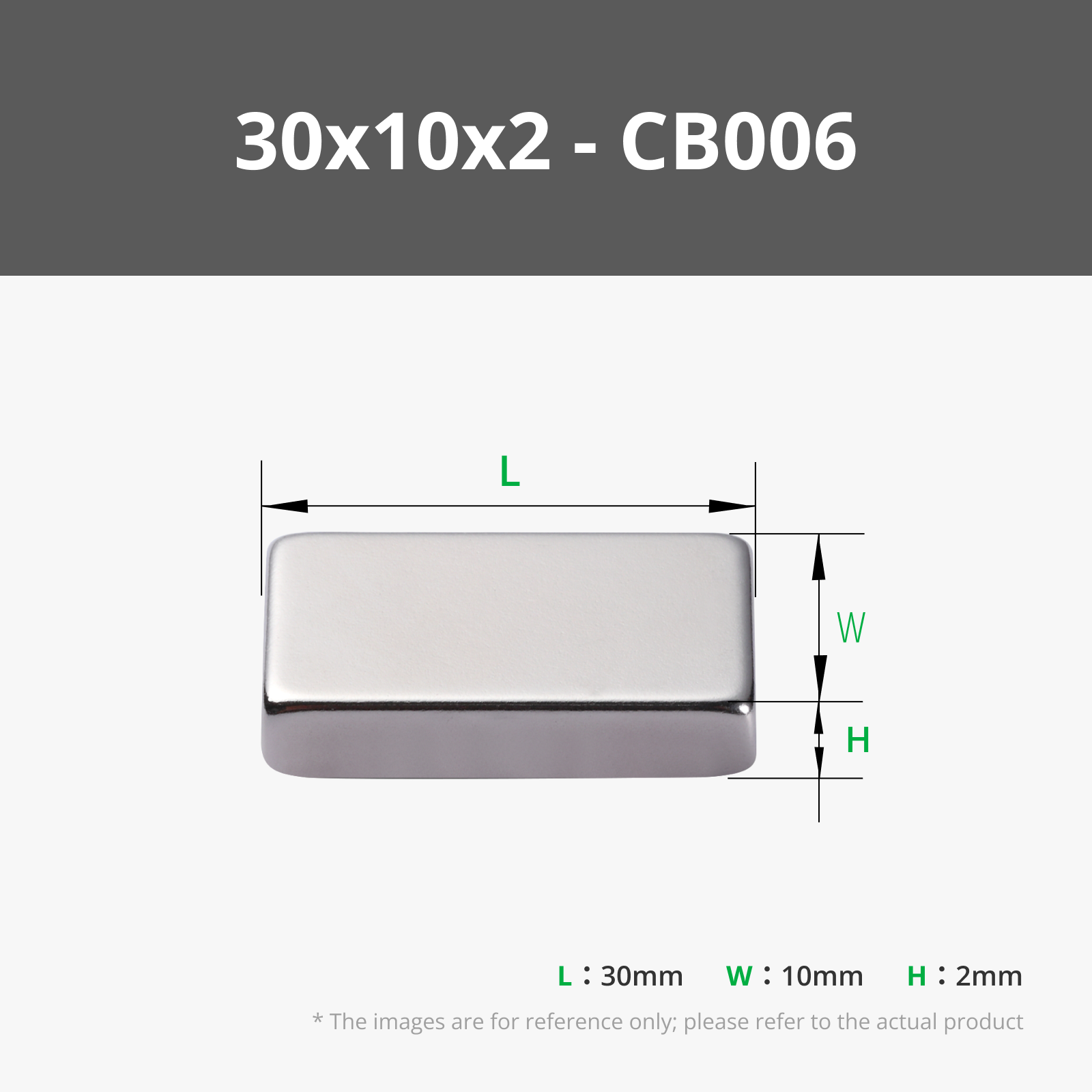


- Supportive Footpad - A1 x 2: https://eu.store.bambulab.com/collections/spare-parts-for-a1-series/products/supportive-footpad-a1-1
- Super Glue x 1:
Description
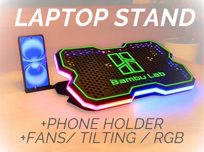
Boost Me (for free)
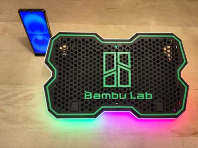
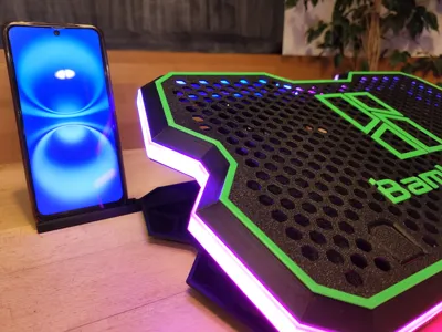
Print yourself an RGB laptop holder with fans and share your experience with us!
fully doable with bambulab's maker supply items
find the christmas edition here https://makerworld.com/en/models/883712#profileId-838361
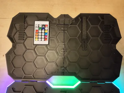
BUILD GUIDE (SEE PICTURES BELOW) :
NOTE: of you have 2 usb ports close to each other from one side of the pc (less than 1 cm space) then make a hole from the other side of the big surface with fan holes as well as the white led path creating a second path for the usb cable out of the model from the right) (i will update the model in a Version-2)
1) JOINING PARTS
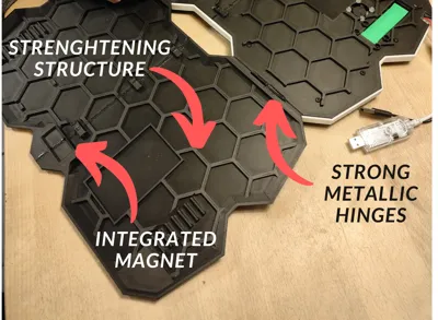
1- glue the HALVES together for a sturdy build and screw the layers together (with no glue for demontability)
2- the top logo needs careful gluing (using tape for allignment is advised)
3- screw in the 4 fans with M3 bolts so the fans face downwords (WITH THE SILVER STICKER FACING UPWARDS to the hexagonal mesh) (remove the silver sticker from the back)
4- insert the metallic hinges and glue one side in place
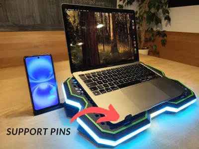
5- screw in the 2 stand rotating legs with M3 screws
2) WIRING
1- the wire management box is the 27cm long box
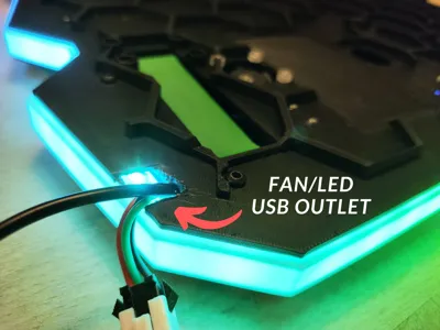
2- leave 20cm of USB cables out of the Stand (13cm for the led usb cable) then pass the wires and LEDs in the cable management box over the second layer
3- all the wiring will be made before screwing the frame
4- the usb cables enter the body of the stand from its left and right side ( and will be later fixed in place with the LED path over it kind of squishing the cables )
5- the cables then enter the cable management box
6- the led lights go straight to the back side and to the LED white path
and the fans cables get connected into the 4 pin connector
7- the OUT pin of the first 4 pin connector gets connected to the IN pin of the second 4 pin connector (for extra length)
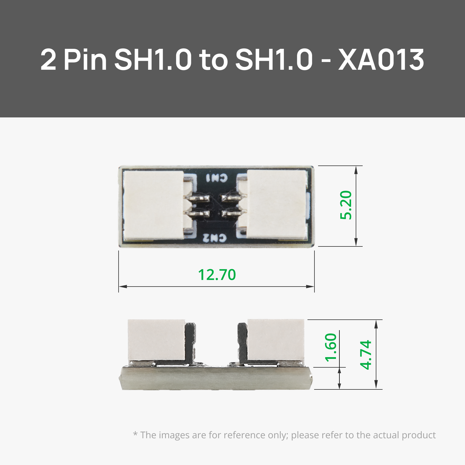
8- 2 fans will be connected inthe connection hub and then the cables exit the cable management box to the fans (attatch the SH1.0 to SH1.0 Connector to the side fans to extend their cable length)
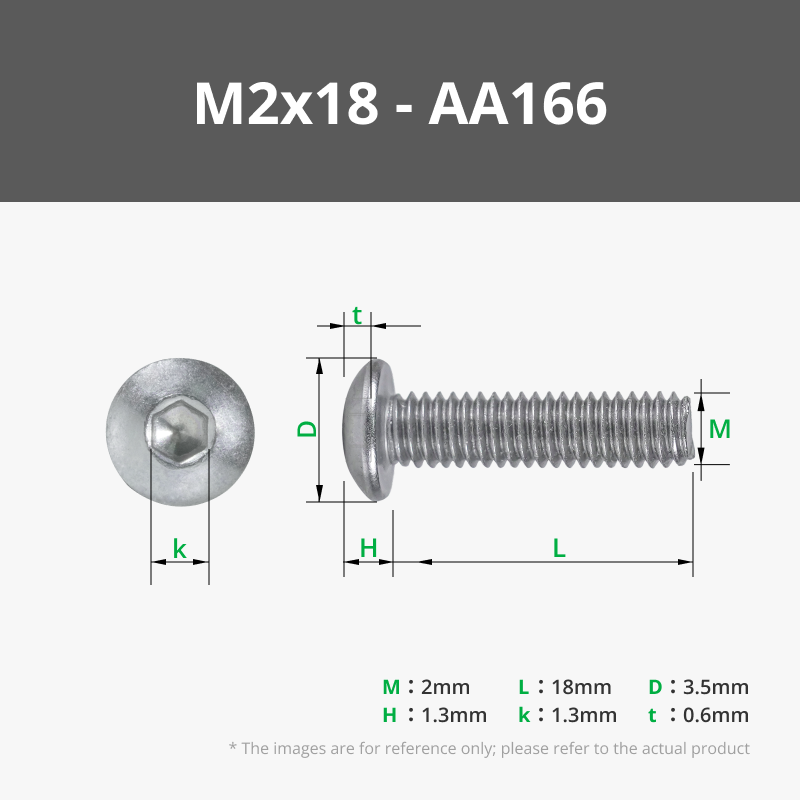
9- screw the wire management box with M2 screws
10- insert the LED in the white path in the small 2mm channel (super glue application is optional) (be careful when removing the LED path's supports)
3) ASSEMBLY
all the frame layers are screwed together with M3 screws


License
You shall not share, sub-license, sell, rent, host, transfer, or distribute in any way the digital or 3D printed versions of this object, nor any other derivative work of this object in its digital or physical format (including - but not limited to - remixes of this object, and hosting on other digital platforms). The objects may not be used without permission in any way whatsoever in which you charge money, or collect fees.
Comment & Rating (27)