Radio Panel Flight Simulator


Print Profile(1)

Description
This is a simple radio panel to use with your flight simulator.
I use this every time i'm doing an online flight on Vatsim (https://vatsim.net/) and it reduces my workload (switch between the views etc.) a lot.
Aside from that it gives me a more realistic feeling even if this is just a small piece of a cockpit.
The font and the used colours fit to Airbus cockpits.
Function:
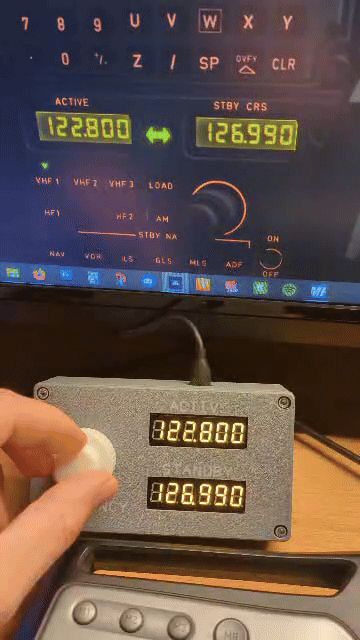
There are two 6-digit displays that display the active (transponding) and the standby frequency.
With the 2 rotary knobs you can adjust the MHz and kHz of the standby frequency.
The button of the rotary knob is used to switch between the active and standby frequency.
Whats needed in addition to the printed parts:
- 1x Arduino Nano (i used one version with micro USB)
- 1x Shield for Arduino Nano
- 2x 6-Digit display TM1637 (i used the version with yellow digits)
- 1x Dual axis rotary encoder with button
- 1x Small piece of PCB to solder the encoder onto (30mm x 30mm)
- Some cables
- Some ferrules
- Soldering iron
- 4x M3 x 5 (cover to housing)
- 2x M3 x 5 (shield to housing)
- 8x M2,5 x 5 (displays to cover)
- 2x M2,5 x 5 (PCB to cover)
- 2x 4-pin header 90° (connectors for displays)
To use it with your flight sim you need a software that connects the hardware to the sim.
For this i use Mobiflight which can be downloaded and used for free from the following website:
https://www.mobiflight.com/en/index.html
Maybe you can leave a donation to a appreciate the work of the guy(s)!
How to print:
For printing i used white and grey PLA to fit the colours of the Airbus cockpits.
The rest is just standard aside from the speed of the first layer.
Since the small letters are placed on the printing bed and printed prior to the housing itself, i slowed down the first layer so that the letters will stick better to the printing bed. With the standard speeds i got some problems and the letters fell of.
The rest is standard.
How to assemble:
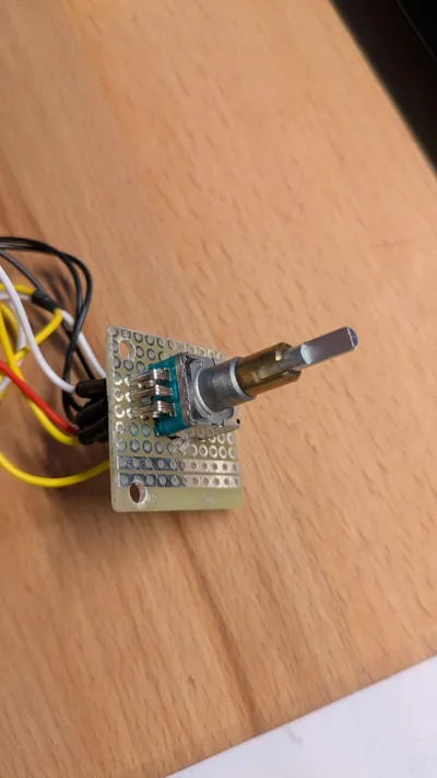
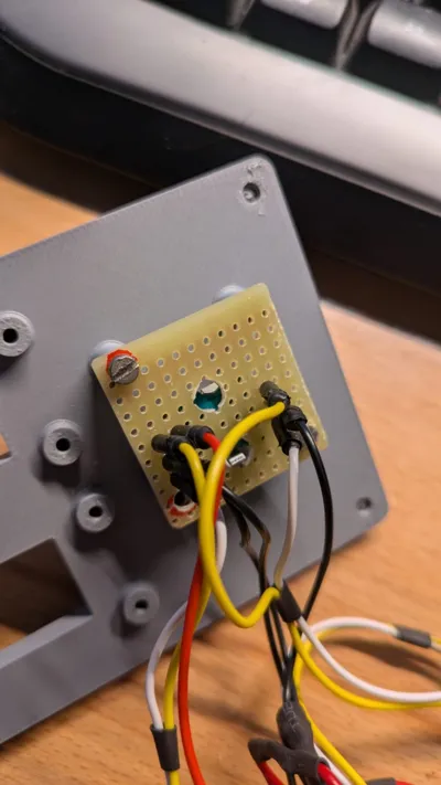
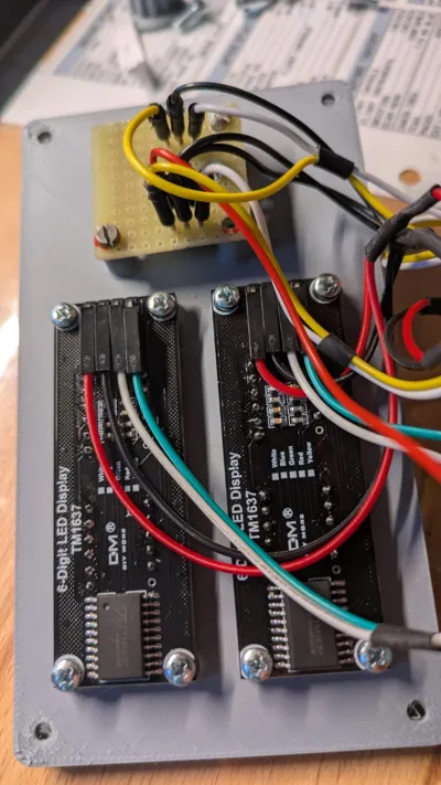
To assemble this panel you have to cut out a small piece of PCB, drill some holes into it (see picture), place the rotary encoder onto and solder it to the cables (see wiring diagram).
For a smaller space consumption i used 90° pin headers on the displays which also have to be soldered to them.
Then mount the displays and the PCB with the encoder to the cover as well as the shield to the housing with the given screws.
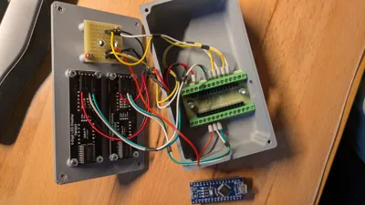
Start with the wiring of all components to the shield according to the diagram.
Now you can add the Arduino Nano to the shield and set up your software (e.g. Mobiflight).
When everything works as intended, mount the cover to the housing and have fun.
License
You shall not share, sub-license, sell, rent, host, transfer, or distribute in any way the digital or 3D printed versions of this object, nor any other derivative work of this object in its digital or physical format (including - but not limited to - remixes of this object, and hosting on other digital platforms). The objects may not be used without permission in any way whatsoever in which you charge money, or collect fees.
Comment & Rating (9)