Search models, users, collections, and posts

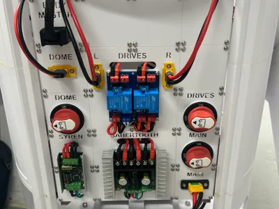
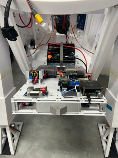
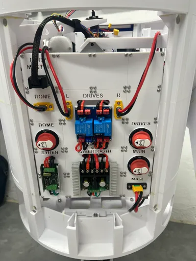
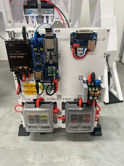
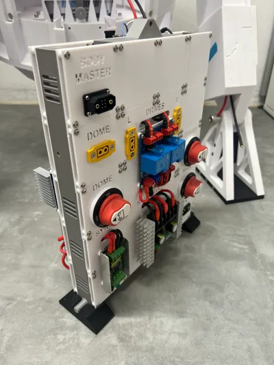
R2D2 Modular control unit (MCU)

Print Profile(1)

All
X1 Carbon
P1S
X1
P1P
H2D
X1E
H2D Pro
H2S
P2S
H2C
X2D
A2L

0.2mm layer, 4 walls, 40% infill
Designer
32.4 h
36 plates
5.0(26)

Open in Bambu Studio
Boost
157
307
124
88
502
237
Released 

Description

The latest version of the documentation is also attached where the assembly is described and also a list of needed parts!

General motivation

  • There are many good solutions for organizing all the control electronics for the whole selection of R2D2 bodys.
  • However, none of these solutions fully met my requirements, so I designed my own interpretation of a modular control unit the brain.

Requirements

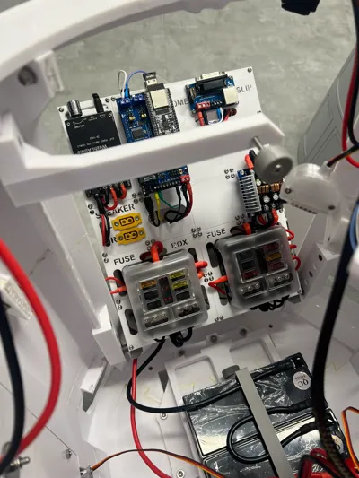
  • The module must be completely removable as a single unit to allow work on it at the workbench.
    • Everything must be possible without any special tools, i.e., plug-and-play instead of screws (almost achieved)!
  • To allow access when installed, the entire unit must be hinged (no tools required for this step).
  • The design must be modular, allowing it to be adapted to specific requirements.
  • The design must be based on a grid (60x60mm) and offers panels ranging from 1x1 to 1xX.

Used Mods & Kudos

Note: The following list contains an overview of the mods that I currently use in my Droid. It is not mandatory to use them as well, but I can confirm that they are compatible with each other.


Documentation (2)

Assembly Guide (1)
Documentation.pdf
Other Files (1)
README.pdf

Comment & Rating (124)

(0/1000)

Boosted
This is absolutely wonderful, used the majority of your design but also added a few custom panels of my own. Absolutely brilliant. Currently mine is about 90% done.
The designer has replied
designer
1
Reply
This is looking awesome 👍 Thank you for sharing. Feel free to Upload your panels as a remix 🤗
1
Reply
Boosted
Replying to @Buddinski88 :
Uploaded them as a remix + my version of the body adapters since I don't have the luxury of a backdoor 🤦‍♂️ This allows me to easily remove the panel.
(Edited)
designer
2
Reply
Thanks for putting this together.
(Edited)
The designer has replied
1
Reply
Thank you for you comment :-) Have fun with the MCU!
0
Reply
Boosted
@Buddinski88 Quick question, is this a printed housing for the MPX JX6 connector? The male/female set from Ali Express have very little protection for the wires and make it hard to unplug without damaging the soldering.
(Edited)
The designer has replied
designer
1
Reply
Hi, I’m not sure what’s happened but I cannot for the life of me find anything like this pictured part. I have printed everything but nothing looks like this. what is it called and what plate number is it on? Thanks
The designer has replied
0
Reply
Hi @kaybee69 this is no printable part. Only for reference of the Body ☺️
0
Reply
Do you have or know a way to connect this to a com 8 alumminum frame?
The designer has replied
0
Reply
unfortunally not.
0
Reply
Replying to @Buddinski88 :
Ok ill make one, and link your build into it so more can use it
designer
1
Reply
Replying to @user_1907393859 :
Awesome 👍🏻
0
Reply
Print Profile
0.2mm layer, 4 walls, 40% infill
this is an amazing project for your R2. love this thing.
The profile uploader has replied
0
Reply
@BassPlayinFatty thank you very much! :-)
0
Reply
Is this design compatible with the v2 body ?
The designer has replied
0
Reply
Sorry but i Can’t say that. Your can Print the left an right Body Adapter and Test it from there.
0
Reply
Replying to @Buddinski88 :
No worries. If I go ahead with this design, I'll design my own adapter. Hopefully I can do this in Fusion 360 (hobbyist license)
designer
1
Reply
Replying to @ntsarb :
@ntsarb any luck with an adapter for a V2 body? I'm about to embark on printing this masterpiece but thought I'd check to see if I need to change anything first...
0
Reply
Great design! I had created my own single print electronic board, but this is much better. Thanks for putting this together. As a note, in your documentation, in Preparation of the Body Adapters, you mention using two M3x18 mm countersunk screws. I believe those should be M4x18 to go with the M4 threaded inserts. Same with the required parts above that.
The designer has replied
designer
1
Reply
Thanks for the kind words and for pointing out the mistake! :-) I have just corrected it in the documentation.
0
Reply
Replying to @Buddinski88 :
Couple more issue I found. The holes for the pins on the Frame connectors are offset by a couple mm. However you only have 1 version of the stand included. There should also be a mirrored version of one of the stands, instead of the same one x2. Otherwise it doesn't fit. Next, on both body adapters. The holes don't have a bevel to allow for countersunk screws, so they do stick out a bit. Although they don't really get in the way. thanks again!
0
Reply
Replying to @SpaceCadet :
@SpaceCadet Thanks for the tip. I forgot to update the print profile since November. I have just updated it and now both problems should be fixed. Please download the data again and sorry for the inconvenience :-)
0
Reply
Is it possible to include the dimensions (distances between screw-holes) for each type of module in the documentation? I have already purchased most of the required components but not necessarily the same as here, so I need to check which modules can be re-used and which ones I need to design for my parts. I like the design and I need to check whether I can fit all my components. For example, besides the standard ones, I have a Jetson Xavier AGX for ROS2-based robotic functions, a GPS receiver with integrated antenna, LORA for communication, etc. I'm building it as an educational and experimental platform, to try out a wide range of technologies.
(Edited)
The designer has replied
designer
1
Reply
That is indeed a possibility, but would be significantly easier if I had a paid Fusion360 license. This will take some time, but I have added it to my list. Maybe you could give me the names of the STL files you are particularly interested in? Anyway, your project sounds very interesting. Are you planning something with Longrange, if I'm interpreting Lora correctly?
0
Reply
Replying to @Buddinski88 :
I have the components and the relevant dimensions (size, screw hole locations), e.g. from the NVIDIA Jetson Xavier AGX embedded computer, the Polulu servo controller, etc. For small devices, it may be possible to fit two PCBs on the same tile. For others, larger tiles (x*60) will be needed. Regarding LORA, I'm thinking of using it as a backup channel, i.e. where no WiFi/Mobile connection is available.
(Edited)
designer
1
Reply
Boosted
A standard squares in the frame seems to be 53mm wide x 52mm high. I took that from measuring the printed frame with cheap calipers ;-) Use with caution but it should be ok.
0
Reply
I'm having an issue with the side rails. The holes on the rails are far too big to heat set a 3M into. The diameter is closer to a 5M inset....but a 5mm screw won't fit through the rails. So, am I miunderstanding the instructions?
The designer has replied
0
Reply
Hi, in the documentation you can read that M4 inserts has to be used and not M3 inserts.
0
Reply
Replying to @Buddinski88 :
I tried multiple M4 too, holes are still too big. A lot of guys in the facebook group have said the same thing and said they found a work around with some 3M inserts off Amazon, so I bought them. They arrive today, I'll report back.
0
Reply
Replying to @user_2196308311 :
HI What inserts did you end up using for the frames? I have just found the same thing that the M3 inserts are too small for the frames.
0
Reply