V4 OpenHornet mod for Winwing integration


Print Profile(1)
Description
OpenHornet modification for WinCtrl (Winwing) integration V4
Summary
This is for home cockpit builders who are building an F/A-18 cockpit using OpenHornet plans or similar. This model provides modifications to the original OpenHornet plans that allow you to integrate the WinCtrl / Winwing MIP into the OpenHornet upper and lower instrument panel (UIP and LIP). It is aimed at builders who intend to do a full WinCtrl / Winwing MIP integration, including HUD panel. The parts provided herein are designed with 3D printability in mind. Only the main face plate is recommended to be cut from acrylic rather than printed, due to size.
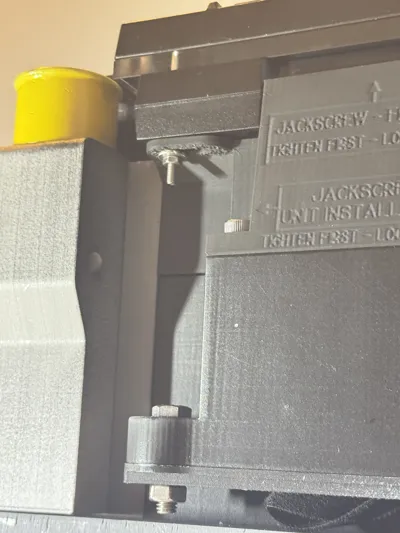
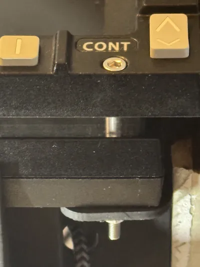
Update Mar 2026: Updated one part (WW MFD LOWER SUPPORT). This update improves the rigidity of the left and right MFD. Two additional screw mounts were added. By using M3x50mm screws, it is now possible to fix the lower part of the MFDs against the bracket, resulting in much improved rigidity. See new photos for details. Print with support is needed for these!
Update Jan 2026: Added left and right glareshield files that include small cutouts and blisters for the corners of the Winwing displays
Update Oct 2025 V2→V3: new and improved AMPCD holder. Three improvements: (1) a more “snug” fit to the HUD panel; (2) a big storage box behind the AMPCD which allows you to store kneeboard, keyboard and other stuff at a quick access location (3) improved construction design now allows full disassembly from the front - no crawling into the LIP to unfasten some screws anymore. Detailed description below.

How to use this model
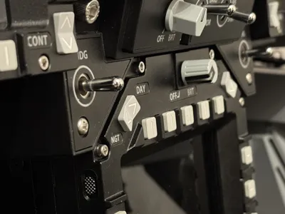
Use this model to build your pit using the basic OpenHornet upper instrument control panel (UIP) frame, but integrate your Winwing MIP components into the build. You will replace the following visible parts: Left DDI, right DDI, UFC, HUD control panel and AMPCD. To achieve this, this mod provides the files for a modified face plate (acrylic) and modified brackets (3D printed).
Feature overview
The integration positions the Winwing UFC and HUD panels as closely as possible to the OH-specified position:

Due to the Winwing MFD screen encasings, the face plate can't use six screws on the outboard longeron. However, the assembly provides new / alternative securing. The main holding bracket is firmly secured using M5 screws and six heat inserts:

The lower central brackets are modified to support and secure the main holding bracket:

The BIT box is open on the lower side, providing (some) access to the extra buttons on the Winwing UFC:

The back cover of the UFC panel has chamfers to make space for the eyebrow panels:

New feature Oct 2025: As of V3, the improved AMPCD mount ensures a snug fit with the UIP. The AMPCD is still removable without removing the UIP. Construction has been redesigned to allow full disassembly from the front - no more hidden screws. Below / behind the AMPCD, a large storage box is implemented, which allows to store kneeboard, keyboard, mice, VR dongles etc. Depending on your printer size, dovetail cuts are needed for printing.


Photo of V3 prototype installation. You can see the dovetail cut between the gray and the black parts. BambuLab screenshot on how to accomplish this is below.


Character of this mod
To integrate the Winwing MIP into OpenHornet, several design choices have to be taken. This is due to the fact that the Winwing MFD bezels are larger and that the Winwing HUD panel comes with the HDG and CRS knobs directly attached to it. The existing solutions by the community follow different design choices. The following table provides an overview of this mod and the other Winwing integration mod by Nick, to help you decide which one to pick.
| Ulukaiis mod (this mod) | Nicks mod | |
| Idea | Reasonable effort integration w/ only 11 modified parts. No custom PCBs required | High effort integration with customized eyebrow panels. Requires custom PCBs |
| Resulting architecture | MFD screens extend further downwards by 1.5 cm compared to OH spec | MFD screens extend further upwards, EWI panels are reduced in size and custom design |
| MFD screens | Winwing | Winwing, encasing removed |
| UFC | Winwing | Winwing |
| EWIs | OpenHornet | Custom |
| HUD panel | Winwing | OpenHornet |
| HDG/CRS sel | Winwing | OpenHornet |
| AMPCD | Winwing | N/A |
Manufacturing parts list
Parts for the newly improved AMPCD integration are listed in bold.
| Part Number | Amount required | What is it | Replaced part in OpenHornet standard design |
|---|---|---|---|
| ACRL_OH1A1-12_MOD_A | 1 | Completely redesigned face plate (acrylic) | OH1A1-12 |
| FDM_OH1WW-01 | 1 | Main mounting plate between face plate and Winwing UFC and HUD panel | NEW |
| FDM_OH1WW-02 | 1 | Provides encasing for the Winwing UFC | NEW |
| FDM_OH1A8A4-10_MOD_A | 1 | Modified upper box (BIT box) for the UFC including the go/no-go lights | OH1A8A4 |
| FDM_OH1A8A4-10_MOD_A cablue guide | 1 | Separate cable guide for the cables to the green and yellow LEDs and the BIT test switch of the bit box. This part is separate to maintain easy 3D printability | NEW |
| FDM_OH2A3A1-10_MOD_A | 1 | Modified holder for the AMPCD without the HDG / CRS knobs and with positioning of the AMPCD harmonized with the UIP Winwing installation | OH2A3A1 |
| FDM_OH1A1-23 | 1 | Modified HUD panel aft support. Optional part (you do not need to mount it - it is just there for completeness reasons) | OH1A1-23 |
| FDM_OH1A1-19 | 2 | modified DDI panel lower support (you need to print two of them, one for the left side of the DDI and one for the right side of the DDI) | OH1A1-26 |
| FDM_OH1A1-22 | 2 | Modified version of the display pressure foot. Instead of pressing the display, it is now an additional fastening position for the face plate. | FDM_OH1A1-22 |
| FDM_OH2A1-17-MOD-A | 1 | Modified version of the Upper Central Pedestal Face of the LIP. It mounts the new AMPCD holder (FDM_OH2A3A1-10_MOD_A) | FDM_OH2A1-17 |
| FDM_OH2A1-17-MOD-B | 1 | Cover lid for the storage box of FDM_OH2A1-17-MOD-A | NEW |
| FDM_OH2A1-17-MOD-C | 1 | Mounting bracket for FDM_OH2A1-17-MOD-A | NEW |
| FDM_OH2A1-17-MOD-D | 1 | Mounting bracket for FDM_OH2A1-17-MOD-A | NEW |
| FDM_OH1A1_10_UIP_MOD_A LEFT GLARESHIELD | 1 | Replace the ABS glareshields. This version has a cutout and a blister for the upper outward corner of the Winwing DU. The original part is ABS, but most users print this part as standard FDM print in several parts | ABS_.125_OH1A1_10_UIP_MOD_A LEFT GLARESHIELD |
| FDM_OH1A1_29_UIP_MOD_A RIGHT GLARESHIELD | 1 | Replace the ABS glareshields. This version has a cutout and a blister for the upper outward corner of the Winwing DU. The original part is ABS, but most users print this part as standard FDM print in several parts | ABS_.125_OH1A1_29_UIP_MOD_A RIGHT GLARESHIELD |
Additional required COTS parts list
- Winwing MIP including three MFDs, three screens, UFC and HUD panel
- 4 M3 screws, 42mm. Exact Length depends on your face plate thickness.
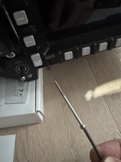
- 4 M3 screws, 50mm, to fasten MFD against lower support bracket (OH1A1-19 )
- 8 M3 hex nuts (usually included in your MIP)
- 6 M5 screws, 12mm, to fasten the UFC to the UFC mount (FDM_OH1WW-02)
- 6 M5 screws, 12mm, to fasten the UFC mount to the face plate (ACRL_OH1A1-12_MOD_A)
- 6 M5 heat inserts for the UFC mount
- 2 M5 screws, 12mm, to fasten the HUD BIT box (FDM_OH1A8A4-10) to the face plate
- 1 M5 screw , 30mm, to fasten the HUD BIT box (FDM_OH1A8A4-10) to the UFC box lower (OH1WW-02)
- 1 M5 heat insert, to fasten the HUD BIT box (FDM_OH1A8A4-10) to the UFC box lower (OH1WW-02)
- 6 M4 flat head screws, to fasten the face plate to the UIP structure
- 2 M2 PHS screws, M2, optional, as additional outboard fasteners for the face plate
- 11 heat inserts M4 for the AMPCD mount and bracket
- 4 M4 screws 15mm to fasten the AMPCD mount to the upper central pedestal face
- 1 M4 screw 30mm to fasten the AMPCD mount to the upper central pedestal face
- 4 M4 flat head screws 10mm to fasten the AMPCD winwing screen to the AMPCD mount
- 4 M5 screws, 20mm, to fasten the AMPCD to the AMPCD brackets
Additional required mechanical changes
1. To fit the Winwing DUs, you will need to perform small cutouts into the outboard UIP longerons. The exact size depends on the thickness of your material.
2. The same goes for the acrylic glareshield (the top cover of the UIP). You will need to provide some cutouts for these corners as well.


Use at your own risk. Thanks to Winwing and OpenHornet for their incredible foundational work. OH license applies. Have fun!
How to assemble
LIP:
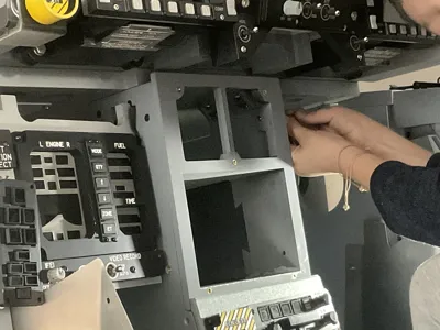
- Install the "Upper Central Pedestal Face Mounting Brackets" L / R to your structure. Each requires two heat inserts, don't forget them!
- Install the "Upper Central Pedestal Face + Box" to the structure by using the brackets
- Install the AMPCD mount
- Install the DisplayHoldingBrackets to the Display (not to the mount!)
- Attach the cables to the display
- Install the display onto the AMPCD mount. Four M4 flat head screws will hold the display holding brackets from the side
UIP:
- Prepare the UIP frame: remove the old face plate (if any) and install the modified OH1A1-25 (central bracket) and OH1A1-19 (WW MFD lower supports).
- Prepare the face plate: Assemble the whole MIP to the face plate, including left and right DDIs. You might want to connect the cables now
- Join the UIP frame and the face plate.
- Install the UFC box cover (OH1WW02) by sliding it in from above
- Install the UFC HUD Bit box and cover.

Comment & Rating (20)