
Arduino Robot Lawnmower - Robot tagliaerba Arduino


Print Profile(6)



Bill of Materials


Description
Model
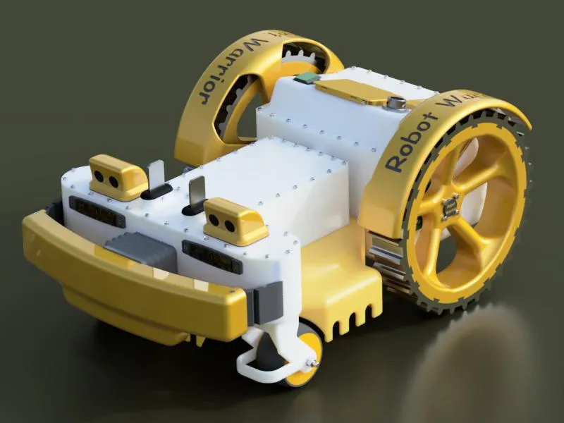
Here is my version of the Robot Lawnmower 4.0
This robot is controlled by an Arduino Mega that manages the robot's program and by an additional Arduino UNO that generates the signal for the perimeter wire
At this link you will find the codes for the various robot boards, the perimeter wire, and the libraries to make everything work
https://github.com/Marcobedendo78/Robot-Arduino-4.0
Here you will find the parts to print for the charging base
https://makerworld.com/it/models/432910#profileId-337517
Boost Me (for free)
Boost me if you like my Robot Lawnmower
Printed Parts
I printed the entire robot in ASA and ABS to be weather-resistant, but nothing prevents you from printing it with other materials
Some parts, such as the supports for the pivoting wheels and the cutting blade disc, are made of PETG-CF to be more resistant to the stresses they must withstand
Then there are the wheel hubs and the articulated shaft that makes the robot jointed, which I made of stainless steel to prevent any possible breakage While I made the piece connecting the cutting deck to the motor from aluminum to be both robust and lightweight
P.S.: The ASA parts are the three frame parts and the covers, while all orange parts are ABS The wheel treads are then made of TPU so that if they wear out, they are easily replaceable, as are the front bumper bellows and the two side joints
Subsequently, there are two parts of the front shell that must be glued together to make it a single, airtight unit, like the top cover
Video of the robot in operation
Parts to insert
In the various robot parts, there are several blind holes where M3-M4-M5 threaded brass inserts must be placed so that screws can be tightened without stripping the plastic
Stainless Steel Screws
For most, I used M3x10 recessed hex screws
For the wheel hubs M4x20
Motor mounting on supports M4x12
Mounting of six motor supports M5x12
Main shaft mounting M6x10
Cutting blade plate mounting M6x20
Front shell mounting to central M5x12
Fork mounting in central shell M4x10 flat head
Wheel mounting on pivoting supports M6x70
Pivoting support mounting collar screws M10x30
Pulley and joint mounting collar screws M5x30
Bearings
Bearings 626zz 8 Pcs
Bearings 6001zz 4 Pcs
Bearings 6004zz 2 Pcs
Electronic Parts
Arduino Mega 2560 R3 1 Pc
Arduino Nano 1 Pc
NodeMCU esp6266 1 Pc
LM386 power amplifier board 1 Pc
5A ACS712 current sensor 2 Pcs
Voltage sensor 1 Pc
Water level sensor 1 Pc
1-channel 5V relay module
HD44780 16x2 Display Module with I2C interface 1 Pc
LM2596 DC-DC buck step-down converter 2 Pcs
300W step-down converter 1 Pc
DS1302 clock 1 Pc
HC-SR04 ultrasonic sensors 2 Pcs
Gy-271 3-axis magnetometer sensor HMC5883L digital compass (avoid those with QMC 5883 sensor) 1 Pc
BTS7960 43A wheel and blade motor drivers 3 Pcs
Ø16 flat head waterproof stainless steel buttons 4 Pcs
Gebildet 12/24V waterproof rocker switch with LED 1 Pc
1V 6 universal LED side marker lights 2 Pcs
5x5x1 Neodymium magnet 1 Pc
Compression spring Ø20 wire 1.2 height 30 mm 1 Pc
NO magnetic Reed sensors 2 Pcs
150mH Inductor 1 Pc
Battery
BMS 4s 30A 1 Pc
Battery 4s 14.8v 80c 6200mah 2 Pcs
Active balancer 4s 5A
Motors
For drive wheels:
Micromotors E192 12Vdc 22/20 rpm Geared 180:1 Motor 2 Pcs
https://www.cselettronica.net/default.asp?cmd=getProd&cmdID=20156
For cutting blade:
12V 30W permanent magnet motor with threaded shaft 1 Pc
https://www.amazon.it/dp/B076M53HC9?ref=ppx_yo2ov_dt_b_fed_asin_title&th=1
Cutting blade plates
1 pack https://www.amazon.it/dp/B08YRRN1FG?ref=ppx_yo2ov_dt_b_fed_asin_title&th=1
Tips
I recommend making the wheel hubs and the articulated shaft that makes the robot jointed from stainless steel I do not guarantee durability if made of plastic I made them from stainless steel While the cutting disc support, if not aluminum, should be made of a reinforced material at most In plate N°18 I have included the printable versions
I have also added the drawings for the stainless steel parts
Free Project:
This robot is a completely free project in which I have invested a lot of time and effort I don't charge anything for it, wanting to share it with other technology and robotics enthusiasts
It's free, but if you feel the need to support me, you can offer me any amount you wish Thank you
https://www.paypal.com/pool/9blLX2JvUL?sr=wccr
Update
Uploaded the print profile for the side fenders with lettering and the rear shell For those who do not want to reprint the rear shell, it is possible to drill 6 Ø4 holes using the fender resting on the motor support and mount 6 M4x20 stainless steel screws with corresponding washers and self-locking nuts (there are 3 holes per fender) Whereas if you print the shell, 6 M4x10 stainless steel screws with corresponding washers and 6 threaded inserts to be placed in the holes are sufficient Having already printed everything, I preferred to drill the holes
Update
Uploaded the print profile for the parts that make up the cutting blade guard, 2 cm shorter I have varied the height so that the guard is flush with the grass and not submerged in it This way, if you have a lawn that is not perfectly flat, the robot will not encounter obstacles when maneuvering and will still keep the blade well protected
Update
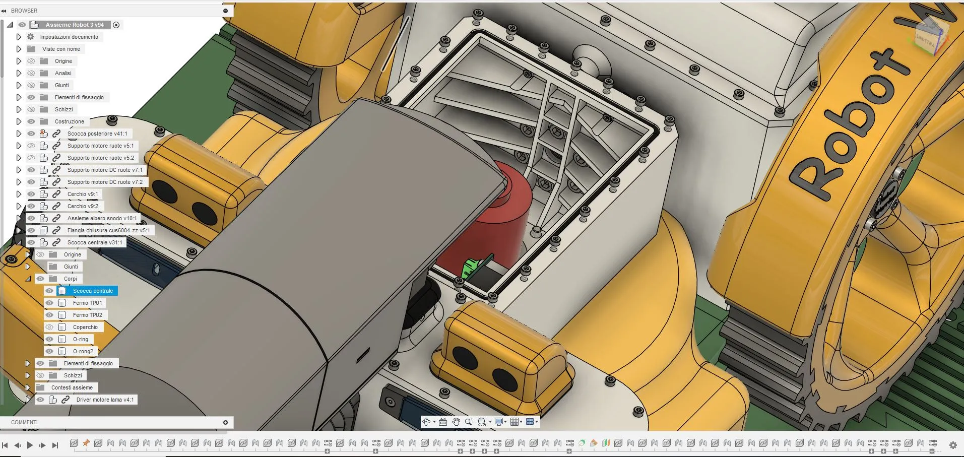
After a fair bit of use, I am forced to replace the central part of the robot due to breakage at the point where the articulated shaft is screwed in It might be because I only created 3 loops for the walls during printing or because the ribs were too short, but it broke So I modified the ribs by extending and increasing the horizontal ones and added two vertical ones in the central shell Now I have printed the new part in ABS-GF and not ASA-GF because Bambu Lab does not have it and because printing solid walls results in too much material deformation during printing
Update
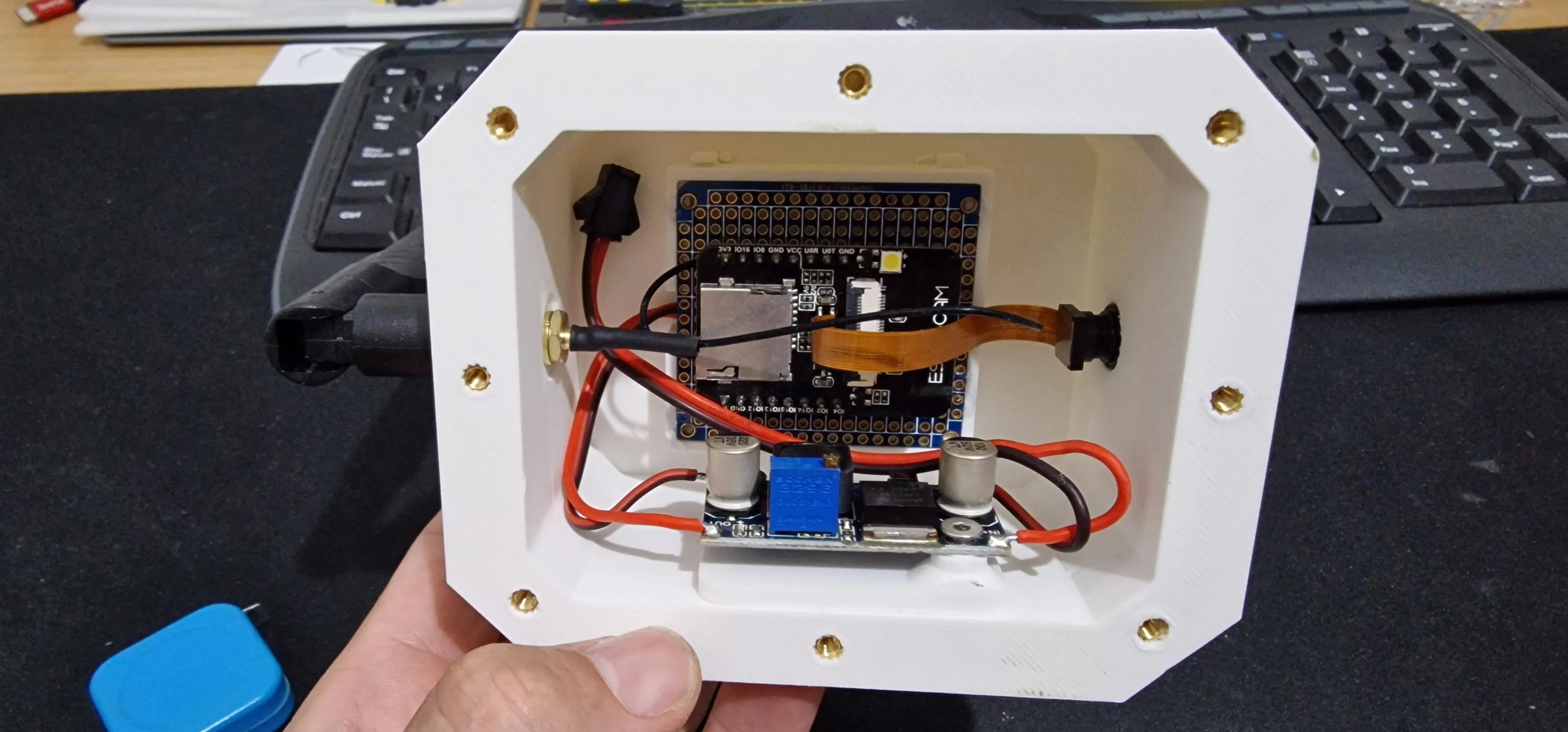
Uploaded the print profile for the parts to install an ESP32-CAM module to be implemented on Home Assistant to see what the robot is doing The modification consists of 3 parts:
New central shell cover, camera shell, and sealing gasket
For the modification, you need:
1 Pc ESP32-CAM with antenna
1 Pc Wide-angle lens with long flat cable
1 Pc ElectroCookie breakable PCB, Board with Power Rails for Arduino and Electronics, Gold-Plated Strip, 3.8 "x3.5
2 Pcs 2.54 pitch Pin Header
1 Pc LM2596 DC-DC buck step-down converter
I printed a support for the converter and then glued it inside the camera housing
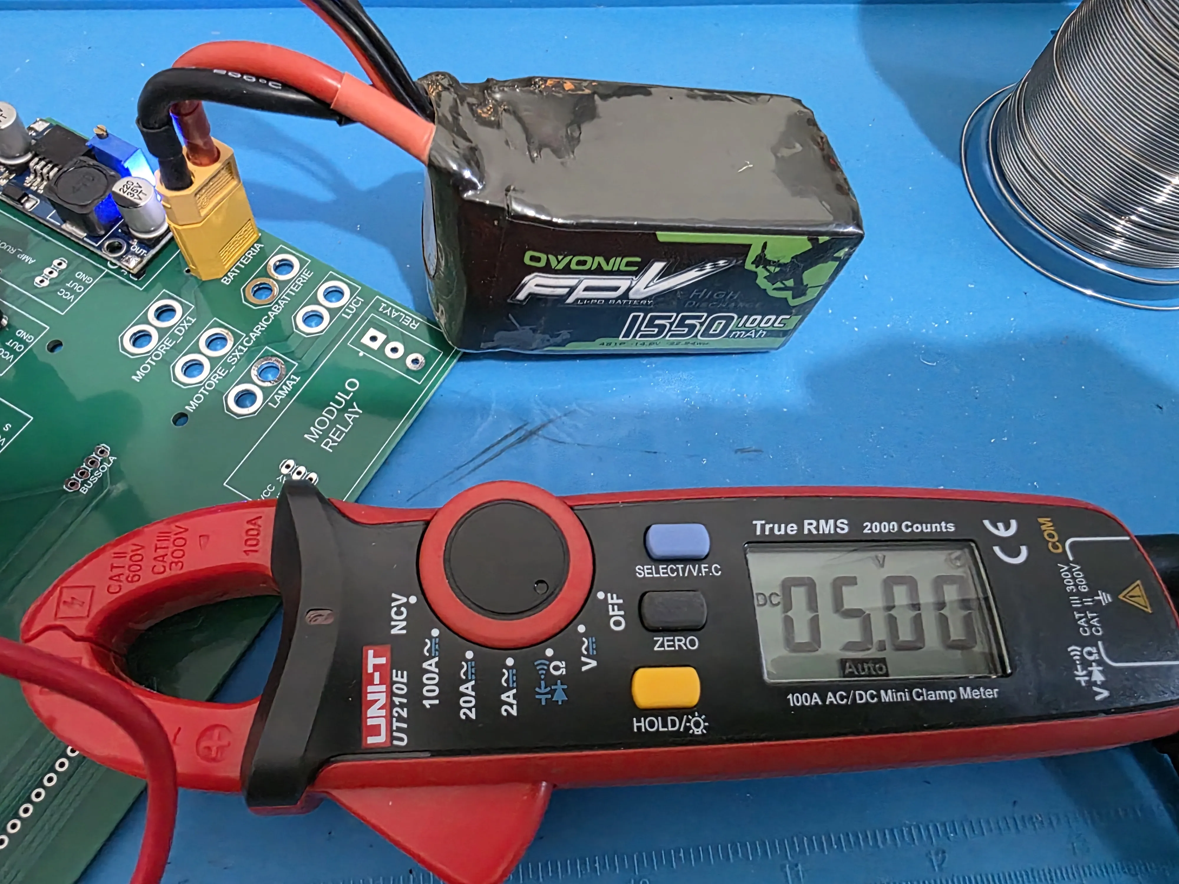
To power everything, I took power from the battery and routed it to the LM2596 DC-DC step-down converter, which must be regulated to 5V output The LM2596 DC-DC step-down converter must be adjusted before inserting the ESP32-CAM
Update
Re-uploaded the main print profile with a modification to plate N°8, replaced the old motor supports because the motor holes were too small and therefore incorrect Micromotors motors require M4 screws, not M3 The problem can be solved by enlarging the 3 holes and their countersinks if you want to reuse the old ones If similar motors from other brands are used, I do not guarantee that the hole sizes will be correct
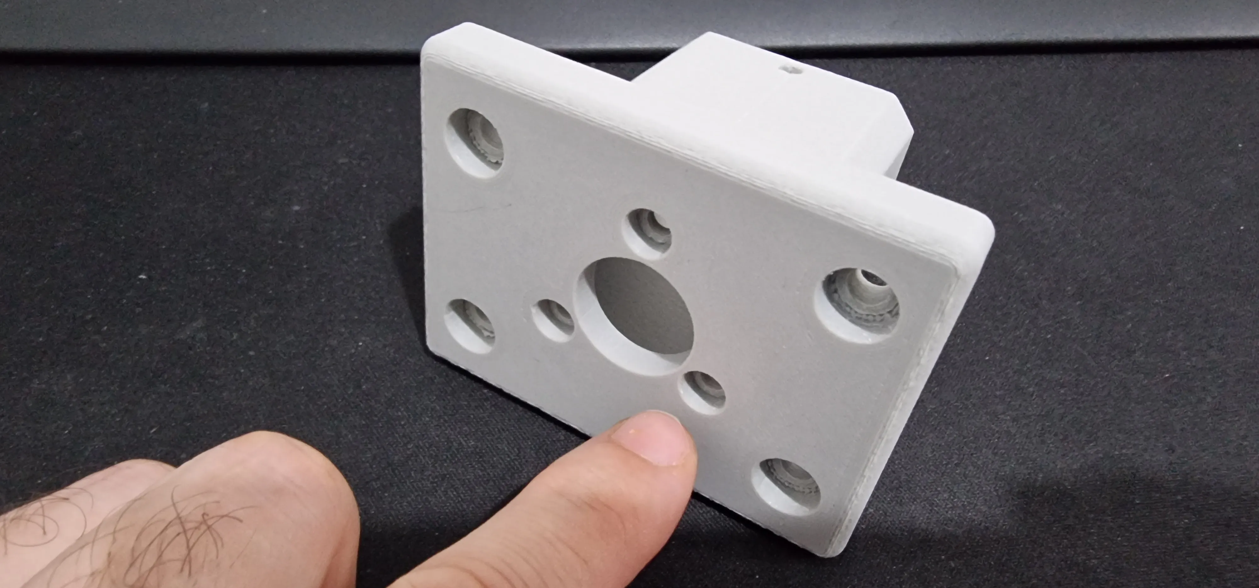
Update
Uploaded the print profile for the parts to install single-sensor ultrasonic modules These are suitable for outdoor use and are waterproof Of course, before inserting them into the hole, just apply a bead of silicone and then insert the sensors into place
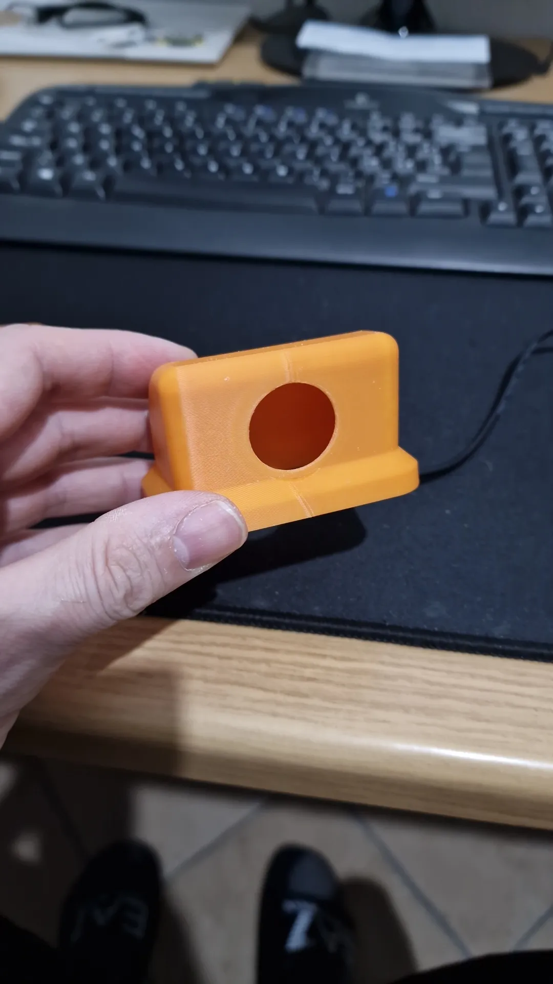
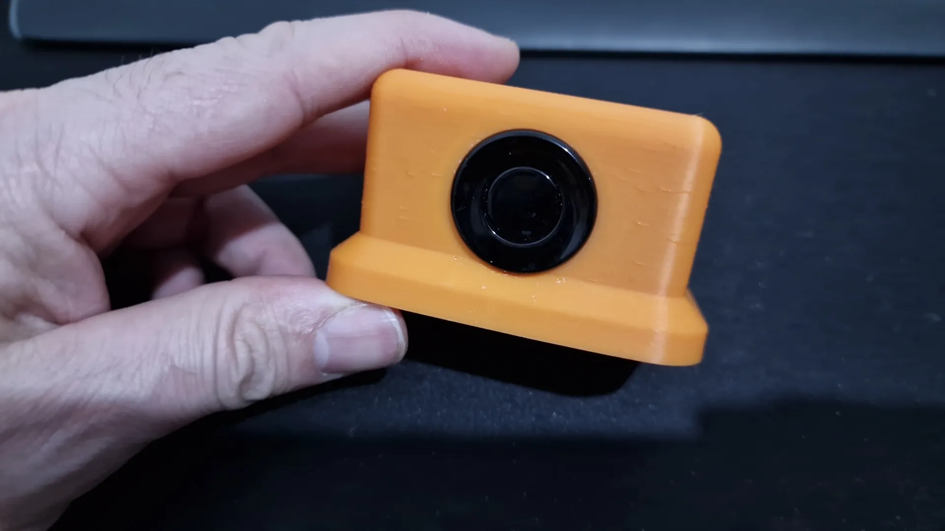
Subsequently, if you want to insert the board into its housing below
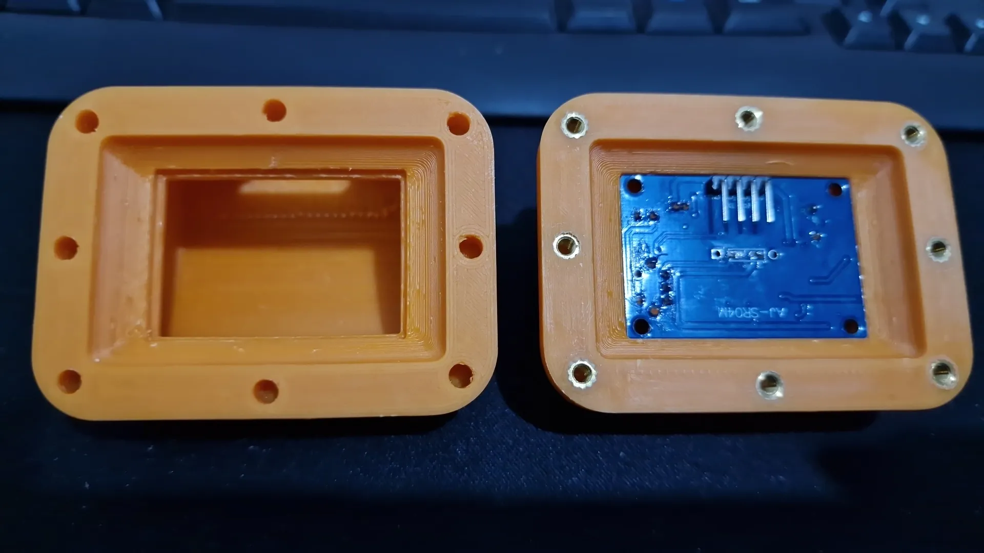
you need to shorten the cable and solder it directly onto the board, removing the connector and moving the 4 pins 90° to the opposite side and facing the center of the board The board slot is slightly narrower than the board because this way, with a light sanding and chamfering of its corners, it fits snugly This is intentional because not all boards have the exact same precise measurement to the tenth, and doing it this way avoids fitting issues
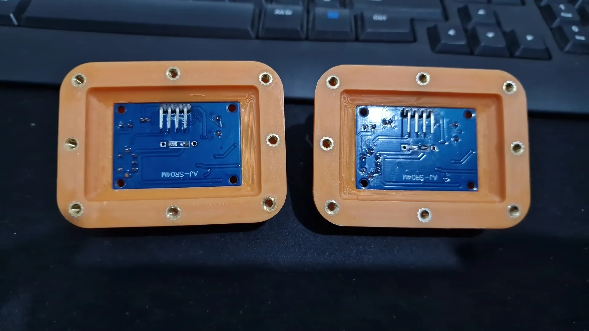
For the modification, no changes to the sketch are needed; the important thing is to respect the connection pinout (check with the old model, even if it is the same)
For the modification, you need:
2 Pcs Ultrasonic sensor covers
16 Pcs M3 threaded brass inserts
2 Pcs JSN-SR04T ultrasonic measurement module
1 Pc 90° 2.54 pitch Pin Header (if existing ones are not reused)
Update
Uploaded the print profile with all updated parts and their corresponding updated print profiles for various materials The only plate to be printed 8 times instead of just once is N°22, which contains the TPU 95A traction wheel tread I have also uploaded the list of spools needed to print the robot Those who don't want to use ASA can use ABS
Update
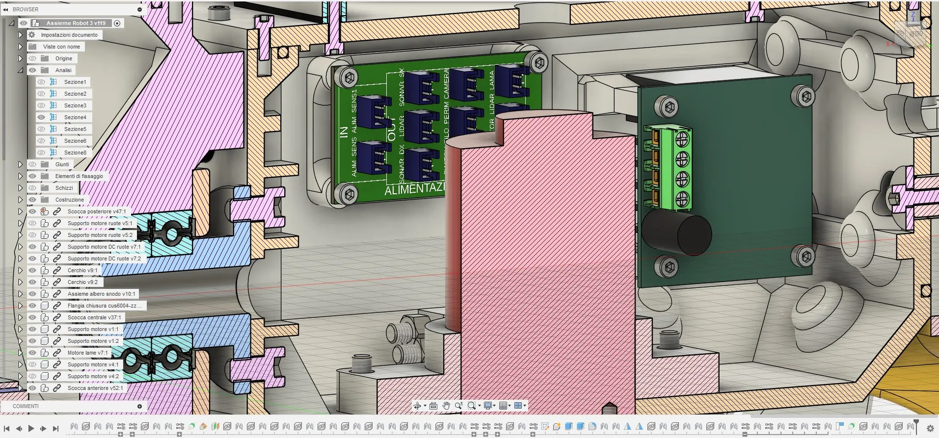
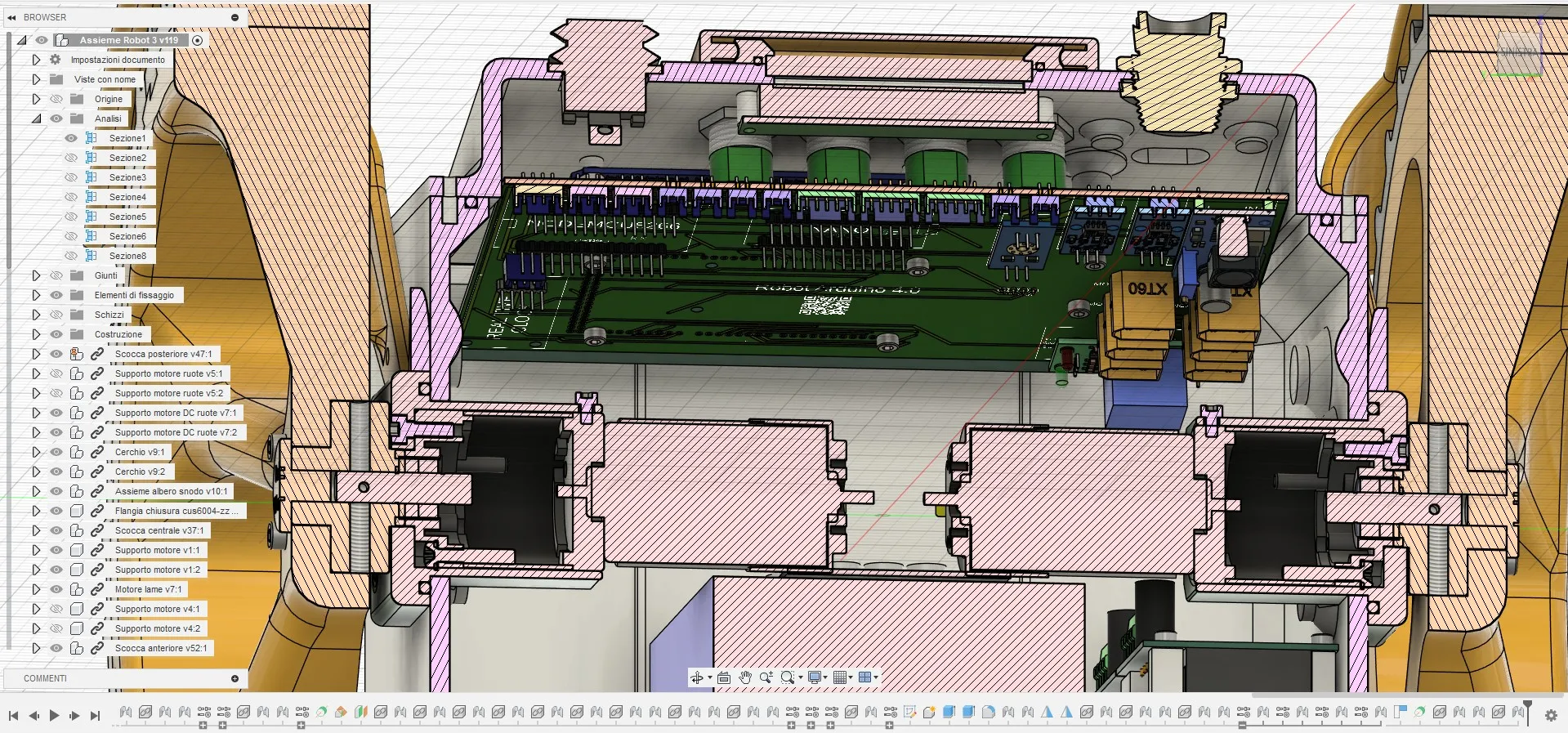
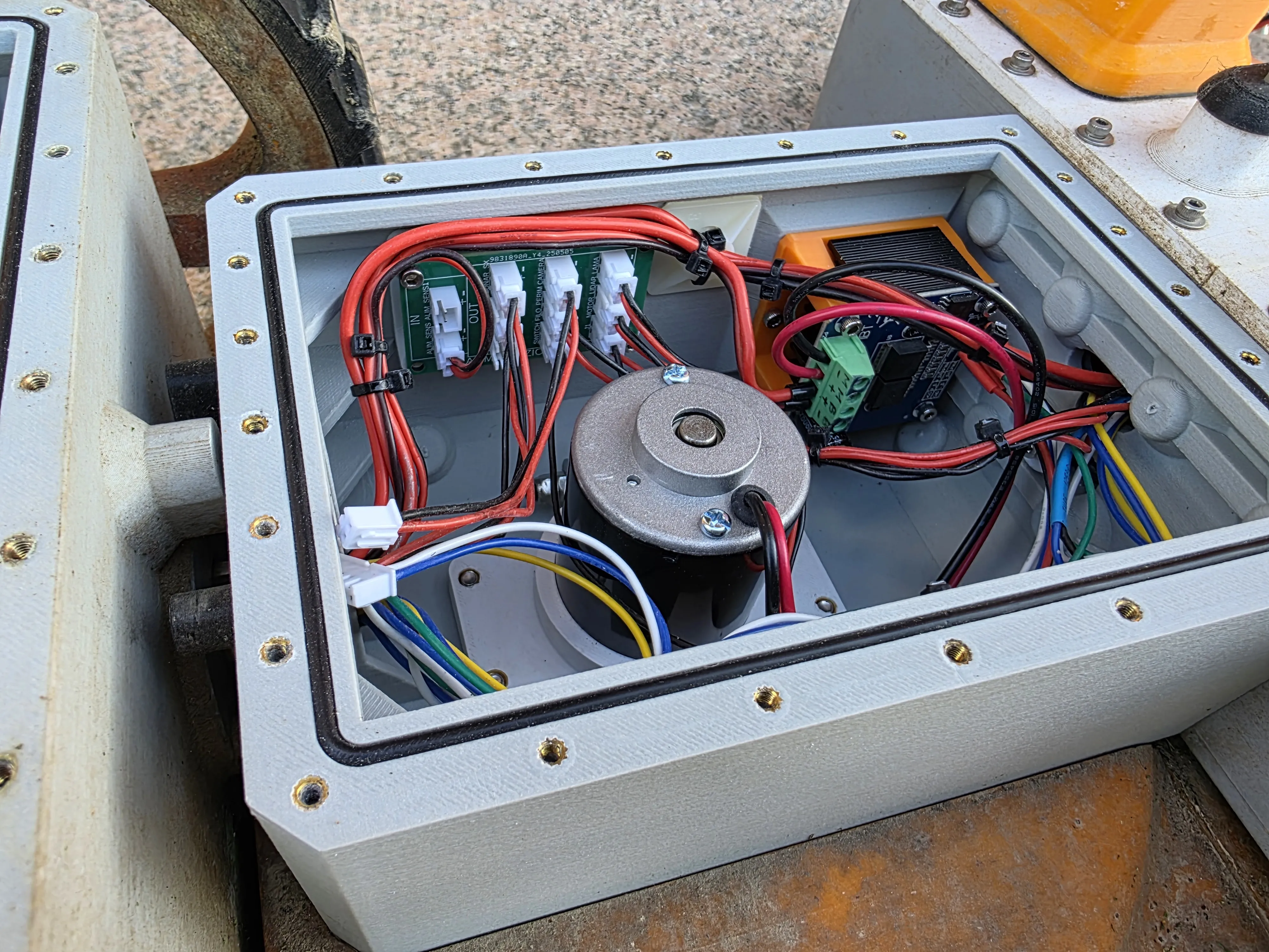
I created a PCB to mount on top of Arduino Mega where all connectors for the various sensors, power supply, and battery charging are installed This way, it's much simpler to make connections for all parts I also created a PCB to mount in the central shell that acts as a 5V power distributor This is intentional because the central hole, through which all cables must pass, has limited space This way, there is no need to run GND and 5V to each sensor located in the central and front shell
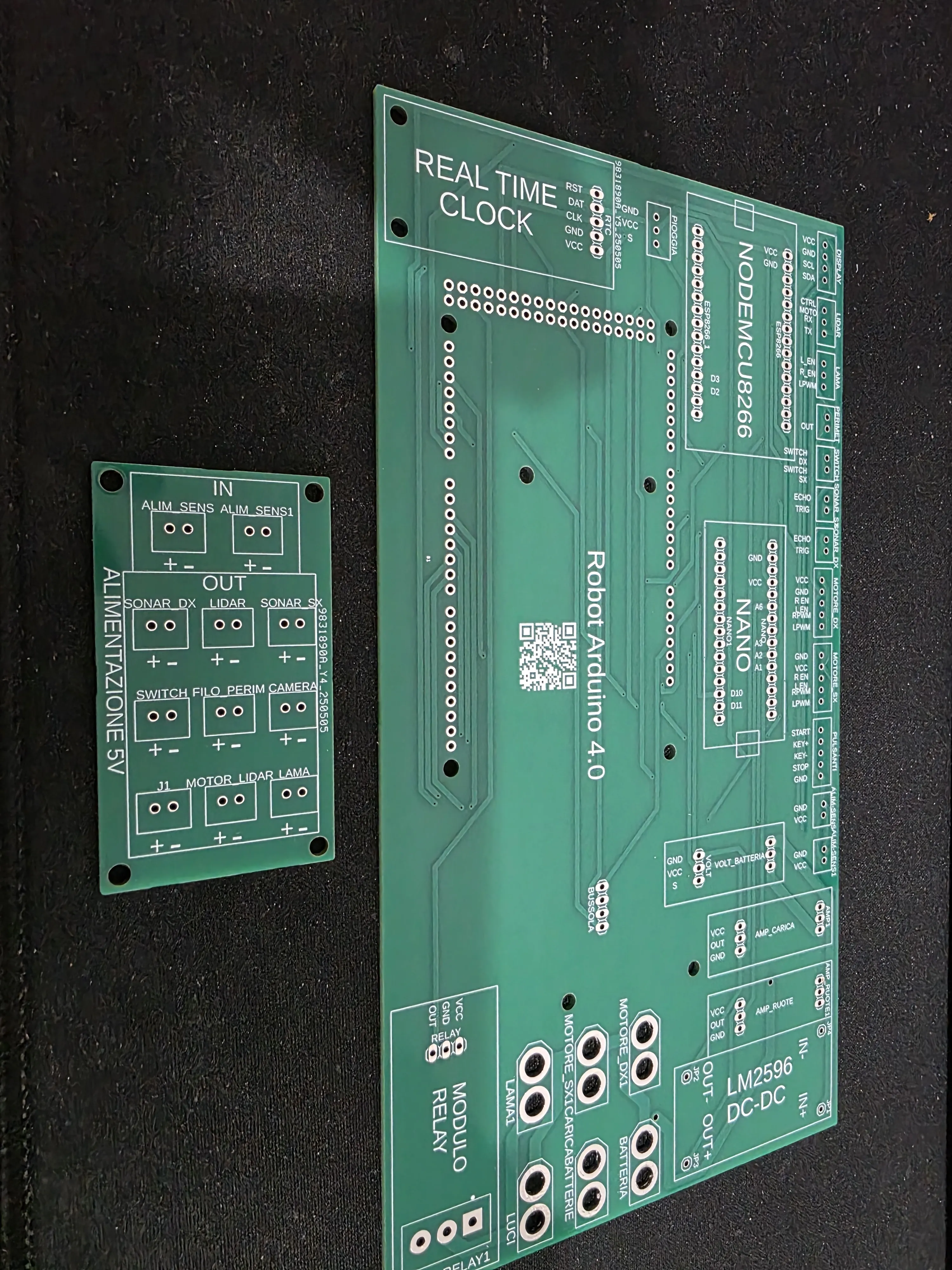
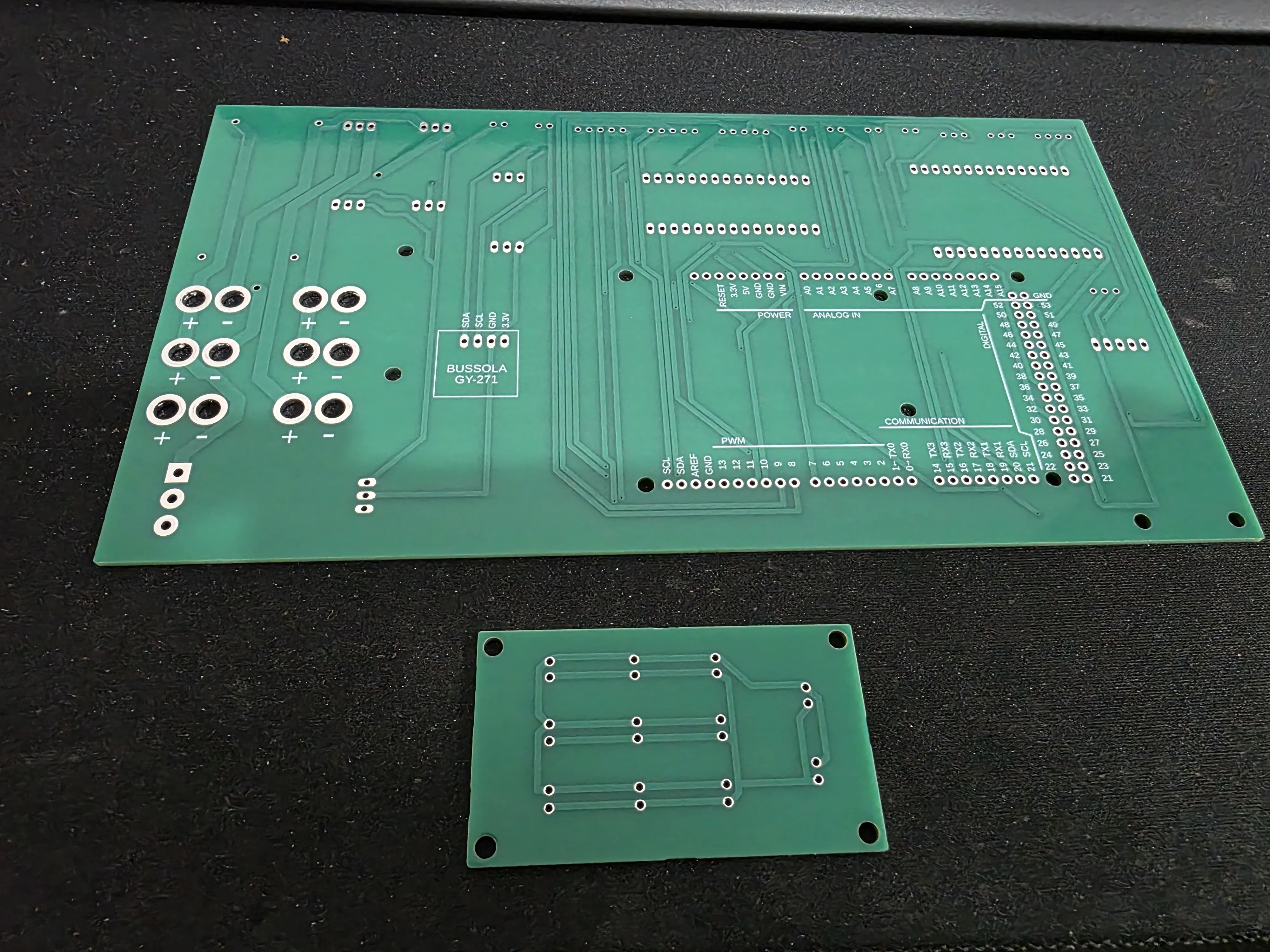
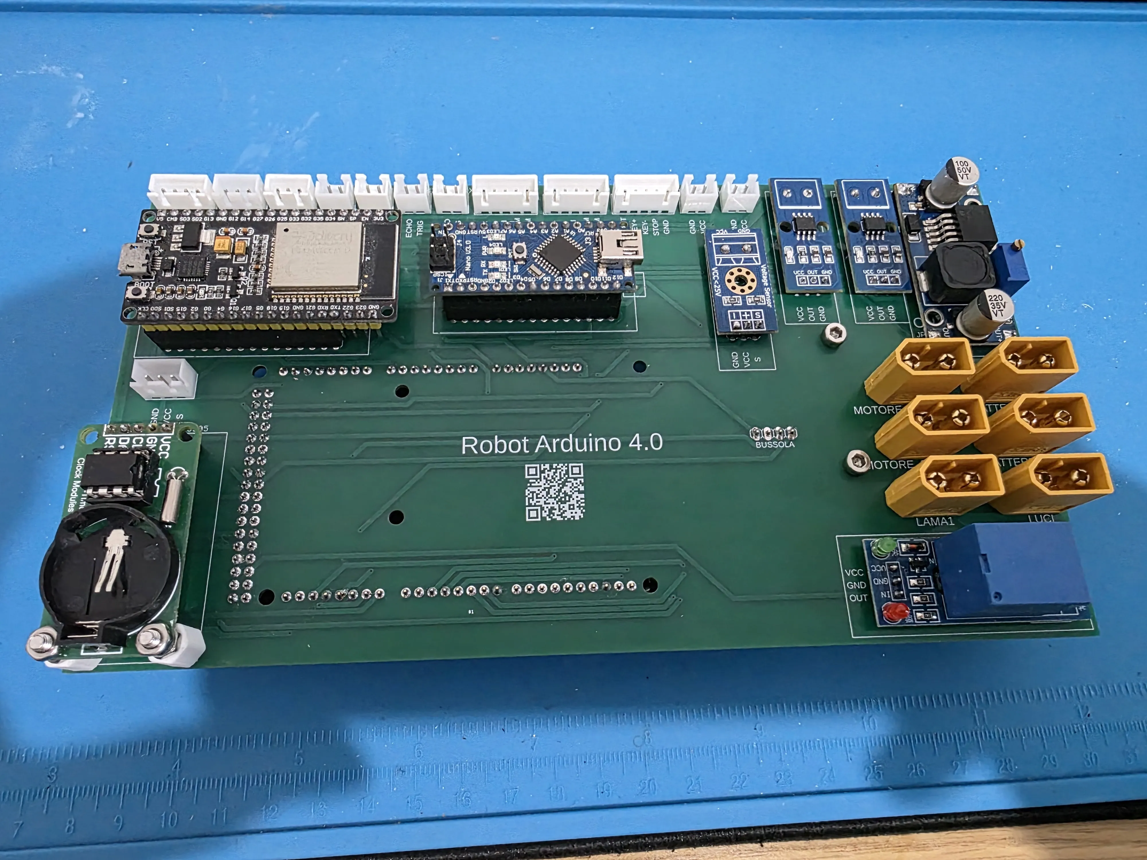
As seen in the photo, these are all the parts to be soldered onto the PCB that mounts on top of Arduino Mega The first thing to do is to remove (desolder) the existing pin headers and terminals from the voltage sensor, current sensor, and relay module This way, new pin headers can be placed on the opposite side, which are then used to solder the modules onto the PCB
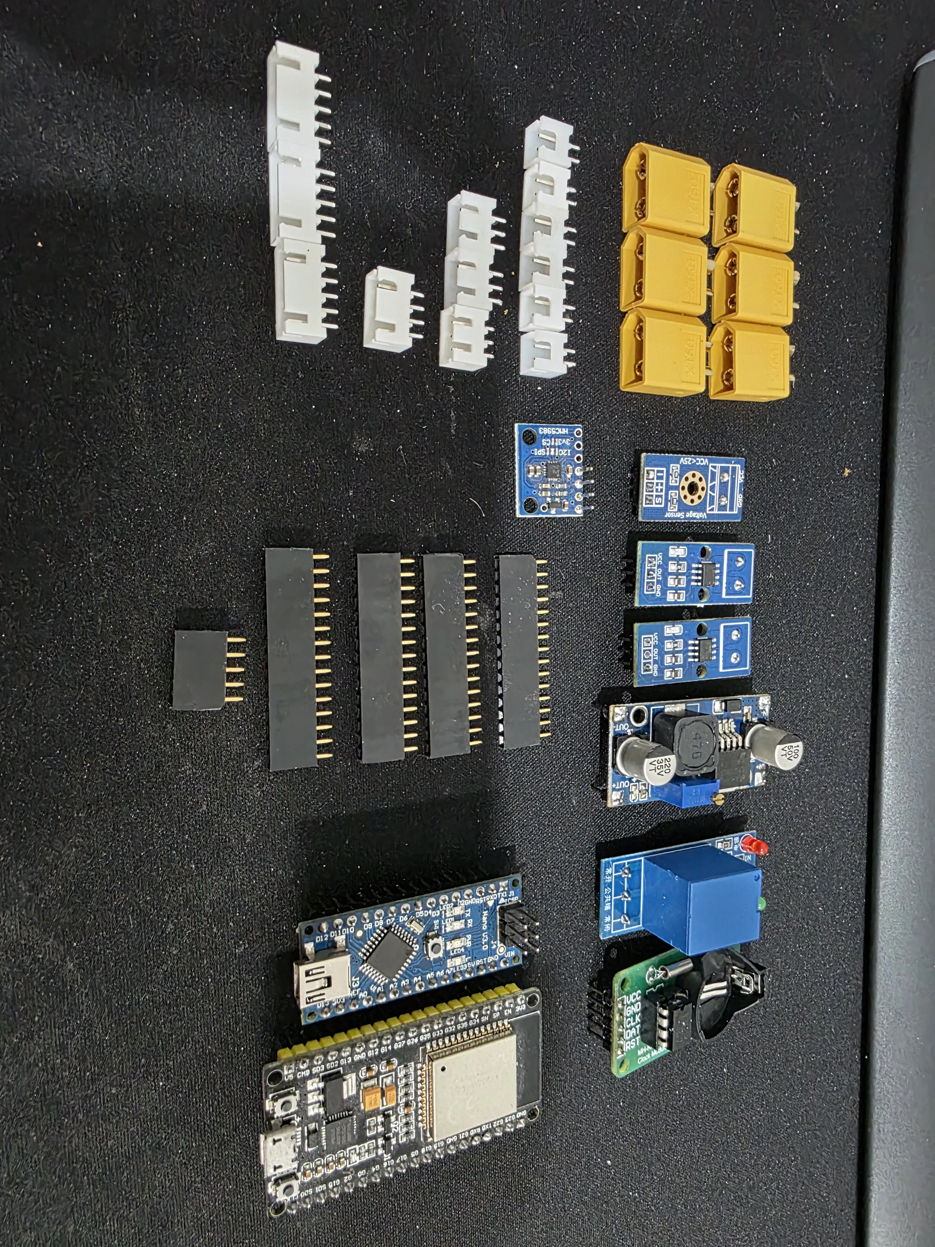
Then the next step is to solder the LM2596 DC-DC buck step-down converter into its position and solder the battery connector
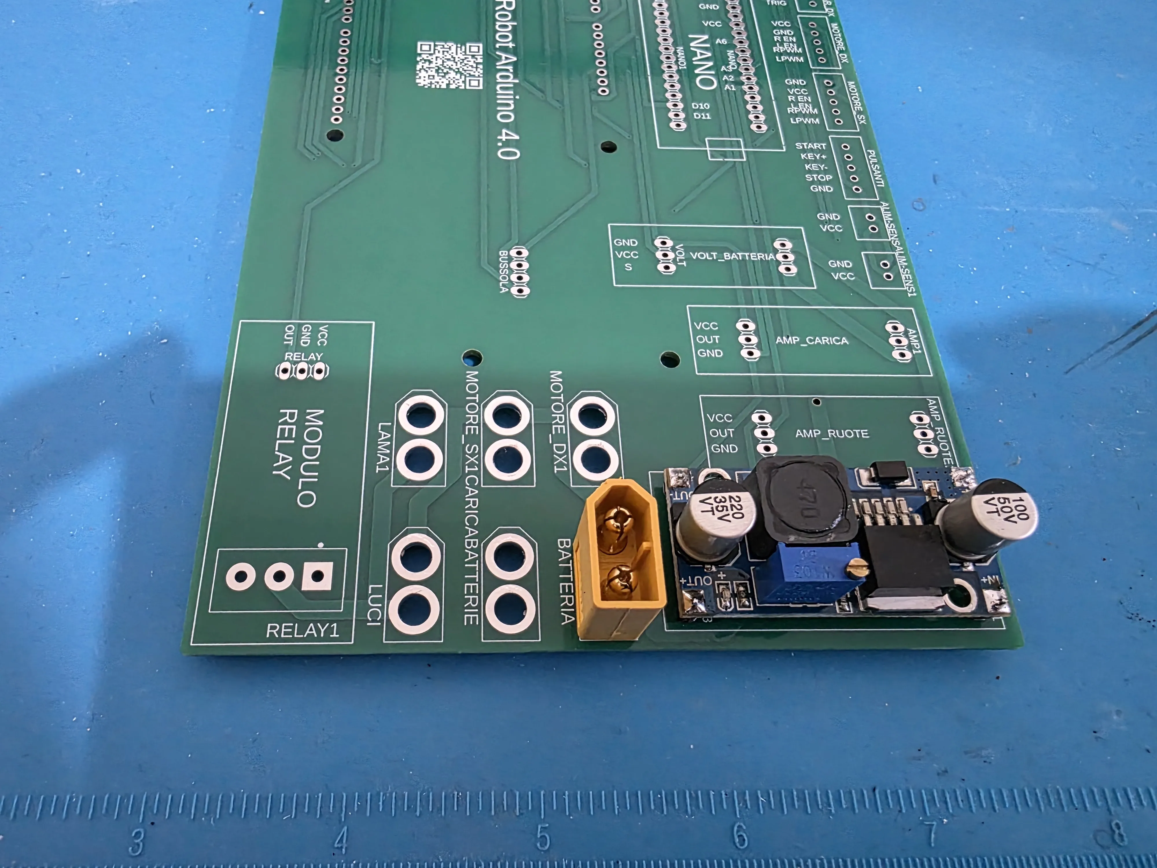
At this point, use a multimeter to adjust the OUT+ and OUT- output to provide exactly 5V It is highly recommended to perform this step before soldering everything else to avoid burning all modules, which, being soldered to the PCB, cannot be removed during this procedure
Subsequently, all remaining components should be soldered, starting from the lowest components to the highest
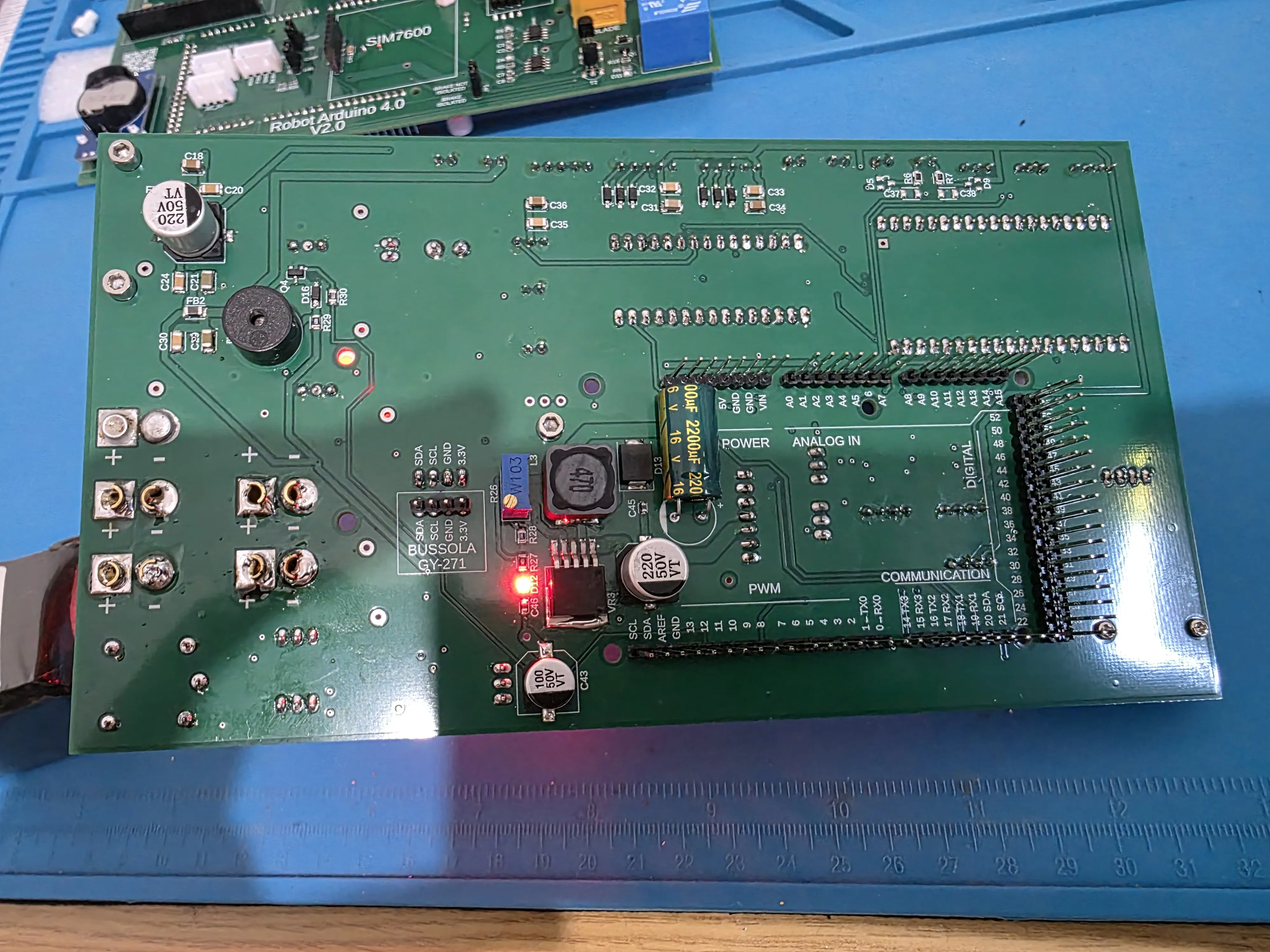
On the opposite side, the pin headers for mounting the Gy-271 compass must be soldered
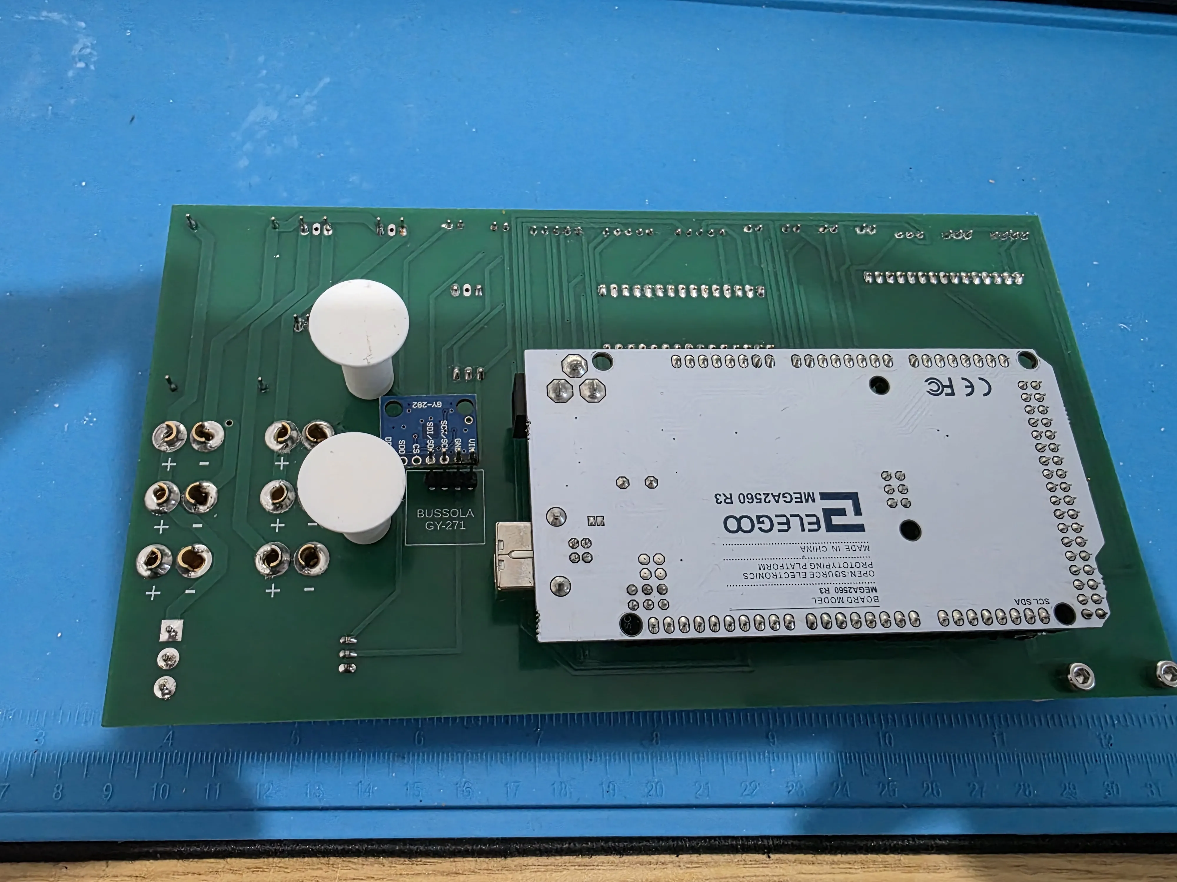
The only parts to print are the spacers to be placed between the PCB and Arduino Mega, the 2 support feet that are glued onto the cover, and the PCB support to be mounted in the central shell, also to be glued to the side (see photo)
For the 2 PCB supports and the distribution board support, M3 threaded inserts must be inserted into the holes
There are 6 inserts in total
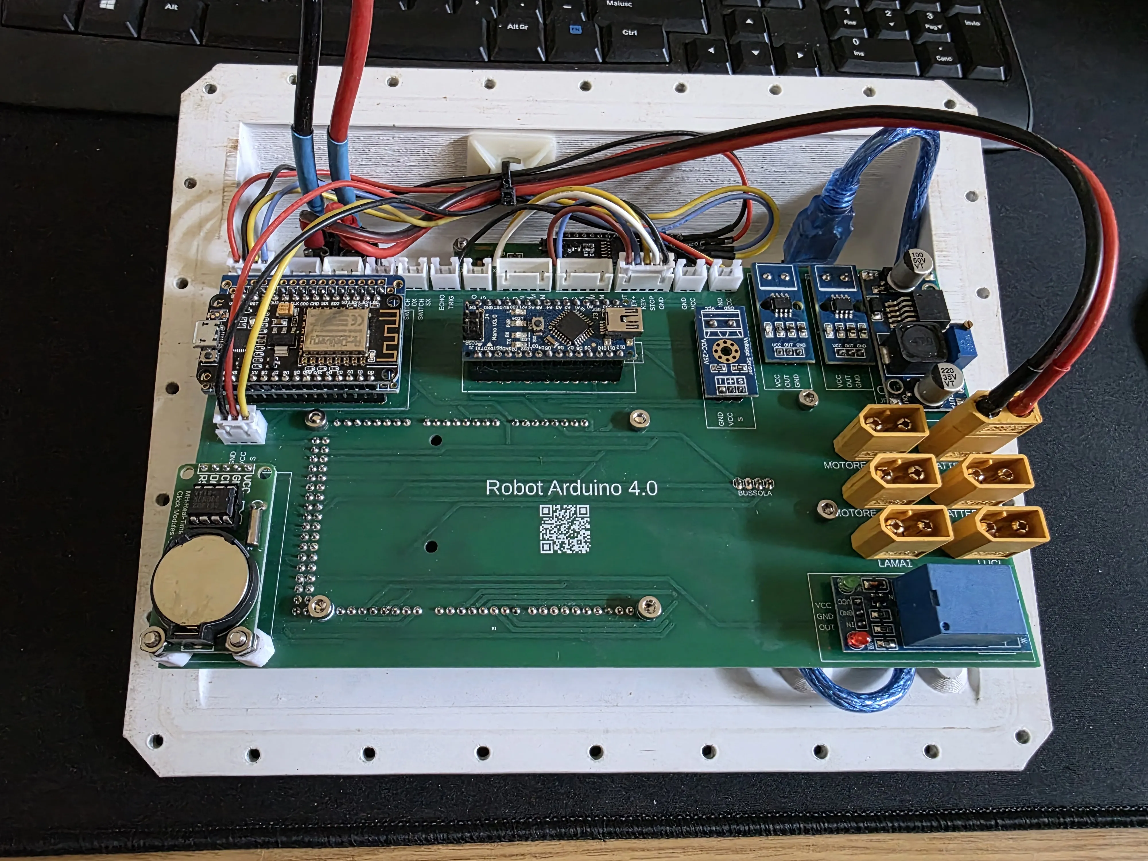
For those who would like these 2 PCBs, you can contact me here or via Messenger at the link: https://www.facebook.com/marco.bedendo.54
Update
Uploaded the print profile to mount a 400W 15A Step-up Boost converter with its support exactly above the wheel motor drivers This way, the robot always has the same voltage on the wheels regardless of whether the battery is low or fully charged, thus losing neither speed nor power The step-up must be adjusted to 16V before being mounted
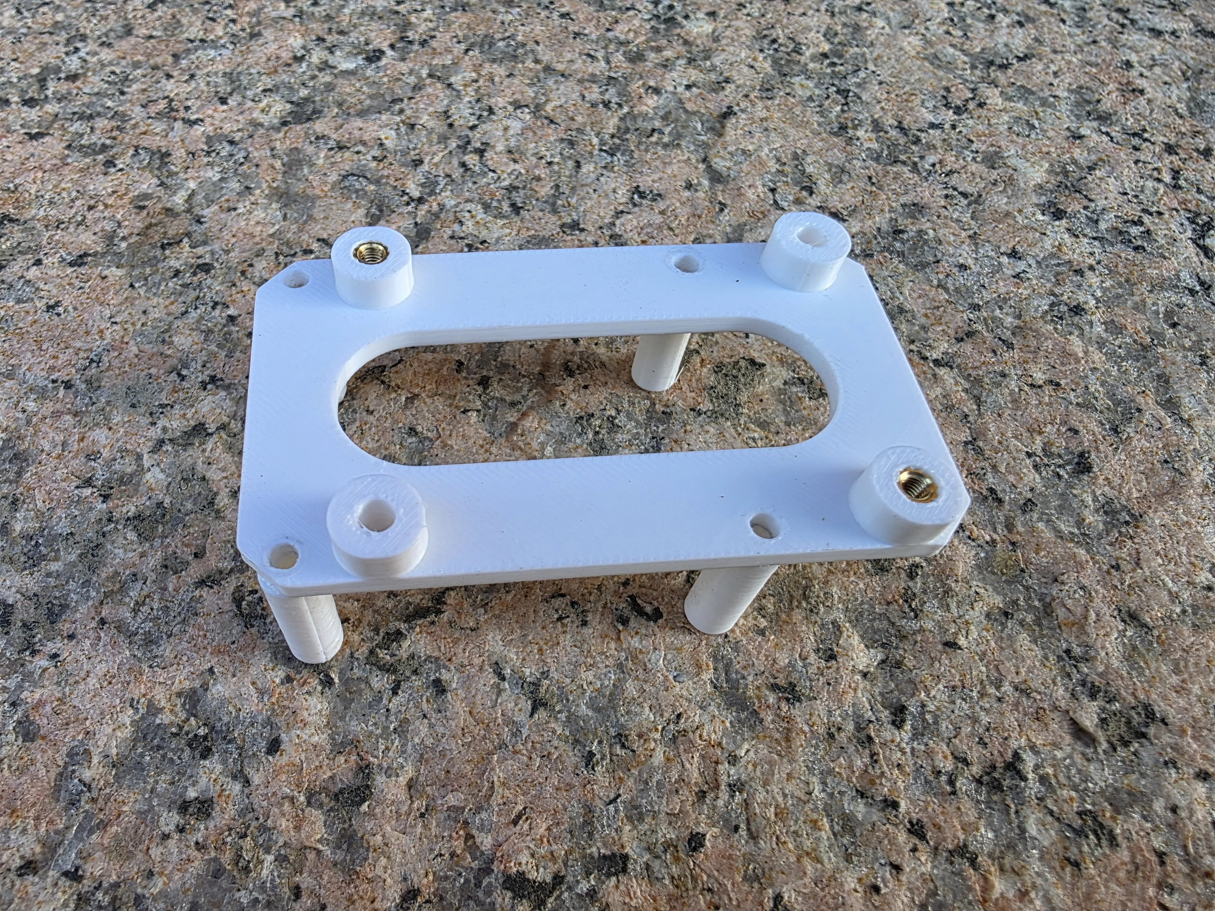
For ease of assembly, I glued the two spacers directly to the support to simplify mounting on the robot
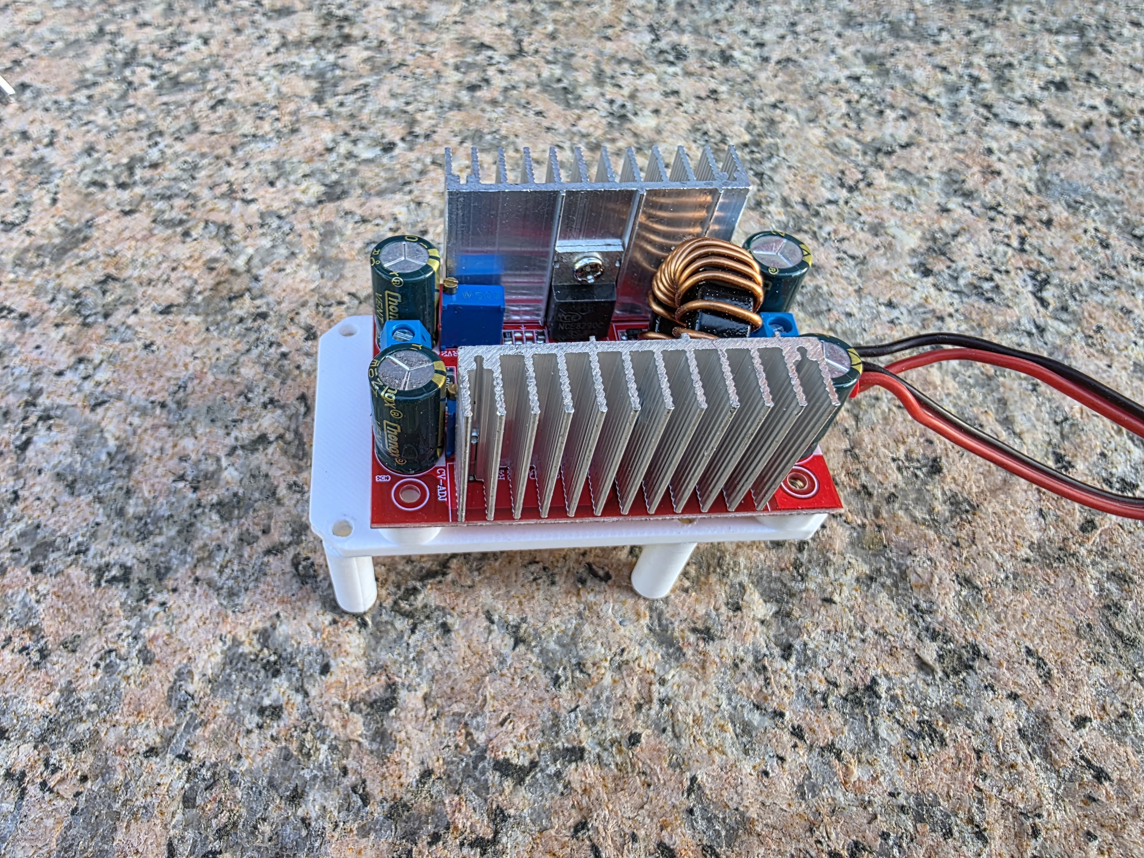
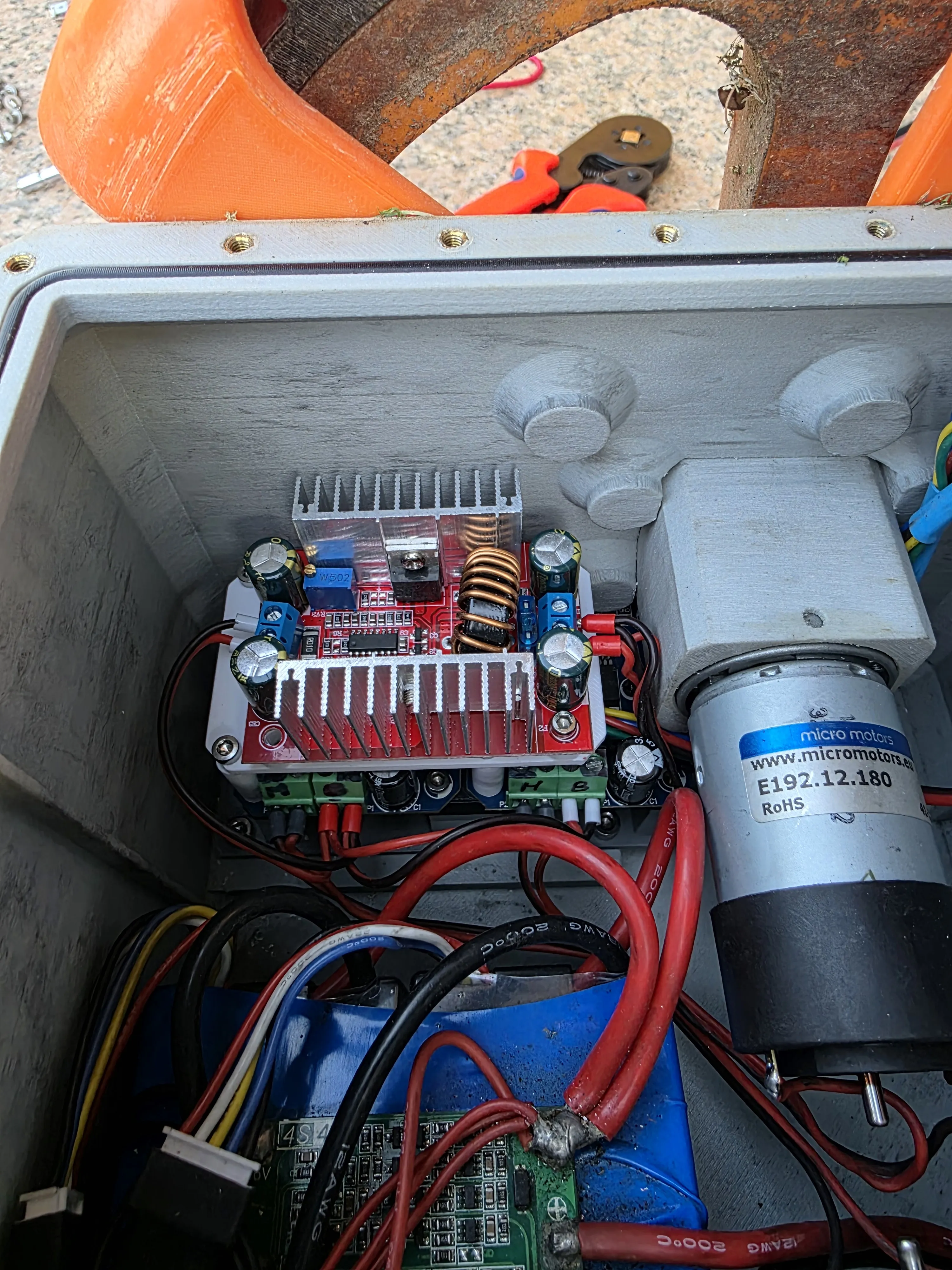
I kept the battery input on the right and the output towards the motor drivers on the left
For the modification, you need:
1 Pc DC 400W 15A Step-up Boost converter
4 Pcs M3 screw inserts
4 Pcs M3x30 stainless steel screws
4 Pcs M3x8 stainless steel screws
Update
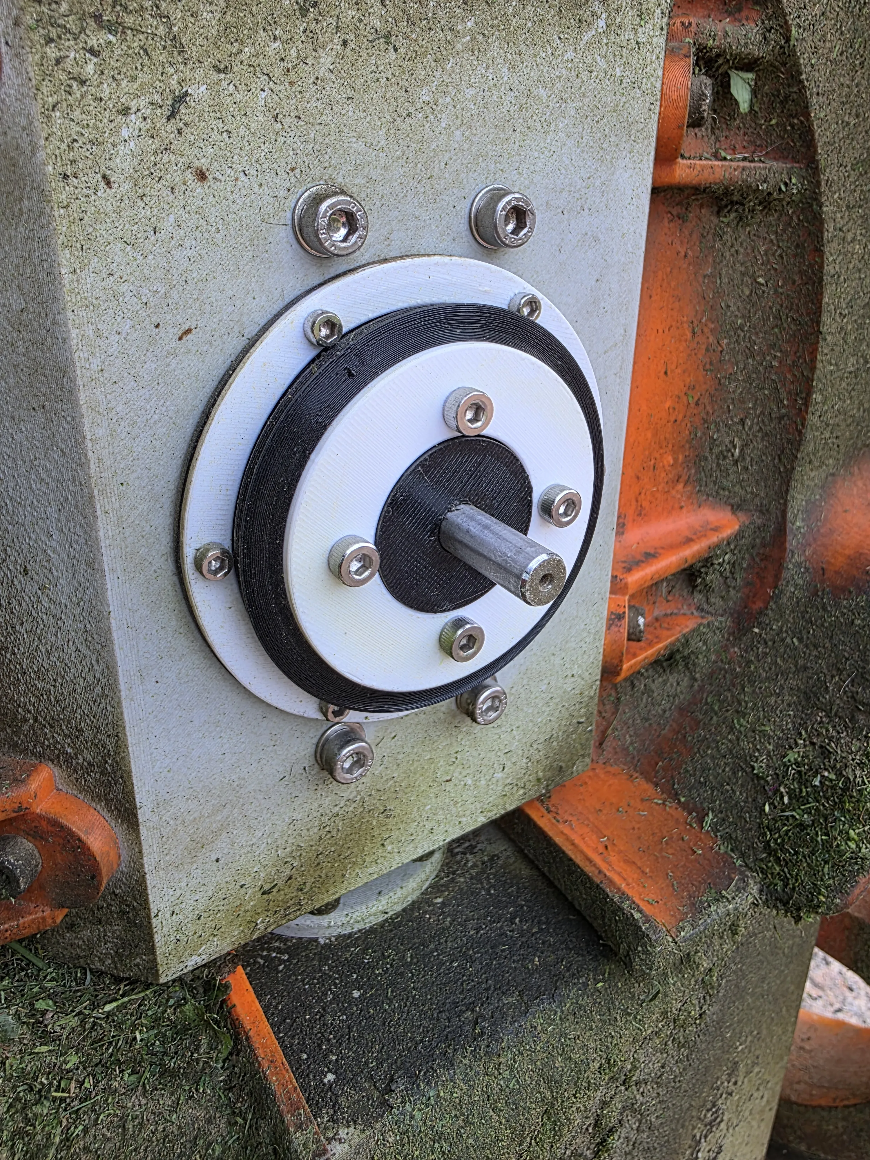
Uploaded the print profile to mount the new motor for the cutting blade This time, the motor is no longer brushed but brushless with higher power I also modified the articulated shaft that makes the robot jointed to facilitate cable routing Mounting this stainless steel component requires enlarging the bearing seat hole of the old shaft For those who do not want to enlarge the hole, I have also uploaded the modified rear shell with the modified hole The central shell is modified to accommodate the new motor and the new electronic components required for operation For those who do not wish to change the stainless steel articulated shaft, the parts are compatible with each other
For those who want to mount the new articulated shaft, they must remove the old bearings and install the new ones, placing a narrow spacer and a wider one between each bearing This way, the 3 bearings occupy the same space as the old ones
Materials for the modification
1 Pc 36V 138W 5.3A 57mm DC Brushless 3-phase 4-pole round shaft motor 57*57*87mm 0.33N.m 4000RPM BLDC motor 36V BLDC motor with Hall
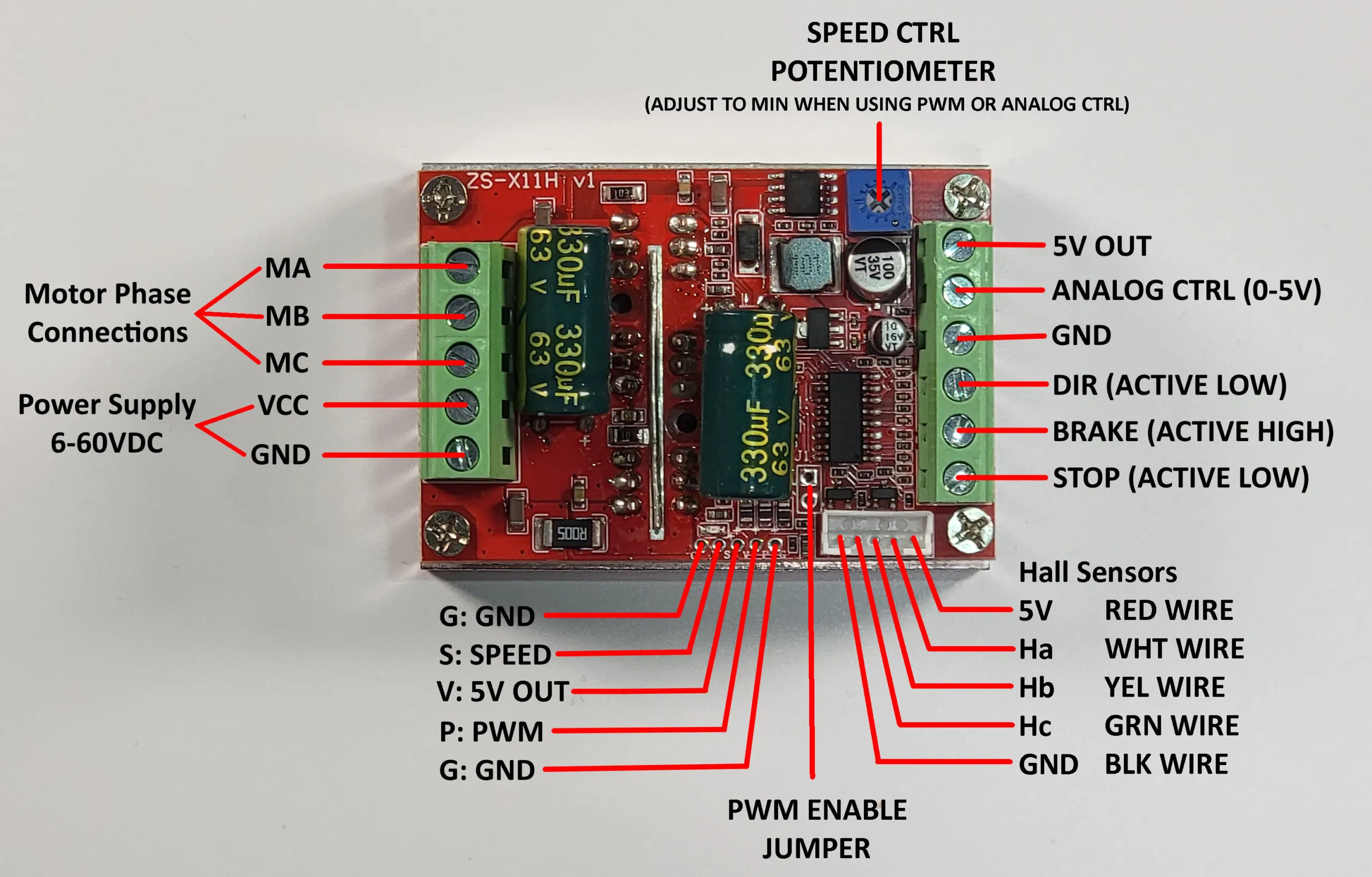
1 Pc DC 6-60V 400W BLDC Three-Phase DC Brushless Motor Controller PWM Hall Motor Control Driver Board 12V 24V 48V
1 Pc DC 400W 15A Step-up Boost Converter Constant Current Power Supply LED Driver Step Up Voltage Charger Module from 8.5-50V to 10-60V
1 Pc Ø8 stainless steel shaft-hub coupling
3 Pcs 6806-2RS bearing with dimensions 42x30x7
6 Pcs M3x12 stainless steel screws
4 Pcs M4x10 stainless steel screws
6 Pcs M3 brass screw inserts
4 Pcs M4 brass screw inserts
1 Pc M30x1.5 self-locking nut
Here you will find the new sketch modified to accept both brushed and brushless motors For the latest version, MEGA_1_7 requires the step-up to be installed on the wheel motors as well and calibrated to 16V output
https://github.com/Marcobedendo78/Robot-Arduino-4.0
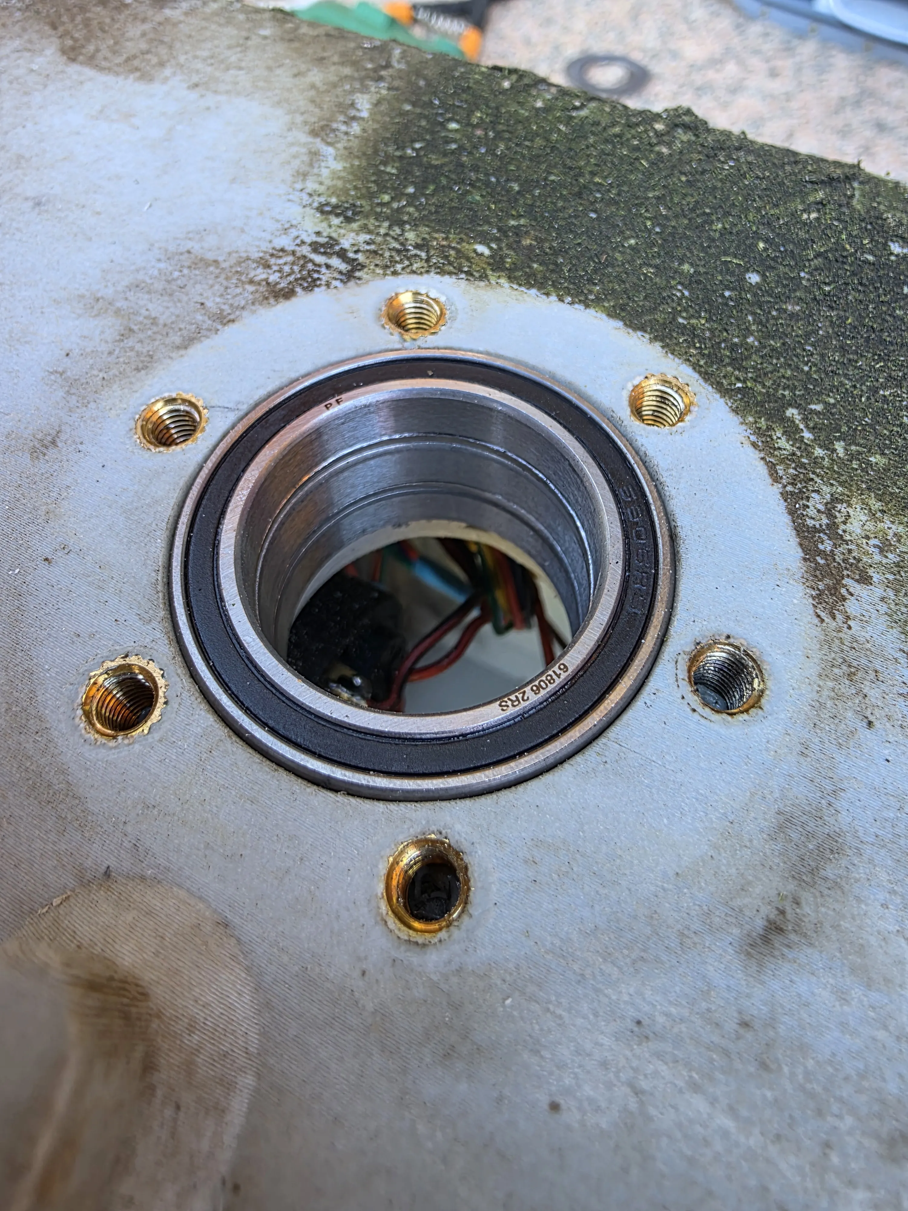
Next, the new closing flange for the new shaft must be mounted I recommend lubricating everything before inserting it
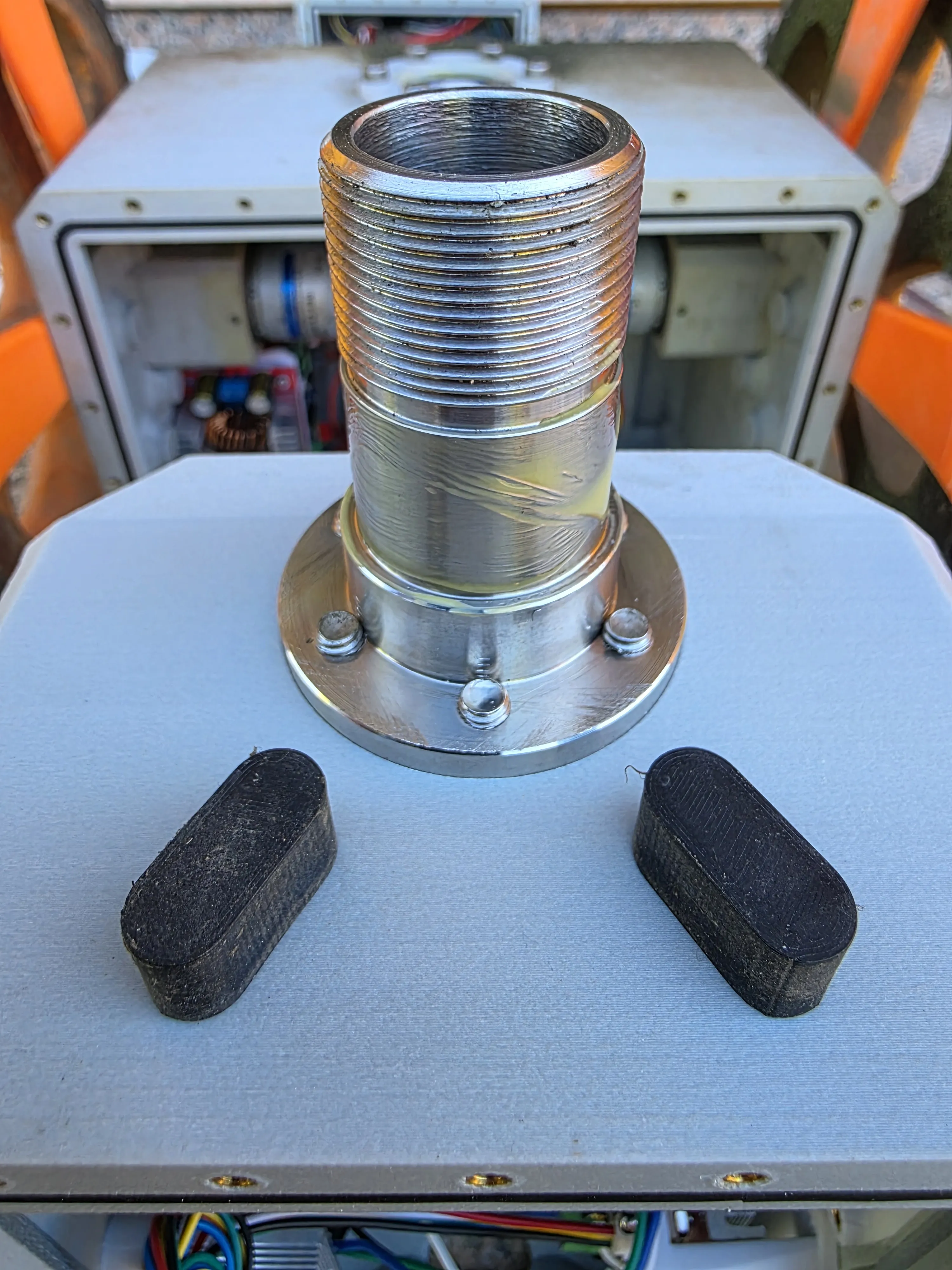
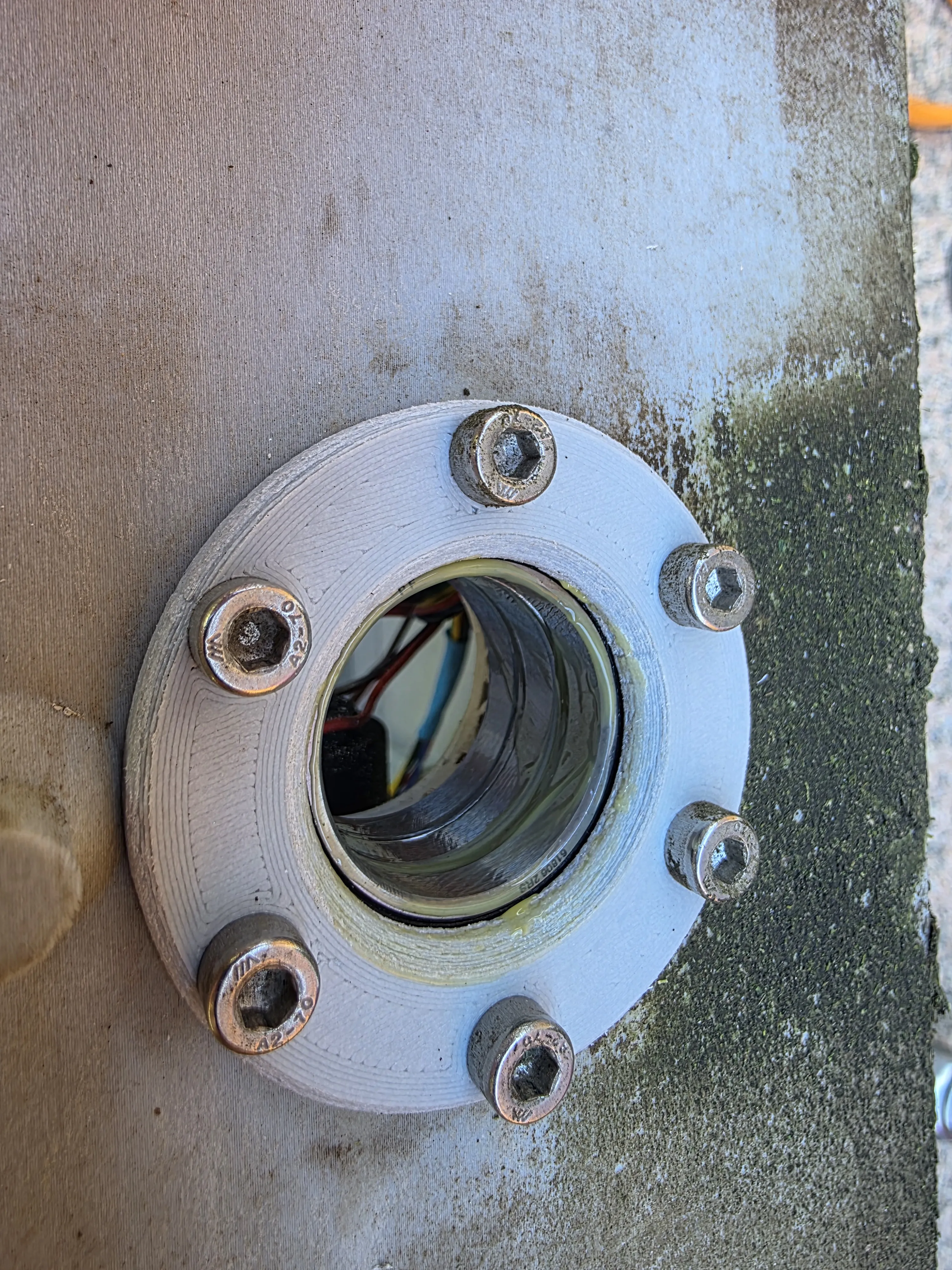
Then, inserting the new shaft, the spacer and then the locking nut must be placed to form the bearing pack and secure everything Having the possibility, I made the parts in metal, but I uploaded the print profiles to make them in PETG-CF with 100% infill I used 2 nuts because I didn't have the self-locking version, but if desired, one is enough as long as it is self-locking
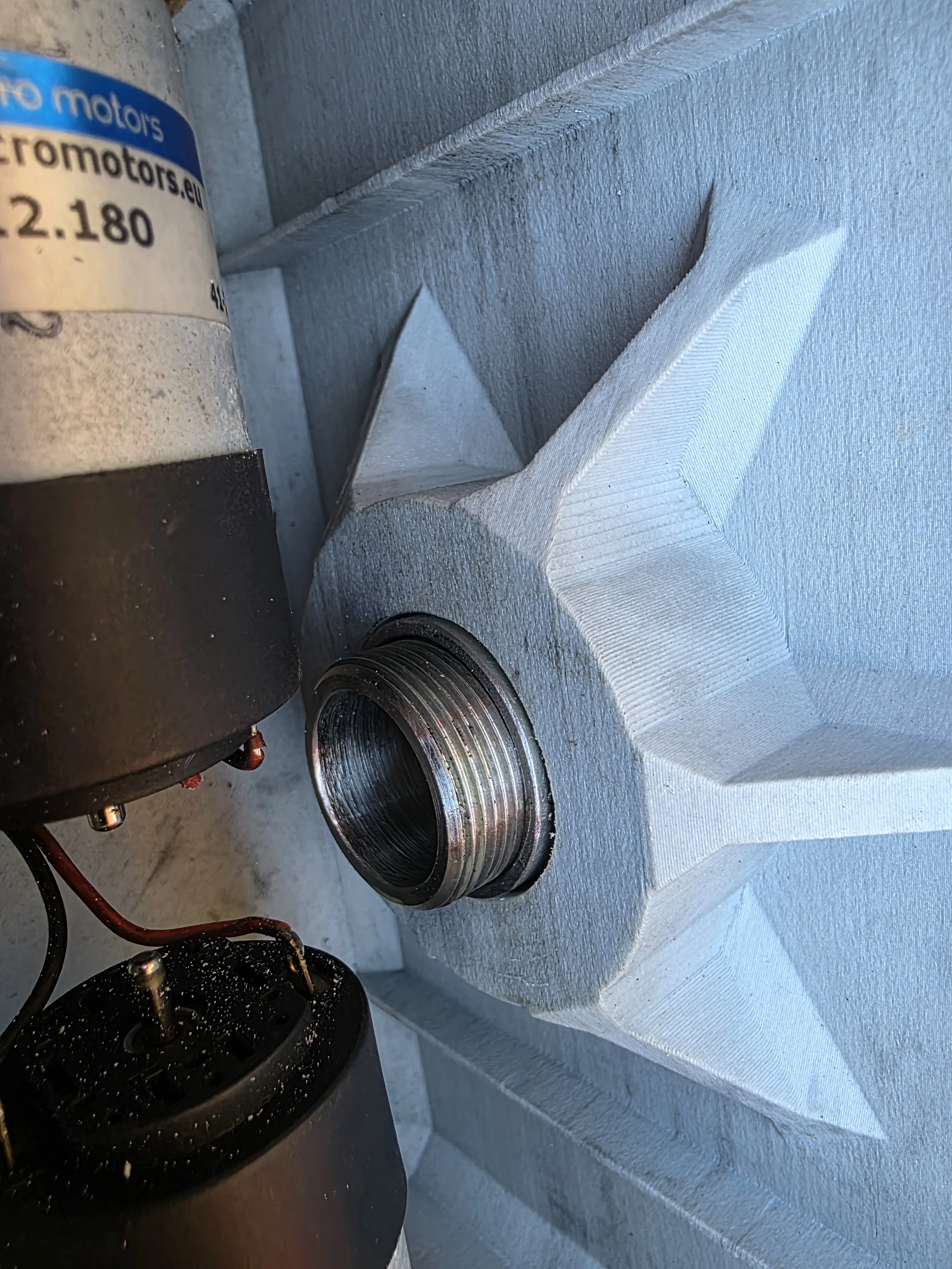
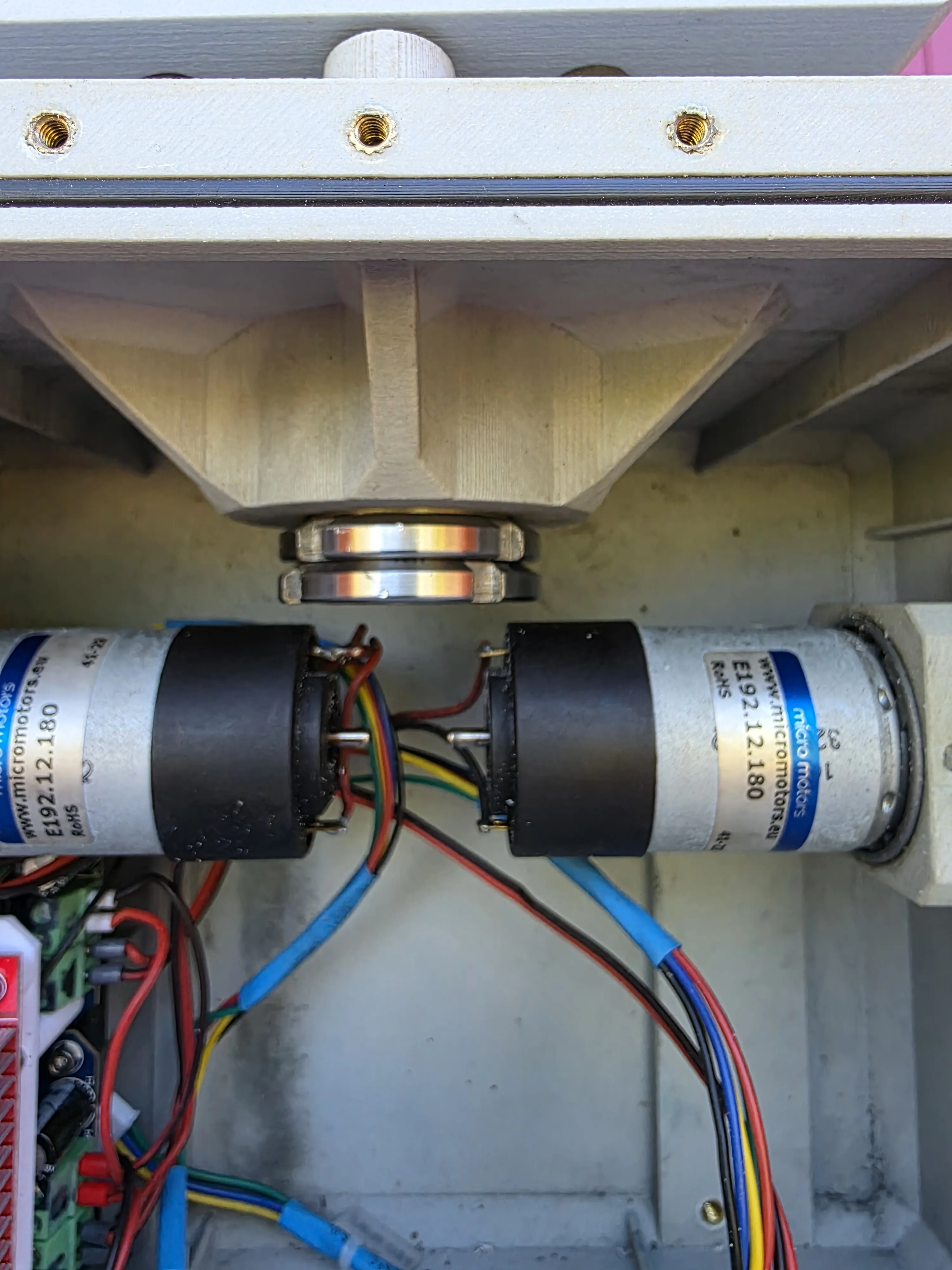
At this point, the new shaft can be screwed to the central shell
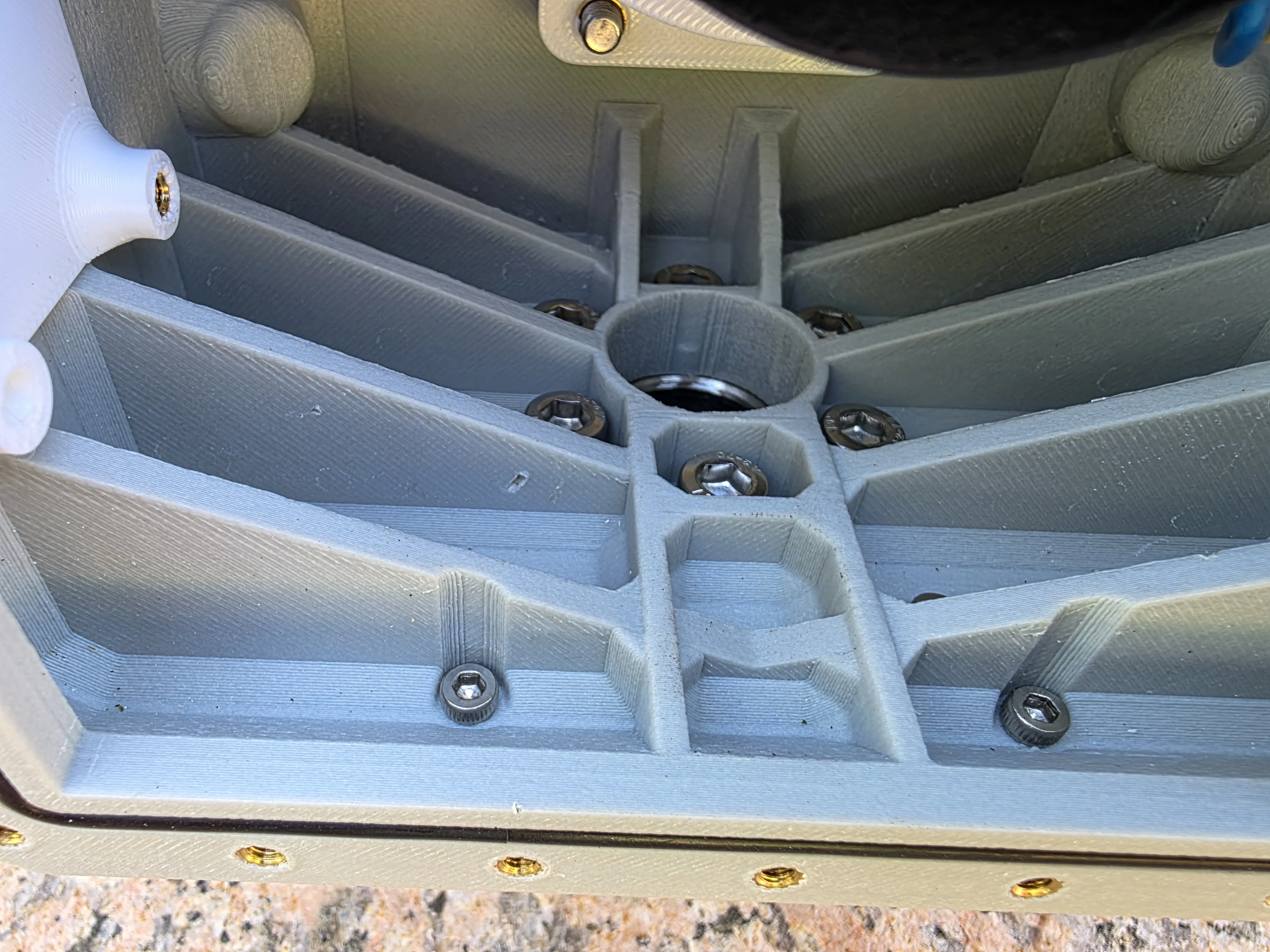
Then the motor driver must be mounted on its respective support, the wiring prepared on it, and then inserted into the shell It must be screwed onto its support with M3 screws and nuts between the board and the heatsink To insert it into the support, slide it in from a short side
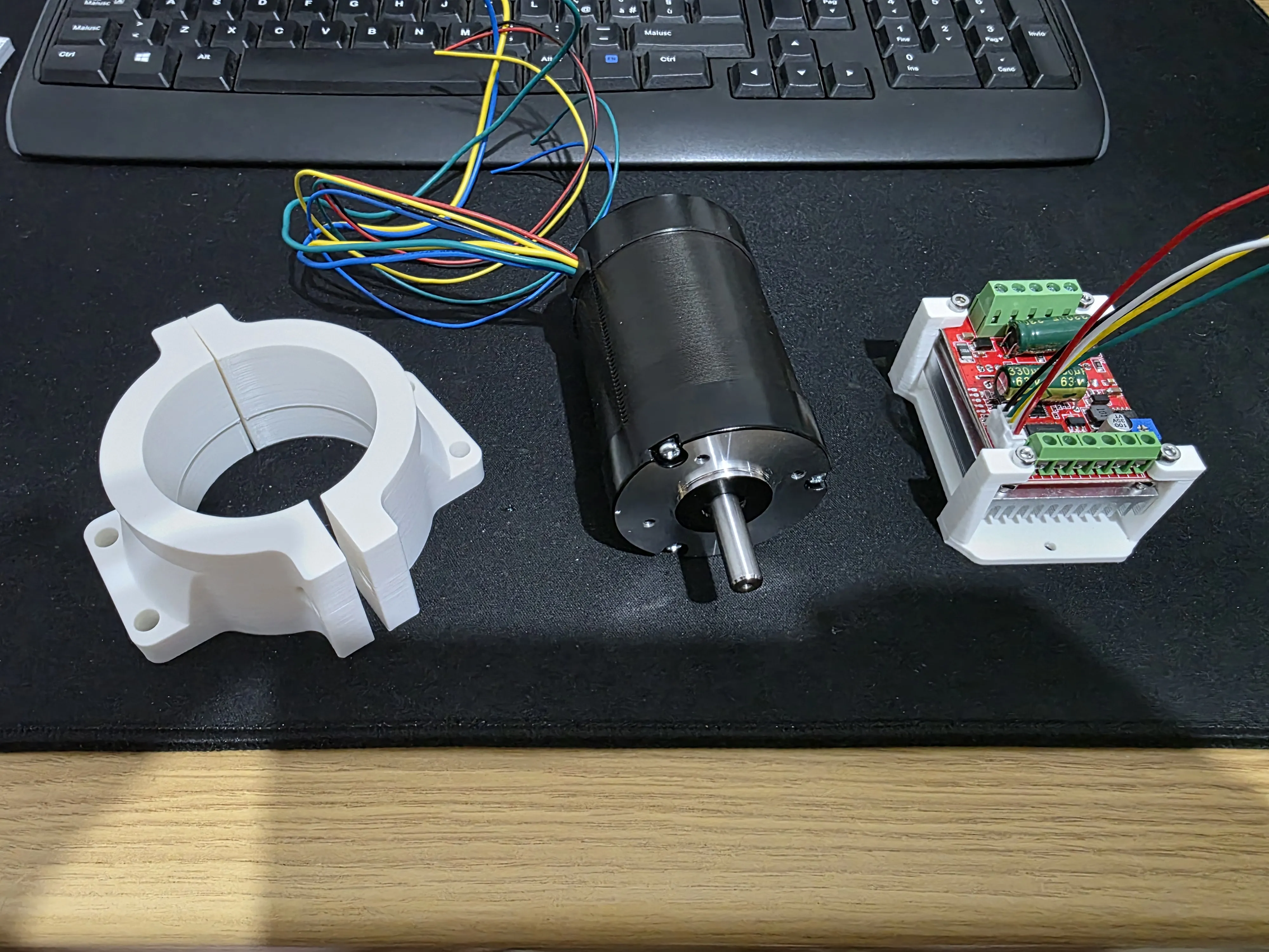
On the driver, a cable must be soldered to the hole marked P: PWM, which must be connected to the L_EN pin of the PCB, the pads next to the capacitor must be jumpered, and then the wires of the motor's Hall sensors must be connected to the wires provided with the driver, respecting the A-B-C phases of the motor and 5V and GND
Then the terminal block pin marked BRAKE must be connected to the R_EN pin of the PCB, the terminal block pin marked DIR to the LPWM pin of the PCB, and the terminal block pin marked GND to the GND of the PCB that distributes the 5V power supplies In the large terminal block (the one with 5 inputs), the motor phases and the power coming from the Step-up must be inserted
I used the BRAKE pin instead of the stop pin because this way, when the command to stop the motor arrives, it stops immediately; if the STOP pin is used, the motor spins by inertia until it stops
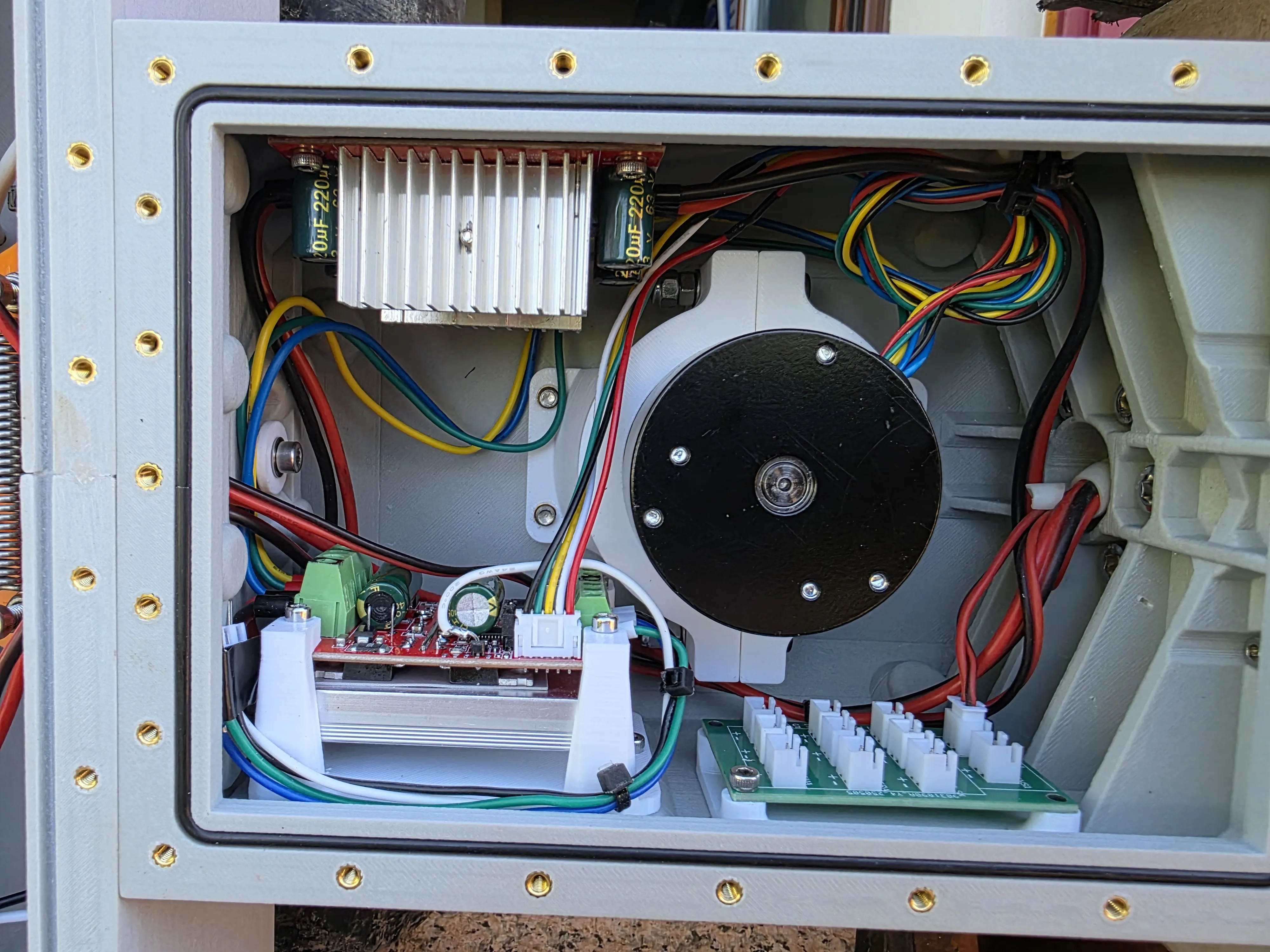
The Step-up must be adjusted to 30V using the trimmer marked RV1 and adjusted to 5A with the trimmer marked RV2 before installation The 4 holes must also be enlarged with a 3.5 drill bit Then the spacers are screwed to the step-up and it is glued into the shell For convenience, I screw it with only two screws, making it easier to remove if needed The terminal block with IN+/IN- indicated should be kept towards the rear shell I also attach photos of the driver connections
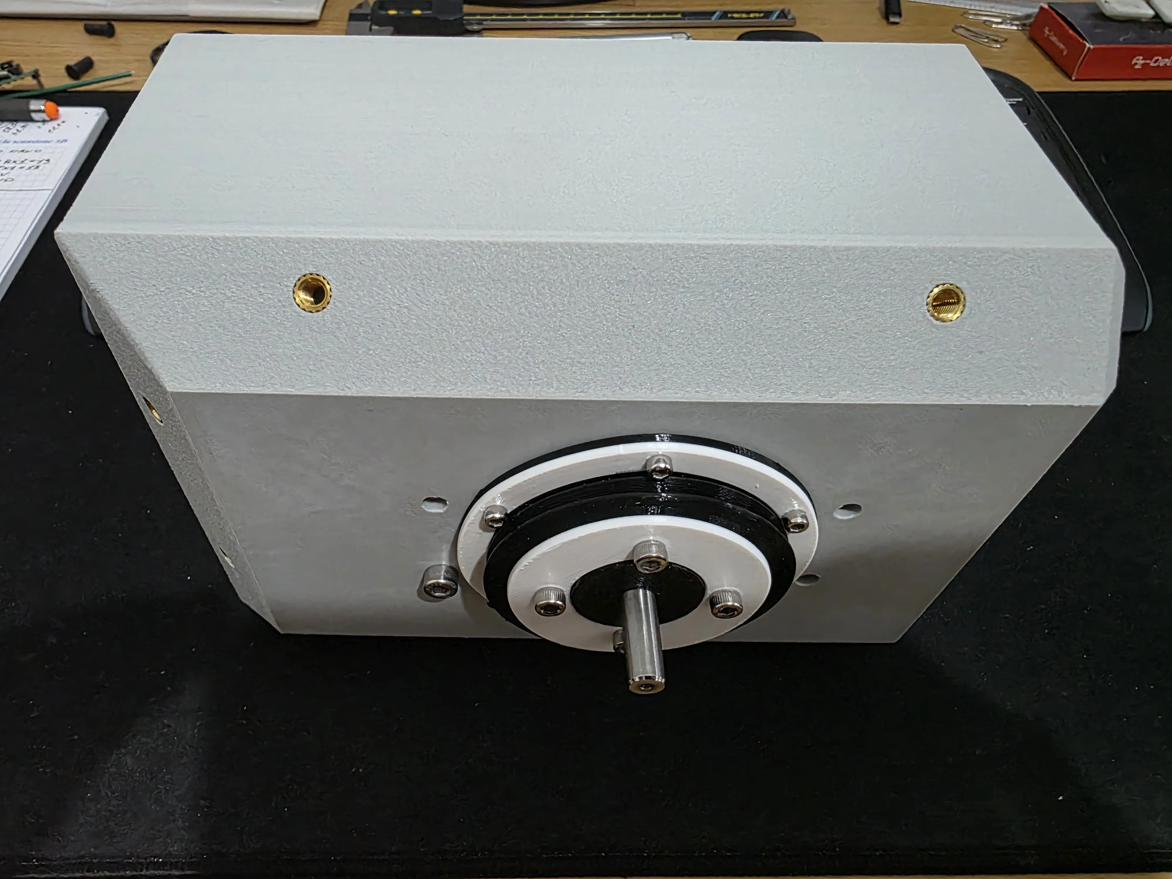
Once everything is connected, the motor is secured in its support and fixed to the shell like the old motor (The old motor can also be mounted in this version because the holes are the same) At this point, the protective bellows are put in place and secured with the ABS rings
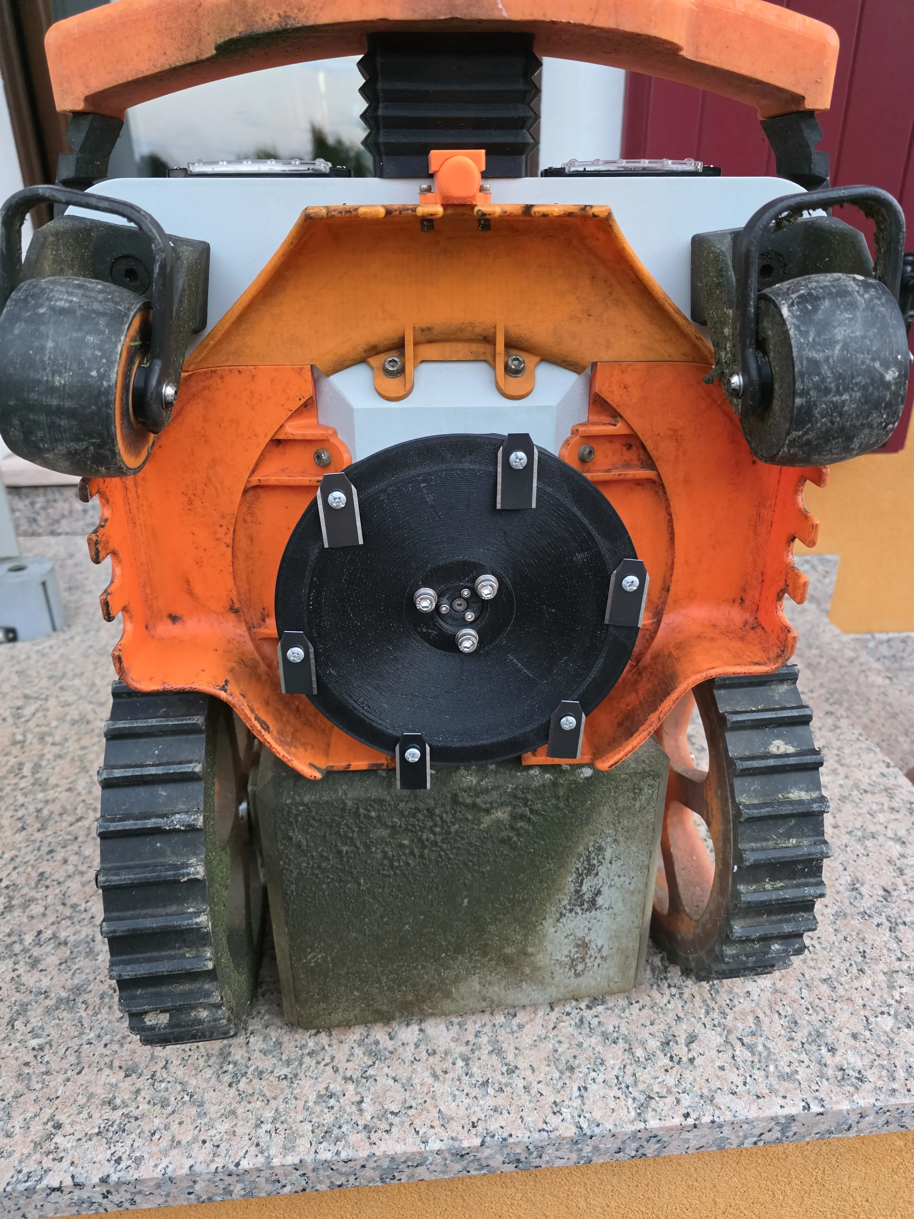
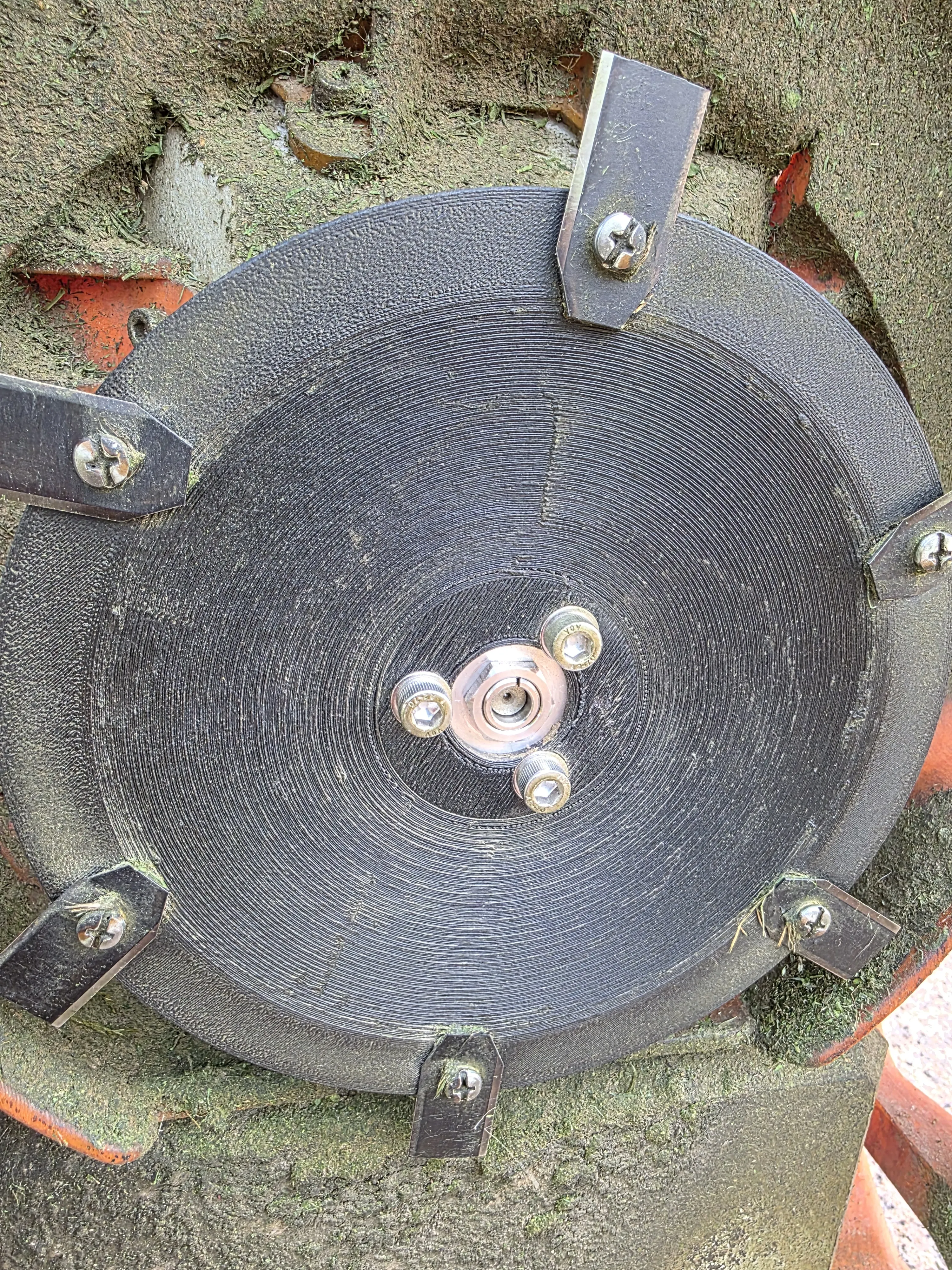
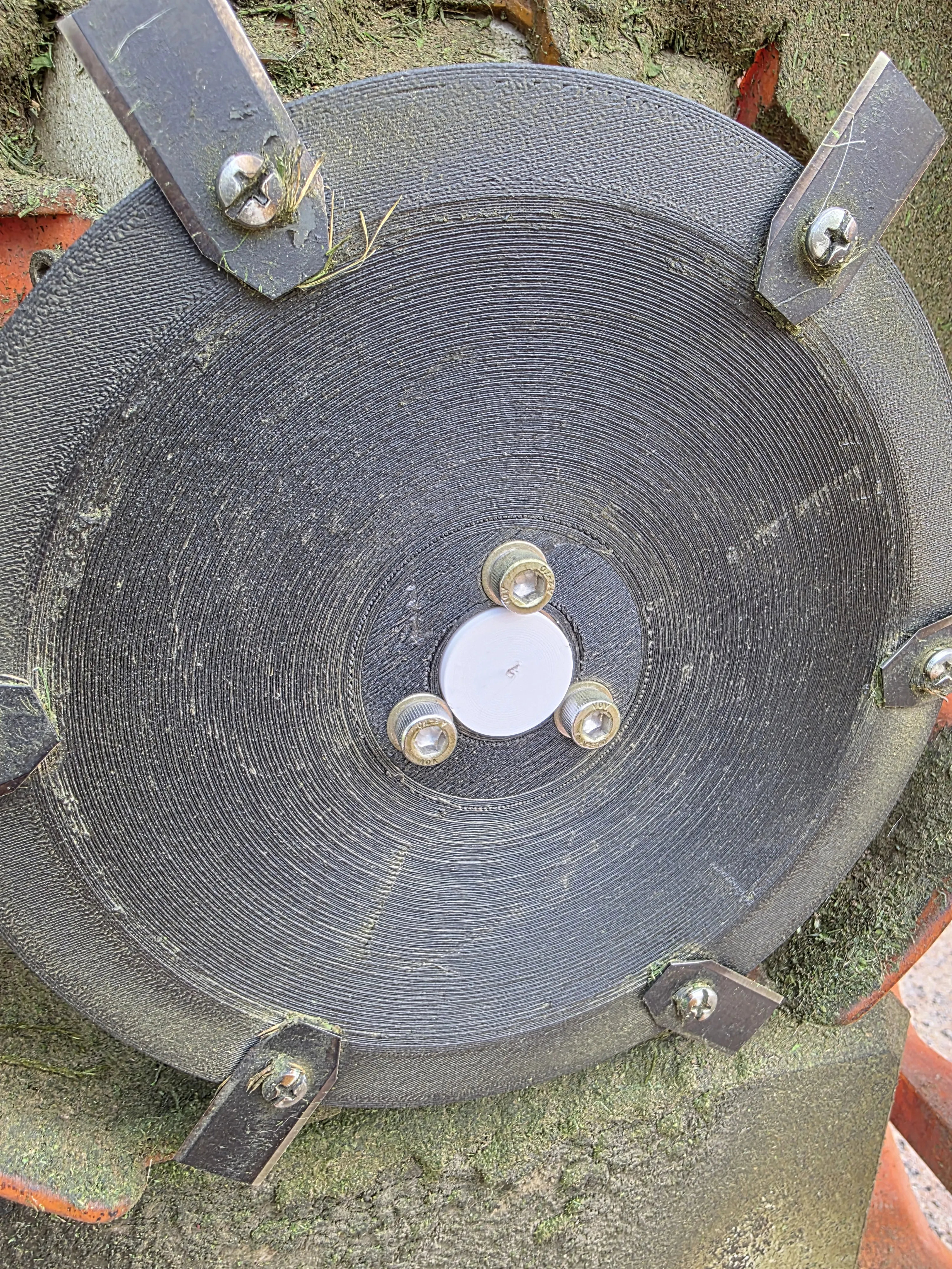
At this point, once everything is assembled and connected, all that remains is to mount the cutting disc support and its coupling I made the support from aluminum and mounted the commercial stainless steel coupling, but I also created a plastic support instead of the aluminum one I also tested a completely plastic version for those who do not want to buy a stainless steel coupling, which includes the cutting disc support and the coupling entirely in PETG-CF with 100% infill
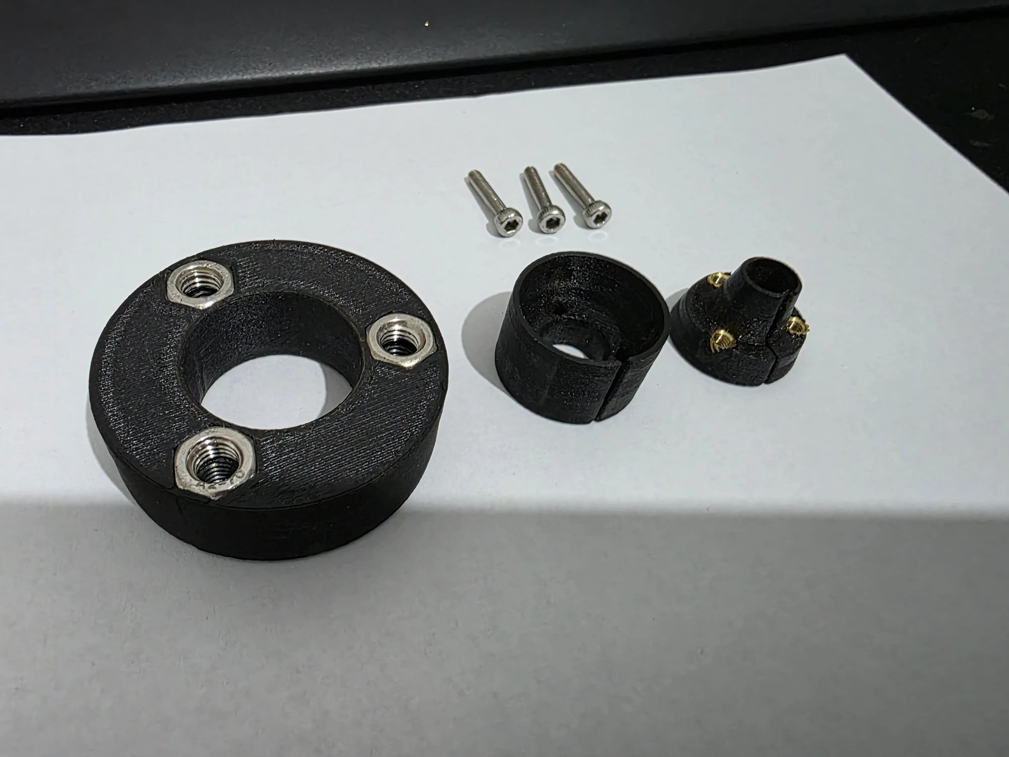
To use this version, I recommend first inserting the outer part of the coupling (the one with the 3 holes) completely into the cutting disc support
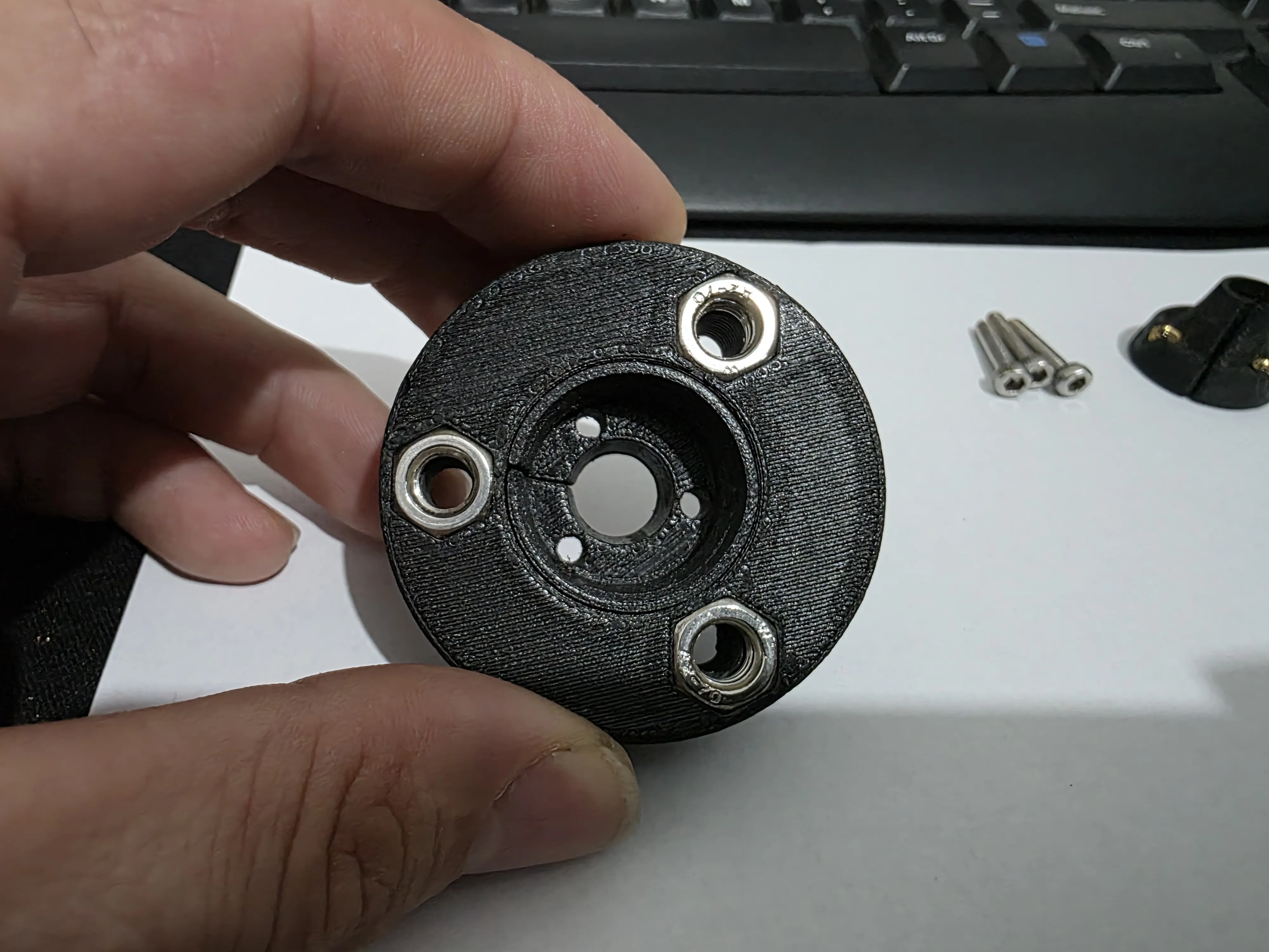
then insert the inner part of the coupling with the threaded inserts already mounted, trying not to align the open part with the other
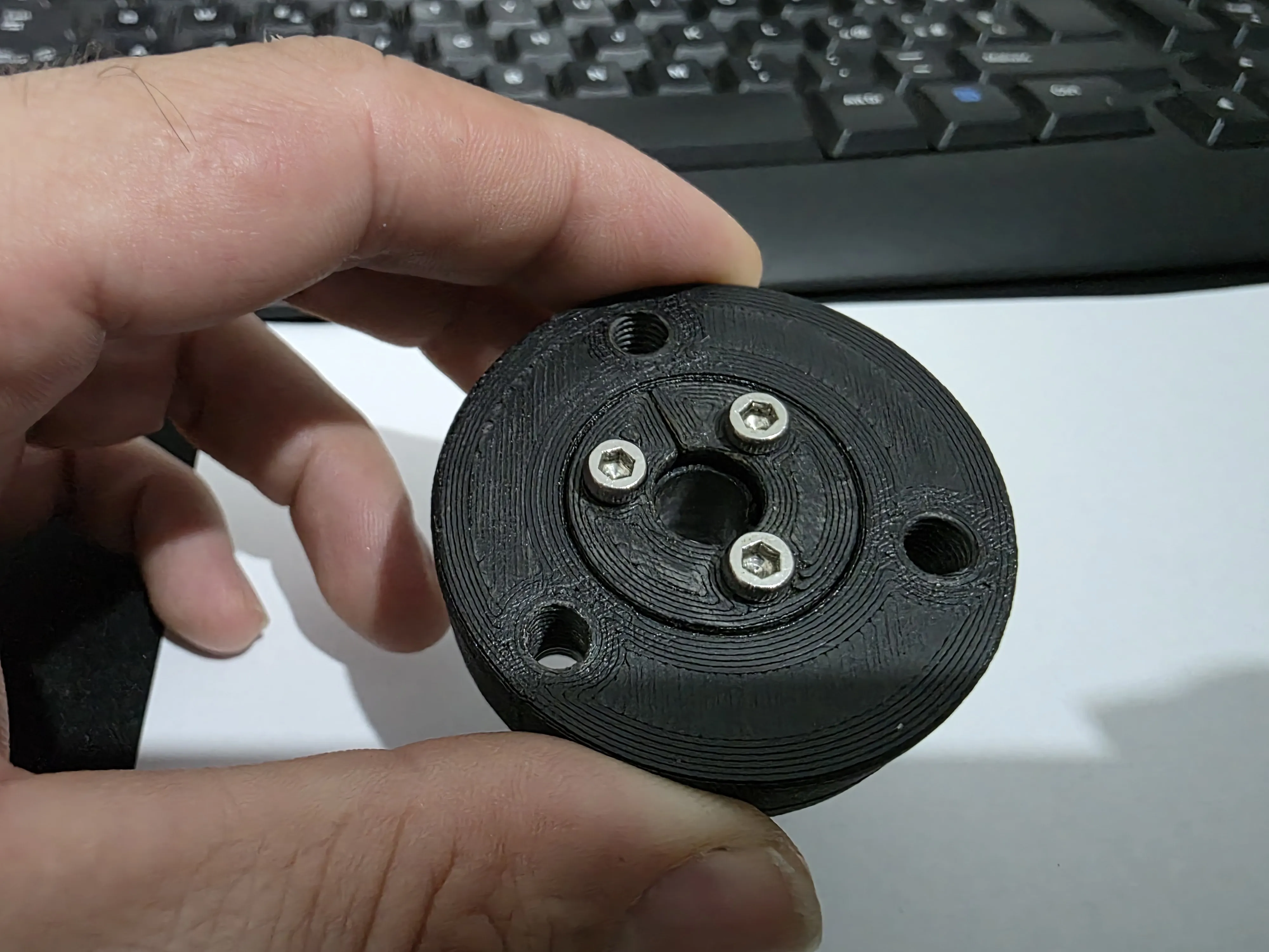
At this point, insert it onto the motor shaft, trying to keep it flush when fully tightened As it tightens, it will go further down, so start with it a little more protruding I recommend tightening the screws a little bit for each one, otherwise the disc will turn crooked When I had tightened it enough, I mounted the cutting plate with the 3 screws, trying not to let them protrude from the opposite side, and by turning it by hand, I could see where the screw needed more tightening This operation only needs to be done once; then, when removing the cutting plate for maintenance, there is no need to remove the rest from the motor shaft
With the commercial coupling, this precaution is not necessary because it is self-centering, and furthermore, I created a closing cap to protect it because with this, the motor shaft is more internal and not flush
Update
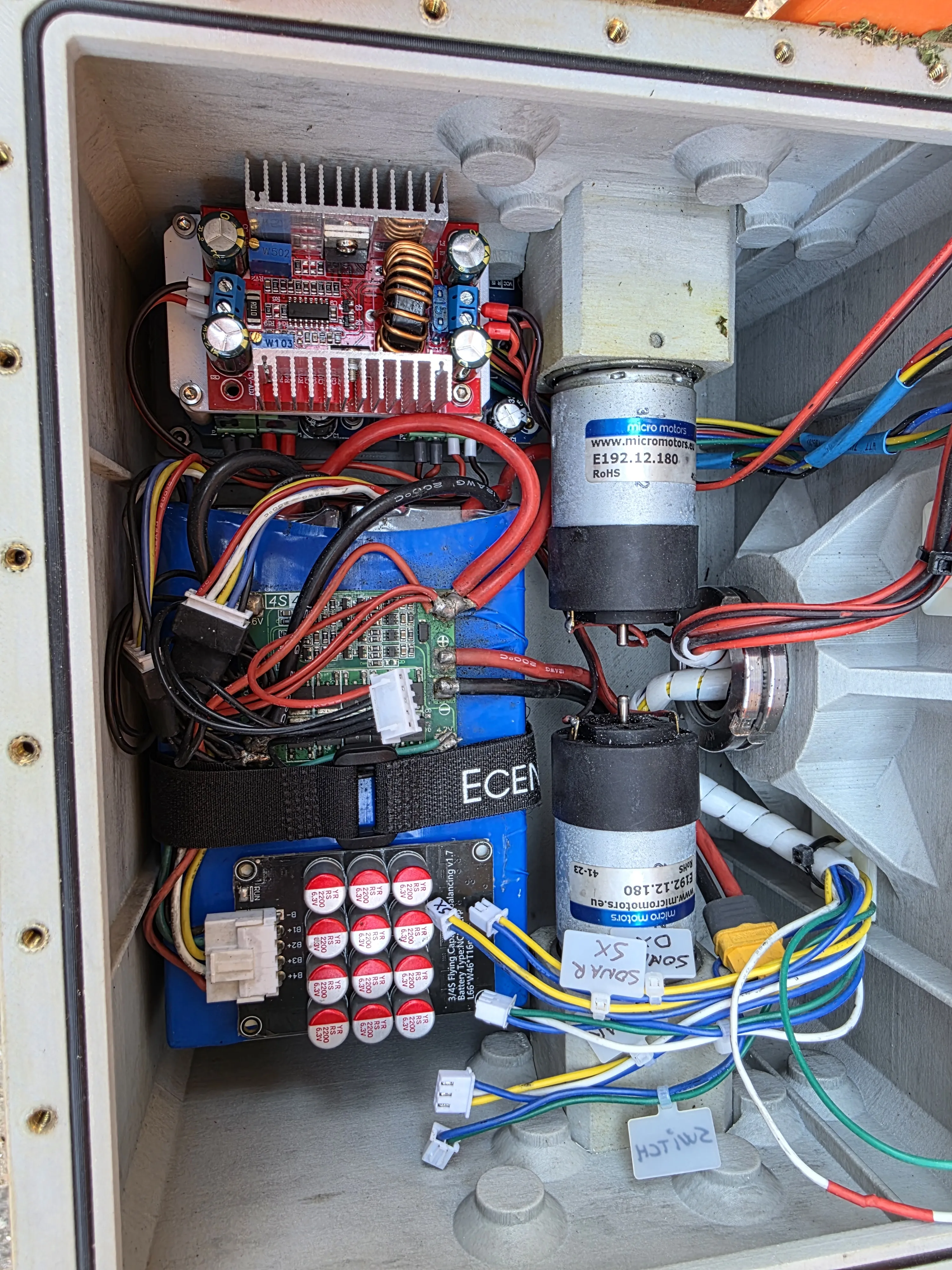
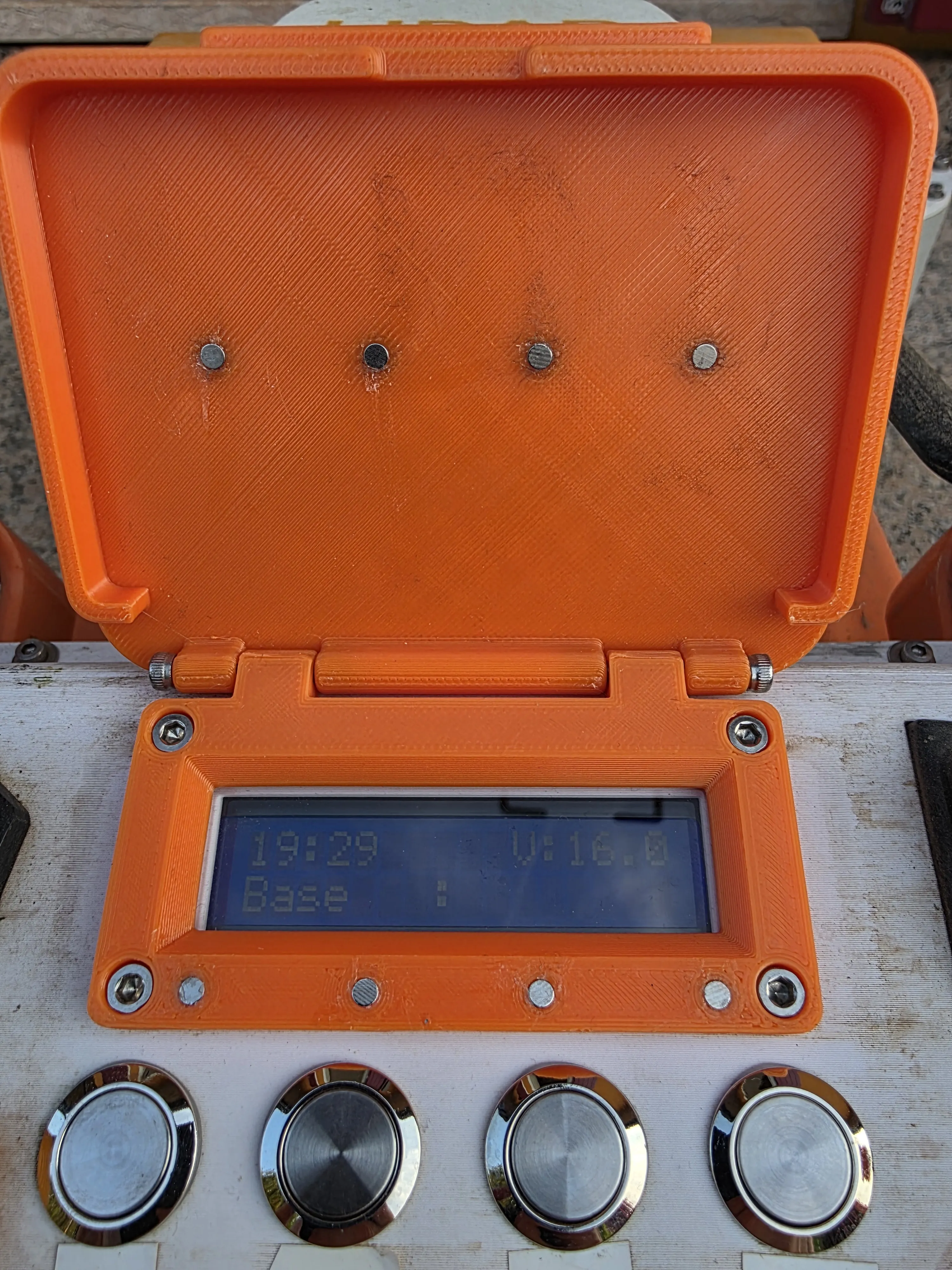
Uploaded the print profile to mount the battery on a support and hold it in place with Velcro straps, and created the display frame with magnetic closure and lettering
Materials
1 Pc Reusable Velcro cable ties
https://www.amazon.it/dp/B07XZG79LZ?ref=ppx_yo2ov_dt_b_fed_asin_title&th=1
2 Pcs M4x10 Stainless steel countersunk screws
8 Pcs Ø3x1 Neodymium magnet
https://www.amazon.it/dp/B0CFV47T49?ref=ppx_yo2ov_dt_b_fed_asin_title
Assembly
To mount the battery support, simply insert the straps into the appropriate slots and place the one near the closed wall with the plastic ring at the top, while securing the other in the slot
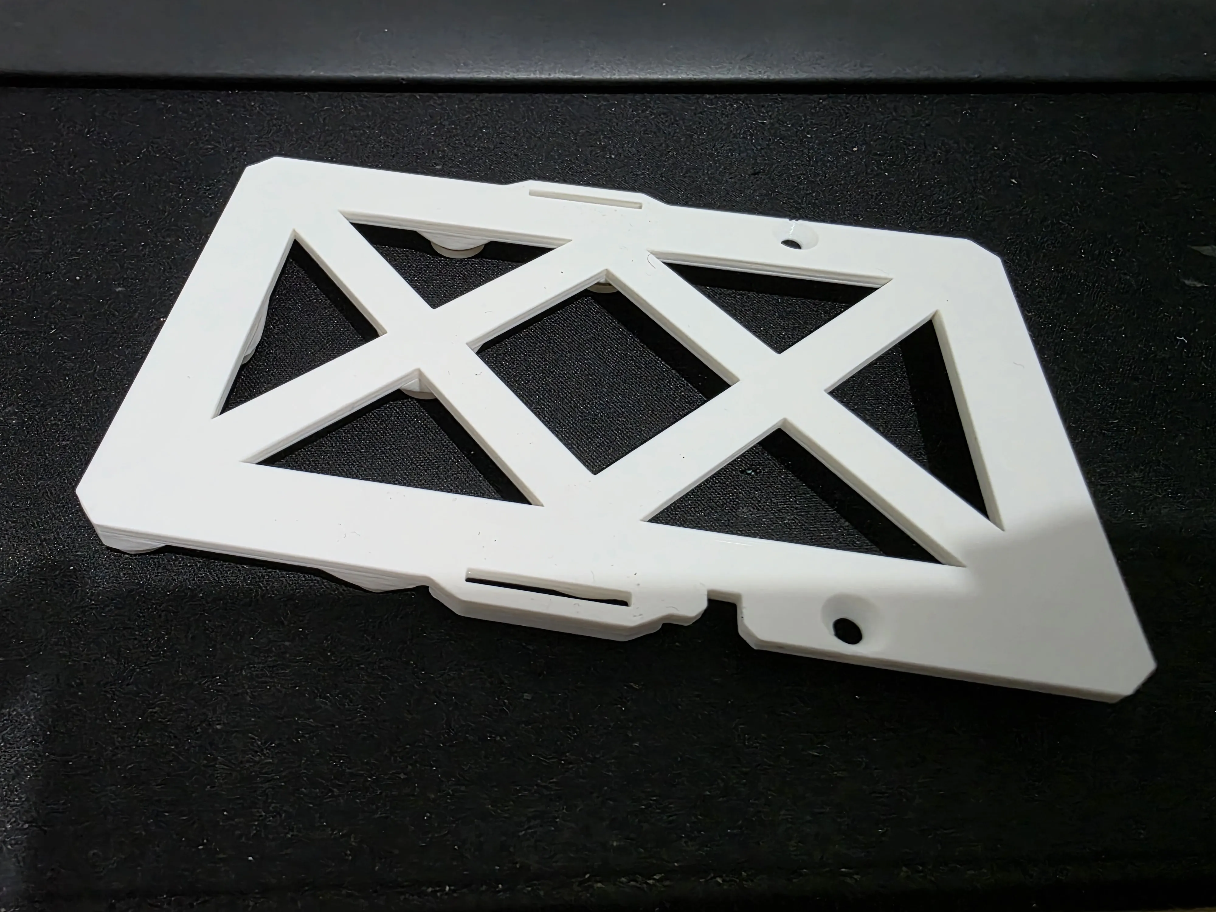
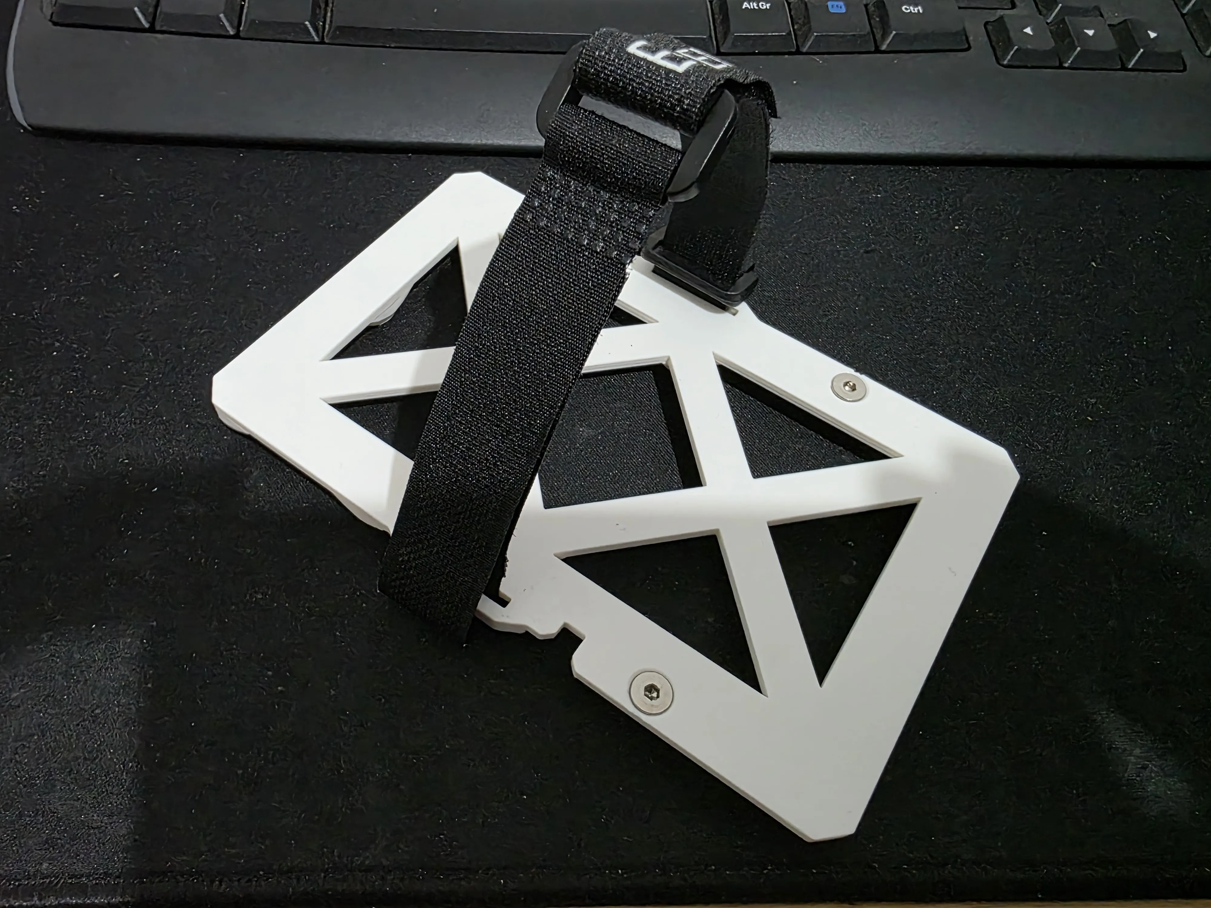
Then, once this is done, screw the support into position
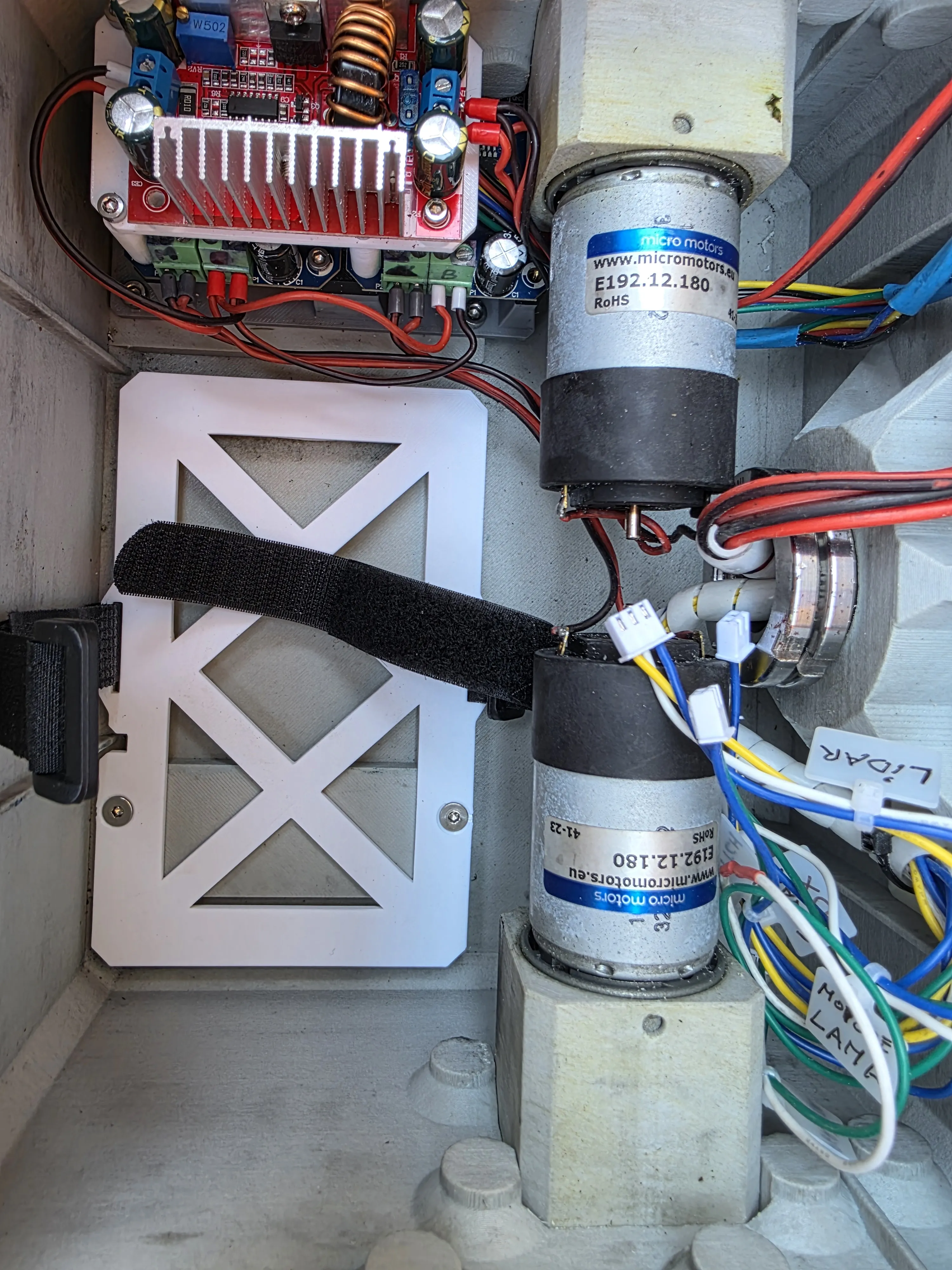
and then insert the battery and secure it with the straps
For the frame, simply glue the magnets into the corresponding holes, being careful not to reverse the polarity, otherwise it will open instead of staying closed Then replace the old type and mount the new one
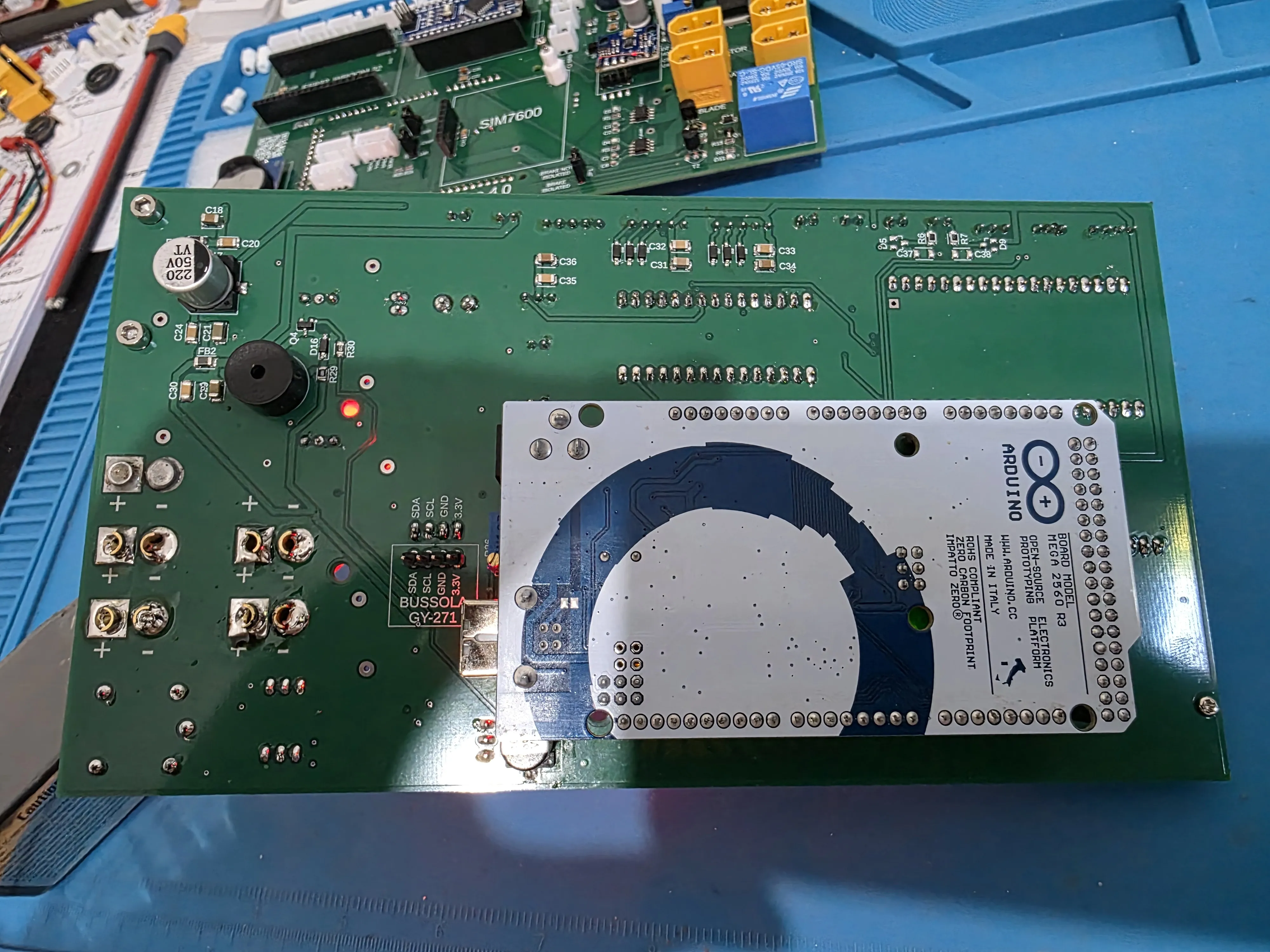
🔧 Project Update – New Integrated PCB and New Home Assistant Card
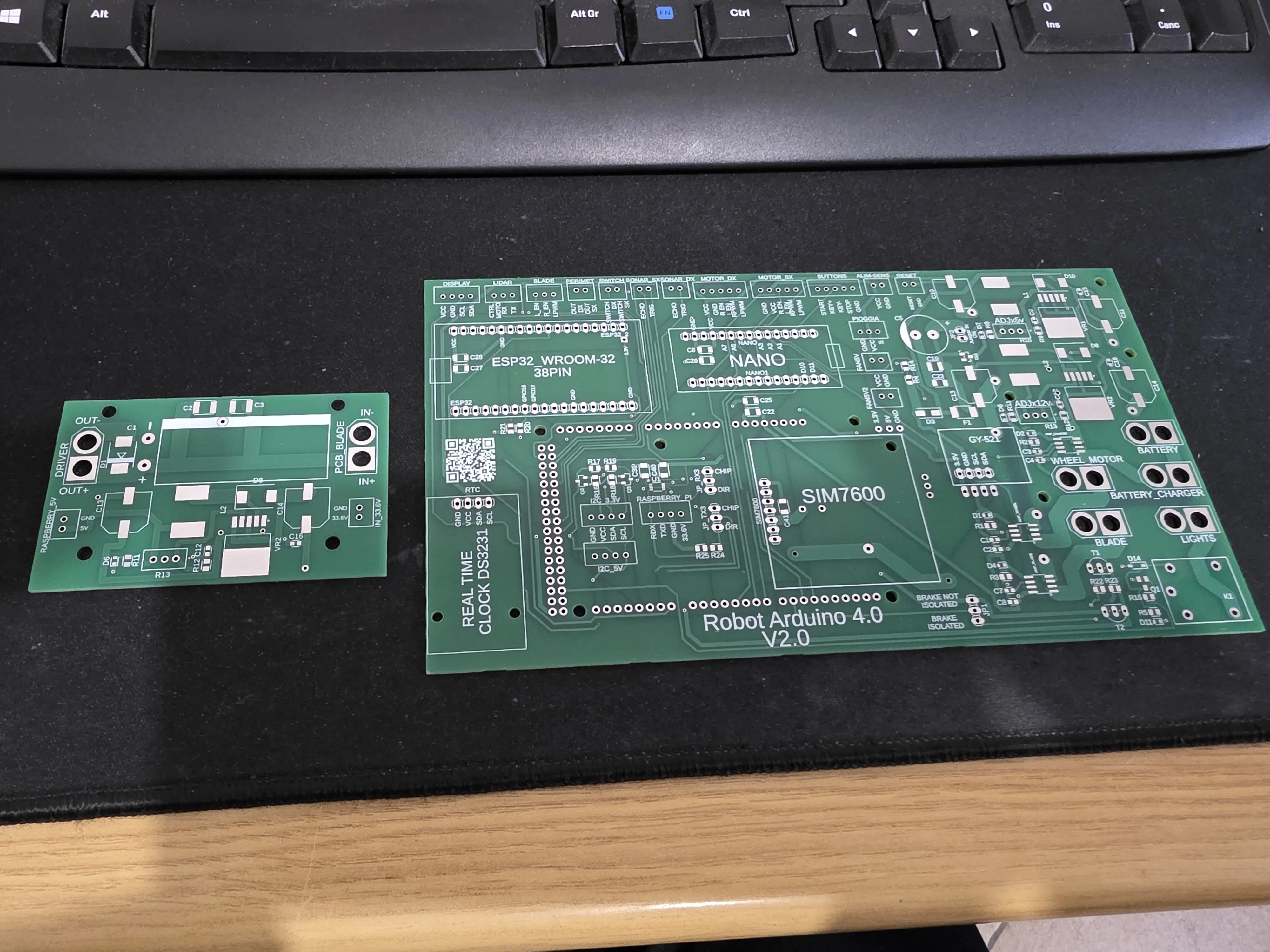
The project continues to evolve, and after many tests and revisions, I have created a new fully integrated PCB for the Arduino robotic lawnmower
This new board has been designed to significantly simplify internal wiring, improve reliability, and make future robot upgrades much easier
Main features of the new PCB:
• ESP32 integrated directly on the board, replacing the previous NodeMCU8266
• WiFi and 3G/4G connection support via SIM7600 module
• OTA firmware update for ESP32
• Several integrated step-downs:
- dedicated 5V power supplies for boards and sensors
- dedicated power supply for the SIM7600 module
- dedicated 12V line for lights
• Filtering and protections on power supply lines
• Support for LiPo batteries up to 8S
• Integrated connections for: - motor drivers
- sensors
- perimeter wire system
- RTC DS3231 clock
- future expansion modules
• Dual I2C port: - one at 5V
- one prepared for 3.3V
• Dedicated UART connection for Raspberry Pi integration
• Optimized layout for a cleaner and more reliable installation
• Specifically designed for future hardware and software upgrades
• PCB supplied fully assembled with soldered SMD components
I have also designed a separate PCB dedicated to:
• blade motor braking management
• Raspberry Pi power supply
• installation inside the robot's central shell
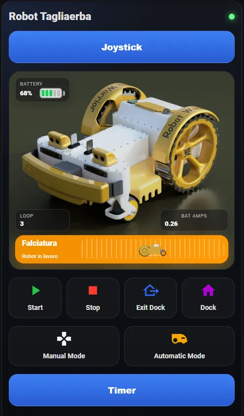
In parallel, I am also developing a new custom card for Home Assistant, specifically designed for the robot and integrated via MQTT
Main features of the card:
• Manual robot control via joystick
• Real-time status display:
- mowing
- parked
- charging
- at base
- wire tracking
• Quick control of main commands: - start
- stop
- dock
- manual/automatic mode
• Battery monitoring with voltage, percentage, and current draw
• Timer management directly from Home Assistant
• OTA firmware update for ESP32 directly from the interface
• Animations and dynamic robot status
• Full integration with MQTT and Home Assistant
• Installation via HACS
All this design, firmware development, electronics, Home Assistant integration, and testing is taking a lot of my time, but the goal is to make the project increasingly stable, expandable, and professional
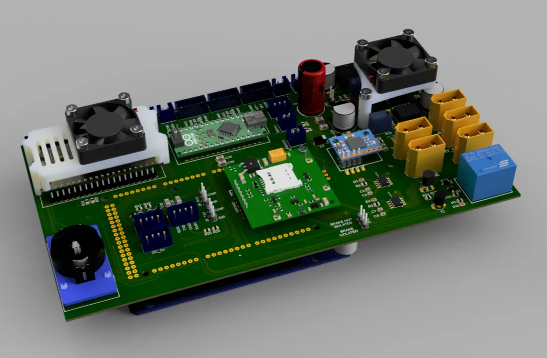
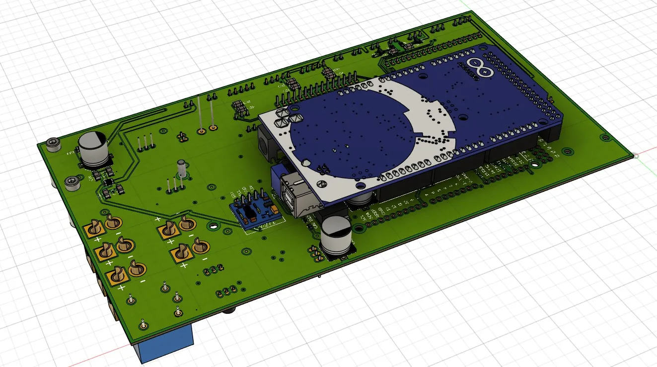
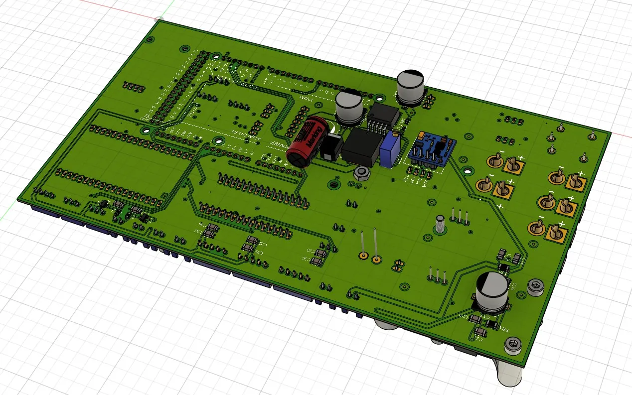
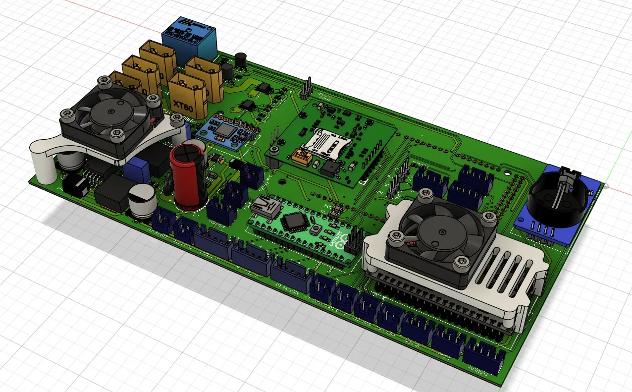
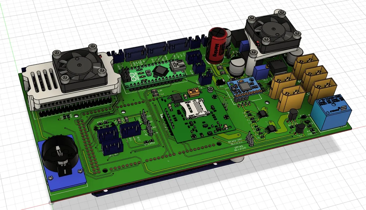
PCBs ready for component soldering
Home Assistant card downloadable from HACS
Update
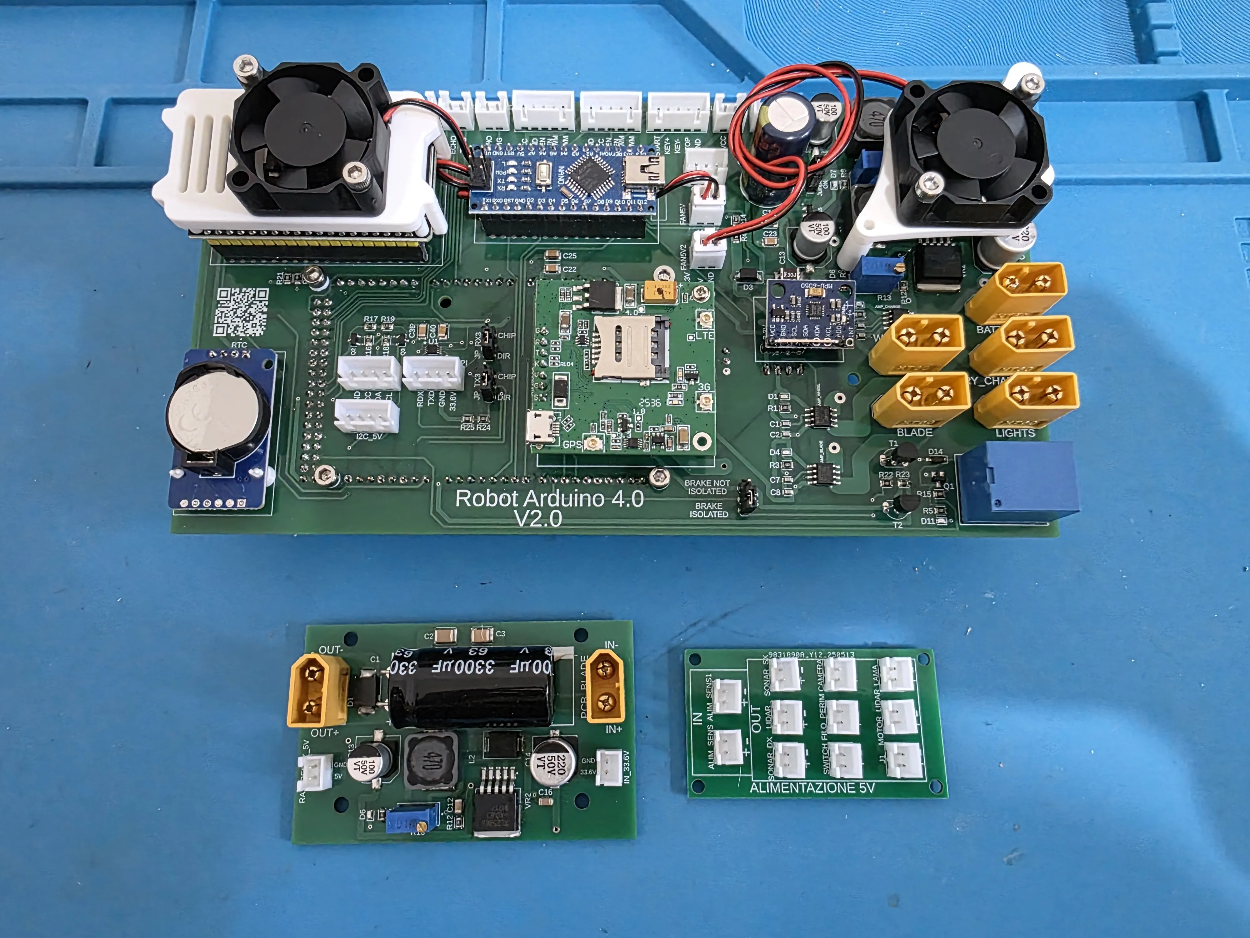
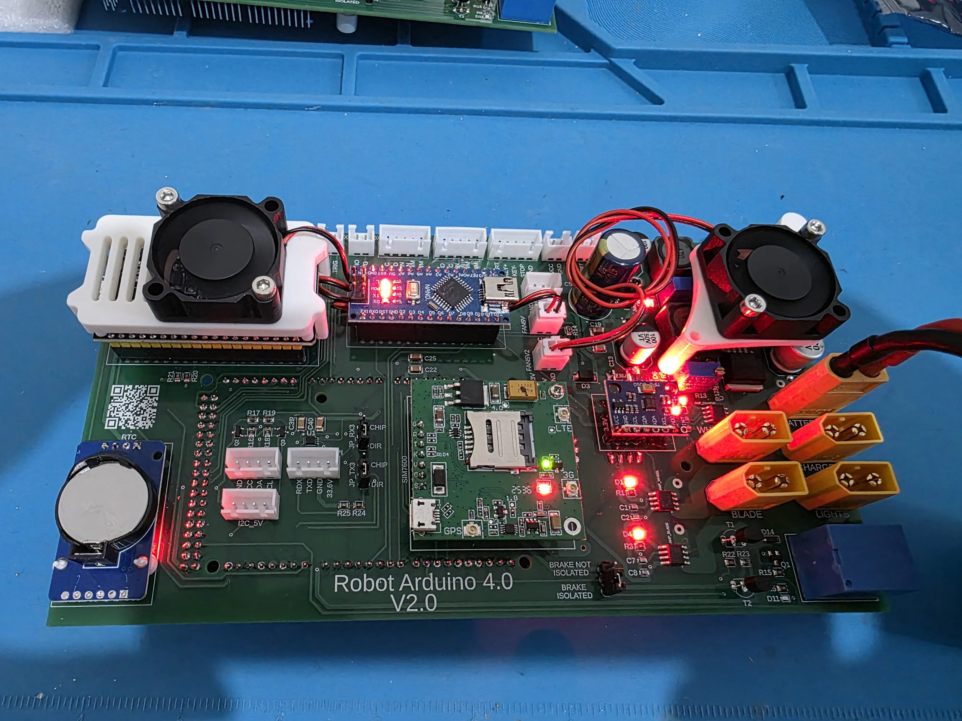
1. Main Motherboard (Arduino Robot 4.0 V2.0)
It is the brain and central data routing hub of the entire lawnmower ecosystem
- Control Architecture: Designed to host the primary calculation logic (managed by an Arduino Mega via serial communication) and intelligent connectivity entrusted to an ESP32 module
- Balanced Active Thermal Management: Features two upper cooling modules dedicated to distinct functions:
- Left Fan: Dedicated to cooling the ESP32, ensuring thermal stability for the microcontroller during high-frequency data exchange and telemetry
- Right Fan: Dedicated to the thermal dissipation of the integrated on-board step-down regulators These modules convert the main voltage to generate the 5V line (board logic power) and the 12V line (power for the lighting system)
- Global Connectivity with Cellular Failover: Integrates a central slot for advanced geolocation (GPS/RTK antenna interface) and hardware predisposition for the SIM7600 (3G/4G LTE) module This module will act as a strategic backup connection for home automation and remote control: if the ESP32 detects the loss of the home Wi-Fi signal while the robot is mowing the lawn, the on-board logic switches the network route to the 4G cellular network This way, the transmission of telemetry data and commands via MQTT to Home Assistant continues without interruption (Note: The hardware section is assembled and ready; software integration into the code will be developed in subsequent phases)
- Power and Signal Interfaces: On the right are the high-current XT60 connectors dedicated to the main outputs, clearly silk-screened: BAT (Battery), BLADE (Blade Motor), and LIGHTS (Navigation Lights/LEDs) On the left, you can see the housing for the RTC DS3231 module's button battery (to maintain the internal clock) and expansion ports for sensors and I2C buses (5V and 3.3V)
2. Blade Braking Protection and Auxiliary Power Module (Bottom left)
This PCB is divided into two independent functional zones, structured for motor safety and future expansions:
- Blade Driver Protection Zone (Braking): Manages electrical safety during rapid blade shutdown When the motor brakes, it acts as a generator, sending back strong voltage spikes (back electromotive force) This zone, supported by the 3300 µF / 63V capacitor, absorbs and cuts these spikes, preventing them from burning the blade driver or damaging the logic electronics
- Future Hardware Step-Down Zone (Raspberry Pi): Houses a switching converter entirely dedicated to powering a future Raspberry Pi This isolated line ensures that when you decide to implement heavy algorithms (such as artificial vision or advanced mapping), the microcomputer will receive a clean and stable current, without being affected by disturbances generated by the traction and cutting motors
3. Sensor Distribution Board "5V Power Supply" (Bottom right)
It is the strategic satellite module positioned beyond the chassis joint, optimized for the robot's mechanical architecture
- Clean Distribution Hub: Groups and distributes 5V lines to all on-board sensors (Sonar, Lidar, Perimeter Wire module, and chassis safety switch)
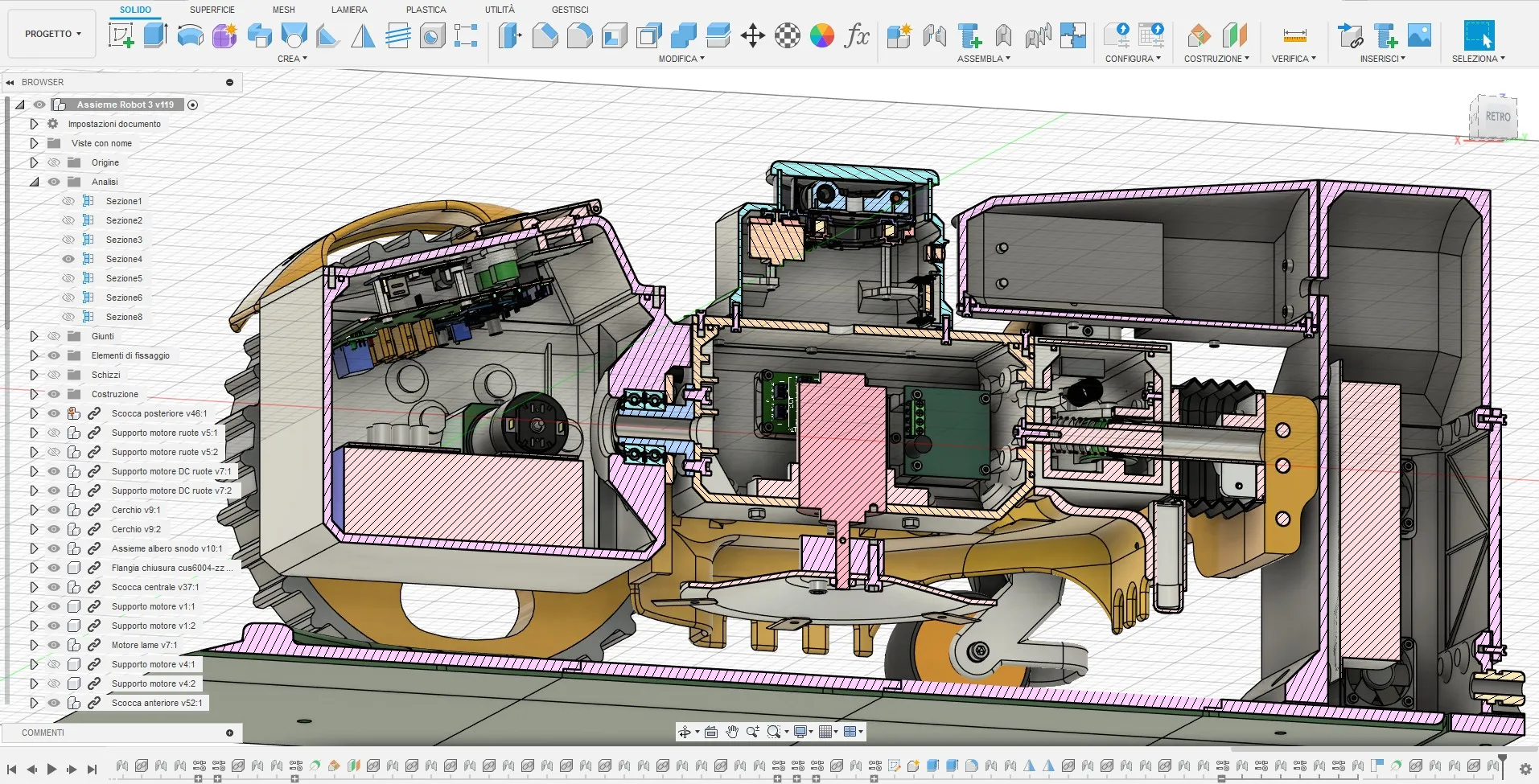
- Anti-Tangle Solution for Articulated Chassis: Its crucial function is logistical Since the robot is divided into two articulated parts, this board centralizes sensor connections at a single point This way, it avoids having to route dozens of individual cables through the central hole of the mechanical joint's shaft, drastically reducing the risk of wear, mechanical stress, wire twisting, or false contacts during the robot's movements on the ground
Documentation (12)
License

You shall not share, sub-license, sell, rent, host, transfer, or distribute in any way the digital or 3D printed versions of this object, nor any other derivative work of this object in its digital or physical format (including - but not limited to - remixes of this object, and hosting on other digital platforms). The objects may not be used without permission in any way whatsoever in which you charge money, or collect fees.


Comment & Rating (152)