Arduino robotic lawnmower charging base


Print Profile(3)

Description
Model
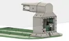
Here is the charging base for the Arduino Lawn Mower Robot which contains the perimeter wire electronics. There are no external openings to prevent the boards from oxidizing, and because 220V is inside. It is better that everything is sealed to avoid any kind of problems
At this link you will find the codes for the various robot boards, the perimeter wire, and the libraries to make everything work
https://github.com/Marcobedendo78/Robot-Arduino-4.0
Here you will find the printable parts of the Arduino lawn mower robot
https://makerworld.com/en/models/420276#profileId-323001
Boost Me (for free)
Give me a boost if you like my Lawn Mower Robot
Printed Parts
The upper part of the base is printed in ASA to be weather resistant, while the green base is printed in ABS to avoid warping problems
All 12 parts of the base are interlocked, while the four holes on the sides are used to fix the base to the ground with stakes
The ASA part is the one that contains all the electronics for the perimeter wire and is composed of 3 pieces to be screwed together and sealed with the TPU gaskets to be printed
Parts to insert
In the various pieces there are several blind holes where M3-M4-M5 threaded brass inserts are to be inserted so that the screws can be tightened without stripping the plastic
Stainless Steel Screws
For the covers I used Pcs26 M3x10 recessed Allen screws
For the boards Pcs14 M3x6
For the fans and supports Pcs12 M3x16
For the power supply Pcs4 M4x6
To connect the tip base to the top Pcs4 M4x10 are needed
To fix the top part with the part containing the electronics Pcs4 M5x16 are needed
To fix the vertical column to the base Pcs10 M5x20 are needed
Fixing stainless steel tips Pcs4 M5x16
Stainless Steel Tips
For the charging tips, two pieces of 100x30 1mm thick stainless steel flat bar are sufficient, which must be drilled and bent so that they touch the robot's two plates. Also 70x25 3mm thick stainless steel ones. The blades must be tight but not excessively so, otherwise the robot will have difficulty inserting itself all the way
Electronic Parts
Arduino UNO Pcs1
Buck Converter LM2596 DC-DC step down Pcs2
L298 Driver Pcs2
MEAN WELL WATERPROOF IP67 XLG SERIES 150 W 24V POWER SUPPLY WITH PFC Constant Voltage or Current AC 220V to DC 24V CC and CV MODE Transformer Model (XLG-150-24-A 150 WATT) Pcs1
Fan 40x40x10 24V Pcs2
Cable for charging tips 16awg
Tinned wire Ø3mm for perimeter wire
Cable gland PG9 Pcs1
Tips
If you want to avoid problems with the wire signal, there must be more than 20m of wire creating the perimeter. The L298 drivers should be placed in parallel with each other, and at each individual bridge, the outputs should be connected together. This is because each output of an L298 driver can deliver a maximum of 2A. By connecting 2 outputs of a driver in parallel, you get 4A, and by putting 2 drivers in parallel, you get 8A. This way, they are less stressed, especially if you have about 250m of cable laid out
The voltage to be regulated on the LM2596 DC-DC ranges from a minimum of 6.5V to a maximum of 14V. Mine is regulated at 13.3V with 220m of wire. The 5V to power Arduino UNO is provided by the L298 driver. For those who wish, they can use the second LM2596 DC-DC (there is space for it) regulated to 5V to power Arduino UNO without using the 5V from the L298 drivers
At the bottom of the base, there are grooves for inserting the perimeter wire, both incoming and outgoing, and for entering through the hole in the base
PS: I recommend siliconizing the hole where the perimeter wire enters once you are sure not to move the base from its positioned spot
I also recommend leaving a linear section at the entrance of the base of at least 1.5m to allow the robot to perform its exit and re-entry maneuvers
Free project:
This robot is a completely free project in which I have invested a lot of time and effort. I don't charge anything for it, wanting to share it with other technology and robotics enthusiasts
It's free, but if you feel the need to support me, you can offer any amount you wish. Thank you
https://www.paypal.com/pool/9blLX2JvUL?sr=wccr
Update
I have added the print profile for the central column and a new support for the perimeter wire driver and its step-down
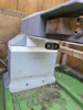
Now you can insert a 36v power supply using an existing hole and a new one on the bottom left. See photo

The only thing is that to use the M4 screw, you need to slightly enlarge the power supply's screw hole by 1mm
On the right, you can mount the support for the new BTS7960 driver and its step-down to power it. This should be regulated to 24v and maximum amperage, and the output connected to the BTS7960's power input. This is because the driver does not support the 36v of the new power supply but a maximum of 27v
A 40x40x10 24v fan can be mounted on the driver support, which uses the same power supply as the driver
This modification is necessary to charge the robot if you upgrade to the latest version, which involves powering the robot via an 8s Lipo and using the new driver for the perimeter wire signal
The new driver is much more powerful than the old L298s and supports a longer perimeter cable length. Currently, I have laid about 250m of cable and it doesn't cause any problems, whereas with the L298s they were at their limit and heated up a lot with the risk of burning out
To connect the perimeter wire to the new driver, it doesn't change much; just connect it to M+ and M- while the power supply to B+ and B-
If the robot sees the perimeter wire reversed, simply reverse the perimeter wire cables (M+ with M-). Make sure not to reverse the power cables (B+ B-) otherwise you will burn out the driver

All remaining parts remain unchanged
Parts needed for the modification:
Pcs 1 Mean Well LRS-150-36 https://it.aliexpress.com/item/1005007455979760.html?spm=a2g0o.order_list.order_list_main.47.2f7436966Xjeb1&gatewayAdapt=glo2ita
Pcs 1 300W XL4016 DC-DC Max 9A Buck Converter Step Down https://it.aliexpress.com/item/1005006097874013.html?spm=a2g0o.order_list.order_list_main.41.2f7436966Xjeb1&gatewayAdapt=glo2ita
Update
I have added the print profile for the part that prevents the robot from compressing the bumper when entering the charging base, which would cause incorrect docking of the robot. To avoid printing a new cover, I drilled the old one and glued the new part onto the cover. I still secured everything with screws to make it more solid. Then, M4 threaded inserts are to be inserted into the front holes, where the TPU stop, which the robot touches when it enters the base, is then screwed in
All remaining parts remain unchanged

Parts needed for the modification:
Parts to insert
In the TPU stop support, M4 threaded brass inserts are to be inserted so that the screws can be tightened without stripping the plastic
Stainless Steel Screws
For the TPU stop support, I used Pcs4 M3x15 recessed Allen screws
M4 Nut Pcs4
For the TPU stop M4x15 Allen screws
Documentation (4)


License
You shall not share, sub-license, sell, rent, host, transfer, or distribute in any way the digital or 3D printed versions of this object, nor any other derivative work of this object in its digital or physical format (including - but not limited to - remixes of this object, and hosting on other digital platforms). The objects may not be used without permission in any way whatsoever in which you charge money, or collect fees.
Comment & Rating (13)