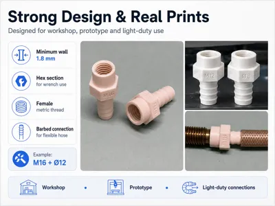
Parametric Auto-Labeled Female METRIC Hose Adapter


Print Profile(1)

Description
Boost Me (for free)
If this model is useful for your workshop, prototypes, hose routing or custom threaded connections, a Boost would be greatly appreciated.
It helps me keep developing practical, tested and fully parametric functional parts.
Description
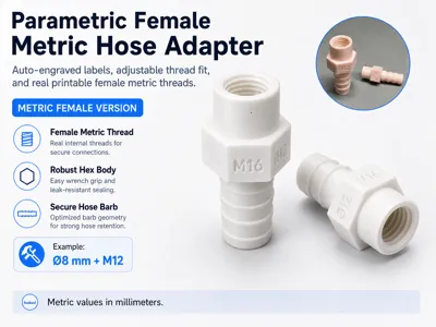
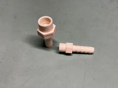
This is a fully parametric straight barbed hose-to-female-thread adapter with:
- adjustable female thread fitting clearance
- automatic engraved size identification
- automatic structural protection
- real printable ISO metric thread geometry
Unlike fixed-tolerance models, this adapter includes a dedicated FIT_OFFSET parameter that allows the female thread clearance to be adjusted directly in OpenSCAD / MakerWorld Customizer.
This makes it possible to compensate for:
- printer dimensional accuracy
- extrusion calibration
- filament shrinkage
- layer height
- material type
- mating male thread tolerance
- the preferred tight or free-running fit
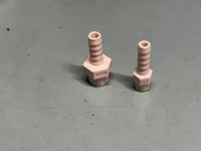
Each generated fitting automatically includes:
- the selected metric female thread engraved on one hex face, for example M20
- the selected hose internal diameter engraved on an adjacent face, for example Ø12
- a user-adjustable female thread fitting allowance
- a continuous internal passage
- automatic minimum wall protection
The labels update automatically whenever the Customizer parameters are changed.
This makes every printed fitting immediately identifiable and allows the threaded fit to be tuned without manually editing the model or relying only on slicer compensation.
There is no need to:
- manually add text
- rename the model
- remodel the thread
- calculate the thread pitch
- manually resize the internal thread
- measure the fitting after printing
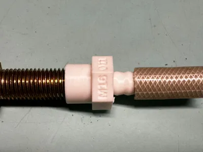
The model is designed to connect a flexible rubber, silicone or soft PVC hose to a male metric threaded component.
It combines five main functional features:
- a parametric barbed hose connection
- a metric hexagonal wrench section
- an internal ISO metric female thread
- adjustable female thread fitting clearance
- automatic engraved size identification
This is the Metric Female Thread Version of the model.
All editable dimensions and fitting corrections are expressed in millimeters.
The model can be customized directly in OpenSCAD / MakerWorld Customizer by changing only seven essential user parameters.
The remaining technical dimensions are calculated automatically, including:
- barb diameter
- barb height
- number of barbs
- barb spacing
- thread pitch
- thread length
- effective female thread clearance
- internal passage
- minimum wall thickness
- minimum threaded sleeve diameter
- minimum hexagonal size
- engraved thread label
- engraved hose diameter label
The complete adapter maintains a minimum radial wall thickness of 1.8 mm beneath the barb roots, around the female thread and across the hexagonal faces.
If the selected dimensions or fitting allowance require a larger external body, the generator automatically adjusts the threaded sleeve and hexagonal section to preserve the required structural thickness.
Main Unique Features
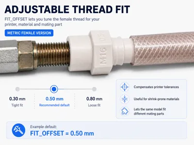
Adjustable Female Thread Fit
The female thread includes a dedicated:
FIT_OFFSET
parameter.
FIT_OFFSET controls the total diametral clearance added to the internal female thread.
This allows the printed thread to be adapted to:
- different printers
- different materials
- different nozzle calibrations
- different layer heights
- different mating components
- different preferred assembly clearances
Recommended starting values:
| FIT_OFFSET | Expected result |
|---|---|
| 0.30 mm | Precise fit for a well-calibrated printer |
| 0.50 mm | Recommended general-purpose default |
| 0.60–0.70 mm | Freer fit for shrink-prone materials or slight overextrusion |
| 0.80–1.00 mm | Intentionally loose and highly permissive fit |
Increasing FIT_OFFSET enlarges the female thread clearance without changing:
- nominal thread size
- metric thread designation
- thread pitch
- engraved label
- hose dimensions
- structural wall logic
Example:
An M20 thread remains an M20 thread.
FIT_OFFSET only changes the printable clearance around the mating male thread.
This feature is especially useful when printing with:
- ASA
- ABS
- PA / Nylon
- PA-CF
- materials with significant shrinkage
- printers that produce slightly undersized internal features
- mating components with rough or coated threads
The same model can therefore be calibrated independently for different printers and materials.
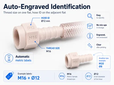
Automatic Engraved Identification
The metric female thread and hose size are automatically engraved on two adjacent flat faces of the hexagonal body.
Example:
M20 Ø12
This identifies the fitting as:
- M20 internal female metric thread
- 12 mm nominal hose internal diameter
The text is:
- generated automatically
- centered on the hexagonal faces
- correctly oriented
- engraved rather than embossed
- updated with every parameter change
- permanently visible after printing
The engraving depth is approximately:
0.45 mm
This provides clear identification without significantly weakening the hexagonal body.
FIT_OFFSET is not engraved because it is a printer-calibration value rather than a nominal fitting size.
The identification feature is especially useful for:
- workshop storage
- sets of similar fittings
- prototype testing
- maintenance kits
- organized parts drawers
- repeated production
- identifying fittings after use
- separating similar metric thread sizes
- avoiding repeated measurements
Intended Applications
The model is intended for light-duty workshop, DIY, maker, hobby and prototype applications such as:
- flexible rubber hose connections
- silicone tube connections
- soft PVC hose adapters
- male threaded workshop accessories
- low-stress drain or vent lines
- custom cooling circuits
- prototype fluid routing
- experimental air routing
- utility hose connections
- custom machine accessories
- non-critical low-pressure connections
- test benches
- temporary workshop setups
- custom metric threaded fittings
The barbs are automatically generated according to:
- hose internal diameter
- available insertion length
- selected grip level
- minimum structural wall thickness
The internal thread uses an automatically selected ISO metric coarse pitch according to the chosen nominal thread diameter.
The female thread also includes:
- adjustable printable clearance
- controlled thread entry chamfer
- clean continuous helical geometry
- automatic outer sleeve sizing
Part of the CiCadesign Parametric Hose Connector System
This model is part of a growing collection of functional and customizable hose, tube and threaded adapters designed for:
- workshop use
- DIY applications
- prototyping
- light-duty fluid routing
- experimental setups
- machine accessories
- functional FDM printing
Other connector variants are available on my profile, including:
- straight barbed adapters
- angled adapters
- T connectors
- Y connectors
- smooth sleeve connectors
- reducing adapters
- Metric versions
- Inch Preset versions
- male threaded hose adapters
- female threaded hose adapters
Main Features
- Fully parametric straight hose-to-thread adapter
- Adjustable female thread fitting clearance
- Dedicated FIT_OFFSET parameter
- Thread fit adaptable to printer and material
- Recommended 0.50 mm general-purpose allowance
- Automatic engraved size identification
- Metric thread engraved on one hex face
- Hose internal diameter engraved on an adjacent face
- Labels automatically updated by the Customizer
- Metric female-thread version
- All editable dimensions expressed in millimeters
- Barbed connection for flexible hoses
- Internal female metric thread
- Automatic ISO metric coarse pitch
- Controlled printable thread clearance
- Thread entry chamfer
- Metric hexagonal wrench section
- Adjustable wrench size across flats
- Adjustable hexagonal section length
- Adjustable hose insertion length
- Automatic barb number calculation
- Automatic barb geometry scaling
- Adjustable grip level
- Continuous internal through-hole
- Minimum radial wall of 1.8 mm
- Automatic minimum wall protection
- Automatic threaded sleeve sizing
- Automatic minimum hexagon size control
- Compact straight geometry
- Real printable helical thread
- Clean manifold thread geometry
- No external OpenSCAD libraries required
- Printable on standard FDM printers
- Designed for workshop and prototype use
- Suitable for strong high-wall-count profiles
Editable Parameters
The Customizer exposes only the essential parameters.
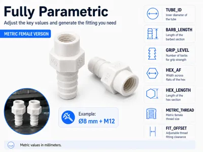
| Parameter | Description |
|---|---|
| TUBE_ID | Nominal internal diameter of the flexible hose |
| BARB_LENGTH | Total length of the barbed hose section |
| GRIP_LEVEL | Barb aggressiveness and hose retention level |
| HEX_AF | Hexagon wrench size measured across opposite flats |
| HEX_LENGTH | Axial length of the hexagonal section |
| METRIC_THREAD | Nominal diameter of the internal female metric thread |
| FIT_OFFSET | Total diametral clearance added to the female thread |
All other technical dimensions and engraved labels are calculated automatically.
Suggested Parameter Ranges
| Parameter | Suggested range | Recommended default | Step |
|---|---|---|---|
| TUBE_ID | 7–40 mm | 12 mm | 0.5 mm |
| BARB_LENGTH | 8–80 mm | 28 mm | 1 mm |
| GRIP_LEVEL | 1–5 | 3 | 1 |
| HEX_AF | 8–60 mm | 24 mm | 1 mm |
| HEX_LENGTH | 4–30 mm | 10 mm | 1 mm |
| METRIC_THREAD | M6–M48 | M20 | Standard sizes |
| FIT_OFFSET | 0.10–1.00 mm | 0.50 mm | 0.05 mm |
Recommended standard metric thread sizes include:
M6 M8 M10 M12 M14 M16 M18 M20 M22 M24 M27 M30 M33 M36 M39 M42 M45 M48
Parameter Meaning
TUBE_ID
TUBE_ID controls the nominal internal diameter of the flexible hose.
Measure the hose internally without compressing it and enter the measured value.
| Hose internal diameter | Suggested TUBE_ID |
|---|---|
| 7 mm | 7 mm |
| 8 mm | 8 mm |
| 10 mm | 10 mm |
| 12 mm | 12 mm |
| 16 mm | 16 mm |
| 20 mm | 20 mm |
| 25 mm | 25 mm |
| 32 mm | 32 mm |
| 40 mm | 40 mm |
The selected value is also engraved automatically on one face of the hexagonal body.
Example:
TUBE_ID = 12
generates the engraved label:
Ø12
The model automatically adds a controlled fitting allowance according to the selected GRIP_LEVEL.
The retaining barb crests are slightly larger than the nominal hose internal diameter, while the barb root and body remain referenced to the selected TUBE_ID.
The generator guarantees at least 1.8 mm of radial wall thickness beneath the barb roots.
For very rigid hoses, use a lower grip level.
For soft rubber or silicone hoses, a higher grip level can provide stronger retention.
BARB_LENGTH
BARB_LENGTH controls the total axial length of the barbed hose section.
A longer barbed section provides:
- more hose contact area
- more retaining barbs
- stronger mechanical retention
- better resistance to hose removal
- more space for a hose clamp
A shorter barbed section provides:
- a more compact fitting
- faster printing
- lower material consumption
- easier installation in restricted spaces
Recommended starting values:
| Hose ID | Suggested BARB_LENGTH |
|---|---|
| 7–8 mm | 15–22 mm |
| 10 mm | 18–25 mm |
| 12–16 mm | 25–32 mm |
| 20–25 mm | 30–42 mm |
| 32–40 mm | 40–60 mm |
The number of barbs is generated automatically from the available length.
GRIP_LEVEL
GRIP_LEVEL controls the interference and aggressiveness of the barb geometry.
| Grip level | Recommended use |
|---|---|
| 1 | Light grip and easy hose removal |
| 2 | Soft grip for harder hoses |
| 3 | General-purpose starting value |
| 4 | Strong grip for flexible rubber or silicone |
| 5 | Maximum retention for very soft hoses |
Recommended starting value:
GRIP_LEVEL = 3
Higher grip levels increase:
- barb height
- hose interference
- mechanical retention
- resistance to accidental removal
Lower grip levels are more suitable for:
- rigid tubing
- harder PVC hoses
- repeated assembly and removal
- delicate or thin-wall hoses
A hose clamp is still recommended whenever secure retention is required.
The minimum 1.8 mm structural wall is maintained independently of the selected grip level.
HEX_AF
HEX_AF controls the wrench size of the hexagonal transition.
The value is measured across opposite flat faces, exactly like a standard metric nut or bolt head.
The generator automatically prevents the hexagonal section from becoming smaller than the minimum size required around:
- the barb section
- the internal passage
- the female thread
- the outer threaded sleeve
- the engraved labels
A minimum radial thickness of 1.8 mm is maintained across the flat faces and around the female thread.
If the selected HEX_AF is too small, the effective hexagonal size is increased automatically.
For easy assembly, select a wrench size large enough to surround the female threaded sleeve and provide good wrench engagement.
Practical starting values:
| Female thread | Suggested HEX_AF |
|---|---|
| M8 | 15–17 mm |
| M10 | 17–19 mm |
| M12 | 19–22 mm |
| M14 | 22–24 mm |
| M16 | 24–27 mm |
| M18 | 27–30 mm |
| M20 | 30–32 mm |
| M24 | 36–41 mm |
| M30 | 46–50 mm |
These are practical printed fitting suggestions and do not necessarily reproduce the standard wrench size of a commercial fitting.
HEX_LENGTH
HEX_LENGTH controls the axial length of the hexagonal wrench section.
It also determines the vertical space available for the automatic engraved labels.
A longer hexagonal section provides:
- better wrench engagement
- larger and clearer engraved labels
- more structural material
- improved resistance during tightening
- more separation between the hose and threaded component
A shorter hexagonal section provides:
- a more compact fitting
- reduced material use
- shorter total adapter length
Recommended values:
| Adapter size | Suggested HEX_LENGTH |
|---|---|
| Small fittings | 5–8 mm |
| General-purpose fittings | 8–12 mm |
| Medium fittings | 10–16 mm |
| Large fittings | 14–22 mm |
Recommended starting value:
HEX_LENGTH = 10 mm
Avoid using an excessively short hexagonal section, especially when:
- the fitting will be tightened with a wrench
- clear engraved identification is required
- the adapter has a large female thread size
METRIC_THREAD
METRIC_THREAD controls the nominal major diameter of the internal female metric thread.
| Parameter value | Generated thread | Engraved label |
|---|---|---|
| 6 | M6 female | M6 |
| 8 | M8 female | M8 |
| 10 | M10 female | M10 |
| 12 | M12 female | M12 |
| 16 | M16 female | M16 |
| 20 | M20 female | M20 |
| 24 | M24 female | M24 |
| 30 | M30 female | M30 |
| 36 | M36 female | M36 |
| 48 | M48 female | M48 |
The selected thread designation is engraved automatically on one hexagonal face.
The ISO metric coarse pitch is selected automatically.
| Thread | Automatic coarse pitch |
|---|---|
| M6 | 1.0 mm |
| M8 | 1.25 mm |
| M10 | 1.5 mm |
| M12 | 1.75 mm |
| M16 | 2.0 mm |
| M20 | 2.5 mm |
| M24 | 3.0 mm |
| M30 | 3.5 mm |
| M36 | 4.0 mm |
| M42 | 4.5 mm |
| M48 | 5.0 mm |
The female thread length is derived automatically from the selected metric size.
The thread is generated as real printable helical geometry and does not require an external OpenSCAD thread library.
FIT_OFFSET
FIT_OFFSET controls the total diametral fitting allowance applied to the internal female thread.
Example:
FIT_OFFSET = 0.50 mm
adds approximately:
0.25 mm of radial clearance per side
The value does not change the nominal thread designation.
For example, an M20 thread remains identified and engraved as:
M20
FIT_OFFSET only compensates the printable internal geometry.
Use a smaller value when:
- the printer is dimensionally accurate
- the filament has low shrinkage
- a tighter thread fit is preferred
- the mating component is slightly undersized
Use a larger value when:
- the printed thread is too tight
- the material shrinks significantly
- the printer produces undersized internal features
- the mating component has a rough or oversized thread
- easier manual assembly is preferred
Recommended starting value:
FIT_OFFSET = 0.50 mm
Before producing a large adapter, print a short thread test and adjust FIT_OFFSET using the same printer, filament and layer settings intended for the final part.
Automatic Minimum Wall Protection
The adapter is designed never to generate less than 1.8 mm of radial wall thickness in the principal structural areas.
The minimum wall is protected:
- beneath the barb roots
- around the internal passage
- outside the female thread major diameter
- across the flat faces of the hexagonal body
- through the transition between sections
When the selected female thread requires a larger external body, the threaded sleeve diameter is enlarged automatically.
When the selected wrench size is too small, the hexagonal body is enlarged automatically.
If the hose bore, thread size and fitting allowance cannot preserve both the internal passage and the minimum structural wall, OpenSCAD stops generation with a clear assertion message instead of creating a fragile or invalid part.
Internal Passage
The model includes a continuous axial through-hole from the hose side to the female threaded side.
The internal passage is calculated from the selected hose diameter and the available thread geometry.
The generator preserves:
- a practical internal bore
- the female thread profile
- the selected FIT_OFFSET
- the minimum 1.8 mm structural wall
For unrestricted flow, choose a female thread sufficiently larger than the required internal passage.
Example:
A 20 mm hose should not be combined with a very small female thread such as M12.
For better flow and stronger walls, select a thread diameter that provides enough material around the internal bore and enough clearance for the male mating part.
Important Size Compatibility Note
The following dimensions must be considered together:
- hose internal diameter
- female metric thread diameter
- internal passage
- FIT_OFFSET
- minimum wall thickness
- outer threaded sleeve diameter
- hexagonal wrench size
- hexagonal label area
A very large hose combined with a very small female thread can create:
- an impossible internal bore
- an automatically enlarged external body
- reduced available flow
- an impractical fitting combination
- an assertion warning if the geometry cannot remain valid
For best results, the female thread should normally be larger than the hose internal diameter.
Suggested combinations:
| TUBE_ID | Suggested female metric threads |
|---|---|
| 7–8 mm | M12 / M14 / M16 |
| 10 mm | M14 / M16 / M18 |
| 12 mm | M16 / M18 / M20 |
| 16 mm | M22 / M24 / M27 |
| 20 mm | M27 / M30 / M33 |
| 25 mm | M33 / M36 / M39 |
| 32 mm | M42 / M45 / M48 |
| 40 mm | Custom size larger than M48 recommended |
These are practical starting points and should be verified according to:
- required internal flow
- mating male thread
- selected FIT_OFFSET
- material
- mechanical load
Example Metric Presets
| Preset | Hose side | Thread side | Automatic labels | Suggested use |
|---|---|---|---|---|
| 8 mm → M14 female | 8 mm hose | M14 female | Ø8 / M14 | Small workshop adapter |
| 10 mm → M16 female | 10 mm hose | M16 female | Ø10 / M16 | Light fluid routing |
| 12 mm → M20 female | 12 mm hose | M20 female | Ø12 / M20 | General-purpose fitting |
| 16 mm → M24 female | 16 mm hose | M24 female | Ø16 / M24 | Medium workshop connection |
| 20 mm → M30 female | 20 mm hose | M30 female | Ø20 / M30 | Cooling or drain prototype |
| 25 mm → M36 female | 25 mm hose | M36 female | Ø25 / M36 | Larger utility fitting |
| 32 mm → M48 female | 32 mm hose | M48 female | Ø32 / M48 | Large light-duty routing |
Recommended naming logic:
Hose ID → Female Metric Thread
Example:
12 mm → M20 female
The generated fitting will automatically show:
Ø12 M20
on the two adjacent hexagonal faces.
Printing Recommendations
Recommended materials:
| Material | Recommendation |
|---|---|
| ASA | Excellent for workshop use, temperature resistance and outdoor exposure |
| PETG | Good general-purpose option |
| PCTG | Good toughness and layer adhesion |
| PA / Nylon | Excellent for strong functional fittings |
| PA-CF | Excellent for rigid and mechanically demanding parts |
| PP | Useful when chemical compatibility and flexibility are required |
| PLA | Only for indoor, cool and very light-duty applications |
Suggested print settings:
| Setting | Recommendation |
|---|---|
| Layer height | 0.12–0.20 mm |
| Thread and label layer height | 0.12–0.16 mm preferred |
| Walls/perimeters | 6–10 |
| Recommended profile | 10 walls for an almost solid part |
| Top/bottom layers | 5–7 |
| Infill | 40–100% |
| Material | ASA, PETG, PCTG, PA or PA-CF |
| Supports | Required with the recommended angled orientation |
| Brim | Recommended for technical materials |
| Seam | Position away from the female thread entrance and engraved labels |
For this type of functional fitting, many walls are more important than a high infill percentage.
A profile using approximately 10 walls/perimeters can make the fitting almost solid, improving:
- female thread strength
- wrench resistance
- hose insertion resistance
- clamp resistance
- durability around the hexagonal transition
- engraved label definition
Use good layer adhesion and properly dried filament, especially with nylon-based materials.
Print Orientation Notes
The recommended orientation is to print the adapter at approximately 60° relative to the build plate, with:
- the barbed section facing downward toward the build plate
- the female threaded section pointing upward
- the adapter body tilted diagonally
- the engraved hex faces positioned away from direct support contact whenever possible
- the female thread entrance kept free from support contact
This orientation generally provides:
- better mechanical strength between the barbed section, hexagonal body and threaded sleeve
- improved layer distribution along the complete adapter
- cleaner internal thread geometry
- better thread roundness
- clearer engraved labels
- reduced risk of weak layer separation at the hexagonal transition
- better overall surface quality
Recommended Support Setup
Use normal snug supports, not organic or tree supports.
Recommended starting values:
Support type: Normal snug
Support placement: Build plate only
Support line distance: 2.5 mm
Top interface layers: 2
Interface pattern: Solid / Dense
Top Z distance from model: 0.10 mm
Raft layers: 2
The support structure should follow the lower side of the tilted adapter closely enough to stabilize the part during printing.
Position the model so that the supports mainly contact:
- the lower side of the barbed section
- the underside of the hexagonal body
- the lower transition areas
Avoid placing direct support contact on:
- the female thread entrance
- the internal thread surfaces
- engraved text
- the main retaining edges of the barbs
After printing, remove the support carefully and lightly clean the supported surfaces if necessary.
A brim is recommended, especially when printing with:
- ASA
- ABS
- PA
- PA-CF
For the best internal thread and label quality:
- use calibrated extrusion flow
- use a layer height between 0.12 and 0.20 mm
- reduce excessive outer-wall speed
- use adequate cooling according to the material
- avoid excessive seam bulging
- place the seam away from the thread entrance and labels
- adjust FIT_OFFSET when necessary
- avoid excessive slicer hole compensation
The female thread entrance may require very light cleaning after printing.
Recommended starting orientation:
45°
Thread Fit and Printer Tolerance
Printed female threads are affected by:
- extrusion width
- layer height
- material shrinkage
- seam position
- printer dimensional accuracy
- elephant foot
- overextrusion
- material type
- mating male thread tolerance
- the selected FIT_OFFSET value
The final thread clearance can be adjusted directly through FIT_OFFSET.
For a tight female thread:
- increase FIT_OFFSET in steps of 0.05–0.10 mm
- check extrusion calibration
- reduce outer-wall flow slightly
- lightly clean the first thread turn
- verify that the mating male thread is truly nominal
For a loose female thread:
- reduce FIT_OFFSET in steps of 0.05–0.10 mm
- verify extrusion calibration
- check the mating male thread
- verify whether the commercial component has a non-standard tolerance
Avoid applying both a large FIT_OFFSET and strong slicer hole compensation unless deliberately required, because the two corrections may accumulate.
Before printing a large fitting, create a short female thread test using:
- the same printer
- the same material
- the same layer height
- the same wall settings
- the selected FIT_OFFSET
- the actual mating component
Do not force the male component into the printed female thread with excessive torque.
Suggested Use
- Measure the internal diameter of the flexible hose.
- Set TUBE_ID to the measured nominal value.
- Choose the required hose insertion length using BARB_LENGTH.
- Start with GRIP_LEVEL = 3.
- Select the required female metric thread.
- Start with FIT_OFFSET = 0.50 mm.
- Choose a suitable wrench size using HEX_AF.
- Set the desired hexagonal section length.
- Generate the model in OpenSCAD or MakerWorld Customizer.
- Verify the automatic engraved labels in the preview.
- Print a short thread test when accurate fitting is important.
- Increase FIT_OFFSET if the thread is too tight.
- Reduce FIT_OFFSET if the thread is too loose.
- Generate and print the final adapter.
- Test the hose fit before installation.
- Test the female thread with the mating male component.
- Use a hose clamp where necessary.
- Use an appropriate gasket, washer, O-ring or sealant where required.
- Check the complete assembly carefully before real use.
Important Safety Notes
This model is intended for non-critical, light-duty, workshop, prototype and hobby use only.
Do not use this printed part for:
- high-pressure systems
- compressed-air safety-critical systems
- fuel lines
- brake lines
- hydraulic systems
- gas installations
- drinking water systems
- food-contact applications
- medical applications
- very hot fluids
- steam
- toxic chemicals
- hazardous chemicals
- structural lifting systems
- applications where failure could cause injury, flooding, fire or serious damage
3D printed parts can fail depending on:
- material
- print orientation
- layer adhesion
- thread quality
- tightening torque
- temperature
- chemical exposure
- pressure
- hose stiffness
- clamp pressure
- UV exposure
- fatigue
- vibration
- long-term creep
Do not apply excessive tightening torque to the printed hexagonal section or force the male component into the female thread.
Use an appropriate gasket, O-ring, sealing washer or thread sealant according to the mating component and intended application.
The printed thread itself does not guarantee a pressure-tight seal.
Always test the adapter carefully before use.
The engraved labels identify the selected nominal dimensions but do not represent pressure, temperature or chemical certification.
The designer is not responsible for misuse, leakage, damage or failure caused by improper application.
Print Profile Note
This is a fully parametric OpenSCAD / MakerWorld Customizer model with:
- adjustable female thread fitting
- automatic engraved size identification
- automatic structural protection
The project is intended to allow users to generate their own:
- hose diameter
- barb length
- grip level
- wrench size
- hexagonal length
- female metric thread
- printable thread clearance
instead of relying only on fixed-size print profiles.
Every generated fitting automatically displays its hose size and female metric thread on the hexagonal body.
For functional parts, I recommend using:
- 6–10 walls
- approximately 10 walls for an almost solid fitting
- good layer bonding
- properly dried filament
- reduced speed around the threaded sleeve
- a fine layer height for better internal thread definition
- careful support placement around the engraved faces and thread entrance
- a FIT_OFFSET calibrated for the selected printer and material
Users should slice the generated version according to:
- printer
- nozzle size
- material
- selected dimensions
- hose stiffness
- mating thread tolerance
- selected FIT_OFFSET
- intended application
Verified community print profiles are welcome and appreciated.
Customizer Note
The parametric model is intended to be edited through OpenSCAD or MakerWorld Customizer using the desktop version.
The exposed user parameters are:
TUBE_ID BARB_LENGTH GRIP_LEVEL HEX_AF HEX_LENGTH METRIC_THREAD FIT_OFFSET
The user selects the required fitting dimensions and the preferred female thread clearance.
The model automatically generates:
- the barb geometry
- the ISO metric coarse female thread
- the user-selected fitting allowance
- the thread entry chamfer
- the continuous internal passage
- the minimum 1.8 mm structural walls
- the required threaded sleeve diameter
- the required hexagonal body size
- the metric thread engraving
- the hose diameter engraving
Bambu Handy is mainly intended for direct printing from ready-made print profiles and may not provide full access to all editable Customizer parameters.
For best results, use OpenSCAD or MakerWorld Customizer from a desktop browser.
License
You shall not share, sub-license, sell, rent, host, transfer, or distribute in any way the digital or 3D printed versions of this object, nor any other derivative work of this object in its digital or physical format (including - but not limited to - remixes of this object, and hosting on other digital platforms). The objects may not be used without permission in any way whatsoever in which you charge money, or collect fees.
Comment & Rating (0)