
Ducati Multistrada V4 GPS mount
Print Profile(2)
Description
IMPORTANT NOTE
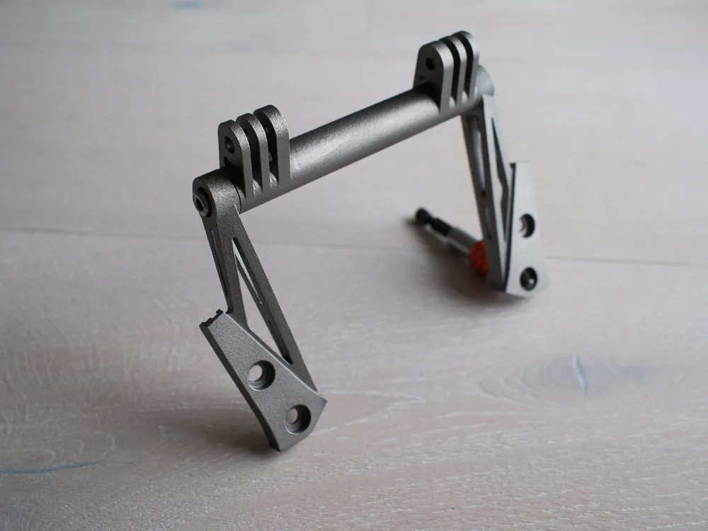
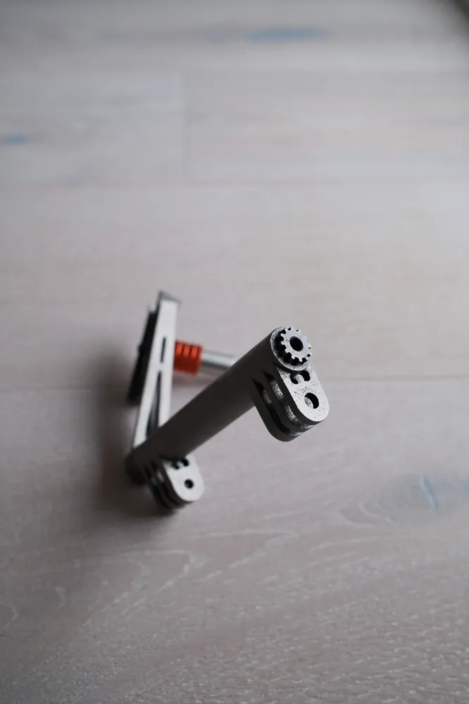
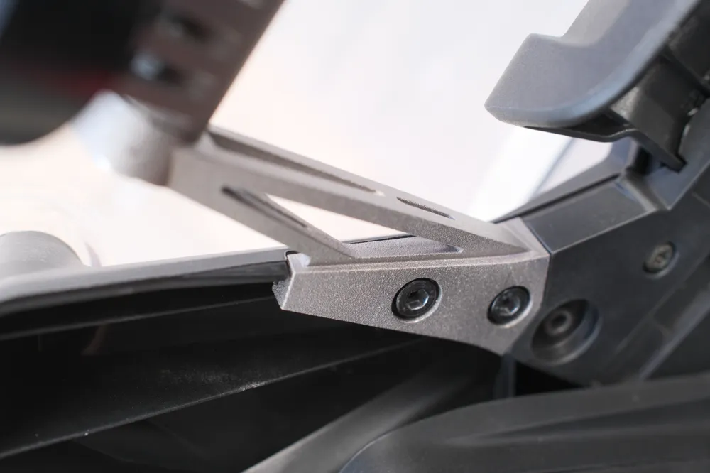
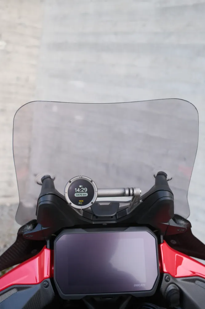
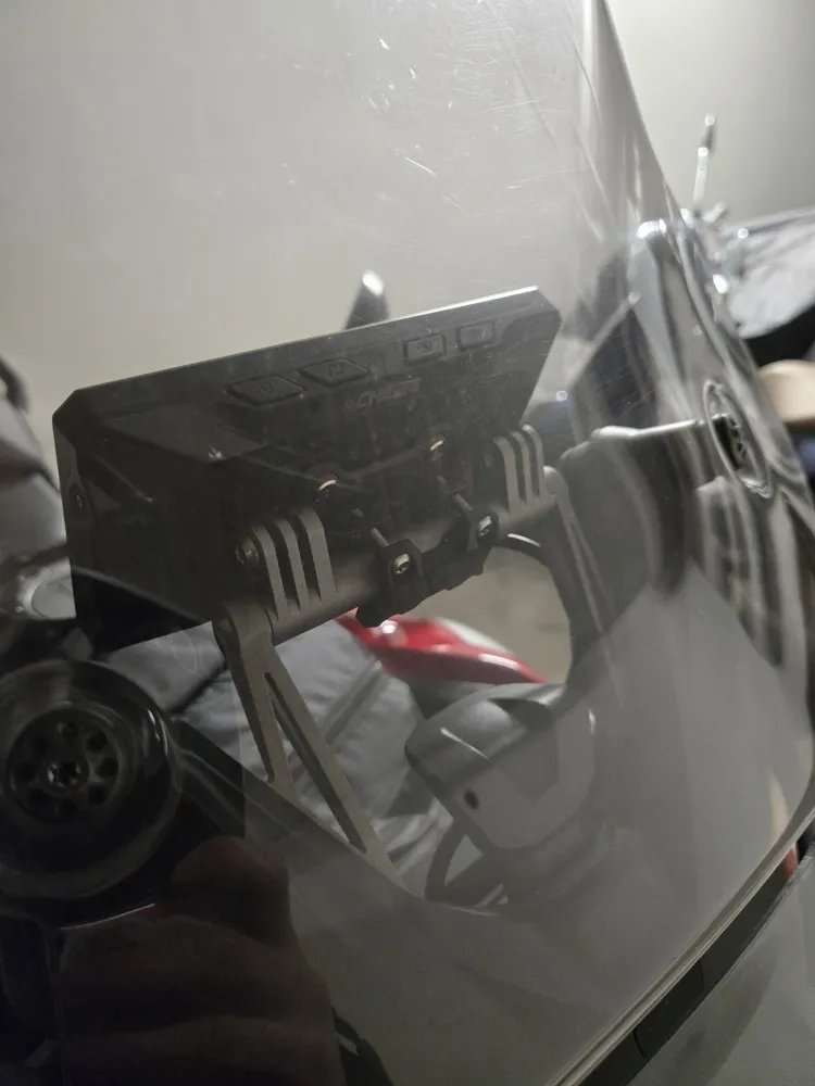
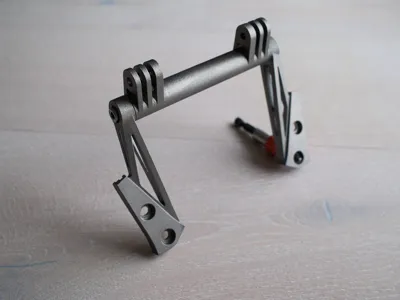
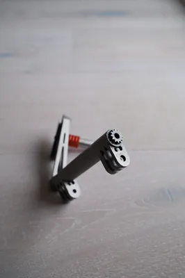
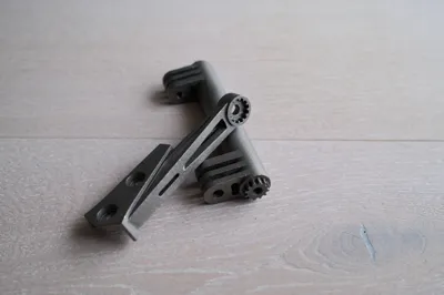
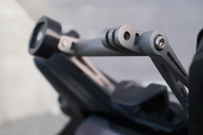
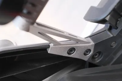
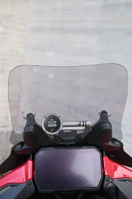
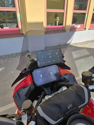
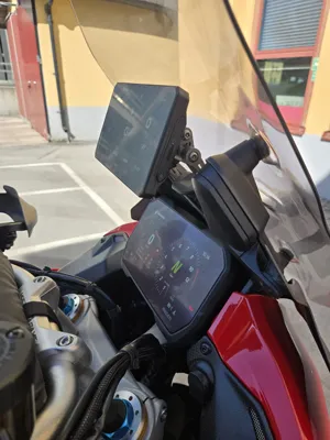
The models for the actual GPS mount are NOT intended to be printed in plastic with an FDM printer. These models are intended to be 3d printed in metal (e.g. titanium, stainless steel or aluminum) for the final product to have the proper strength and robustness. The .step files are supplied for that purpose, while the print profiles here are supplied for prototyping prints in plastic as well as producing the tapping guides. The pictures show the final product in grade 5 titanium.
Overview
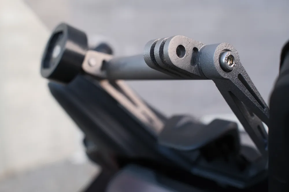
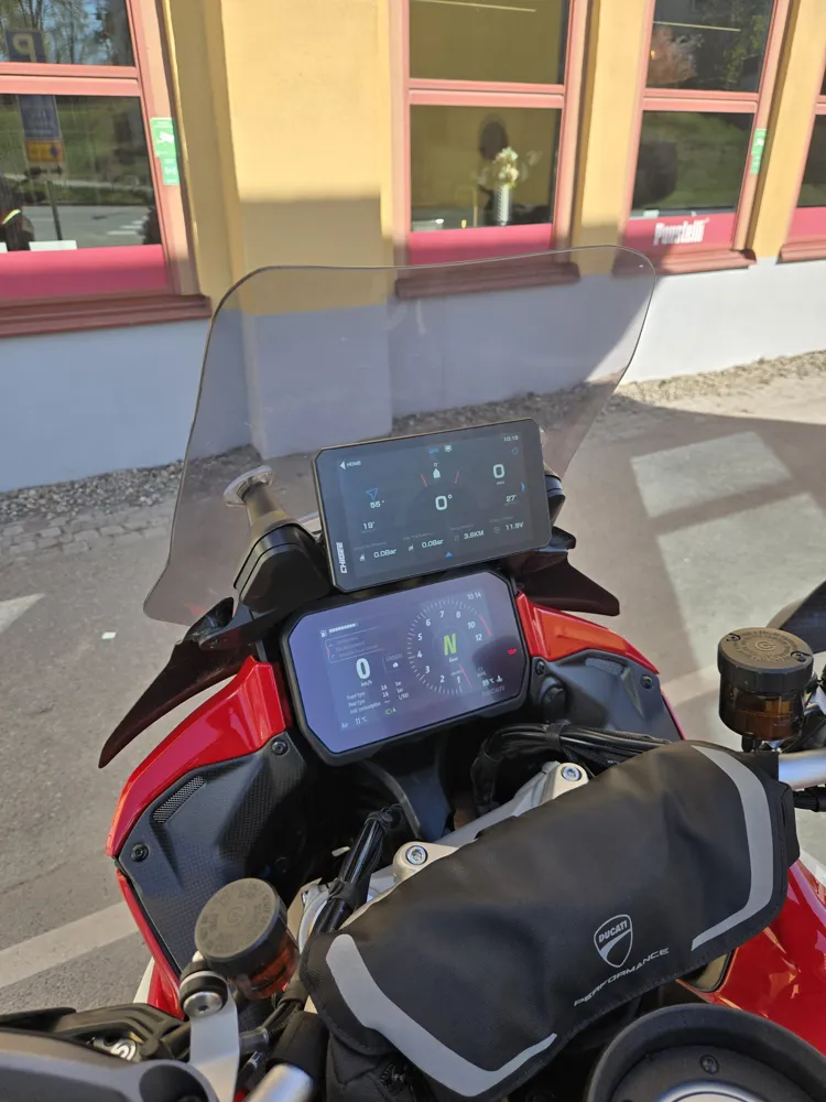
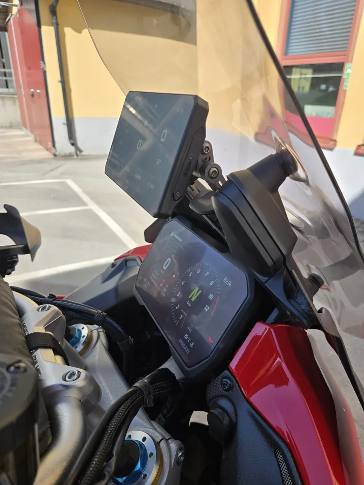
The reason for this project is that I was basically not too happy with the OEM Ducati Multistrada V4 GPS mount when it came to fitting anything else than the OEM GPS. I wanted to have the option to mount a GoPro, a Beeline or a Chigee more conveniently, maybe my phone or another action camera, or something completely different. So I designed this GPS mount system.
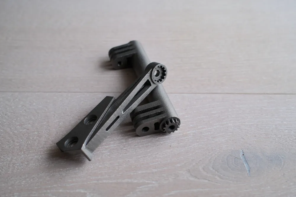
The design consist of two mount brackets that fit directly into the OEM holes, and a bridging rod between them. The rod and mount brackets are connected with a spline system allowing for adjustment of the rod position depending on preference or what is mounted.
GPS mount
There are four step files in total for the actual GPS mount:
- Two files for left and right mount parts.
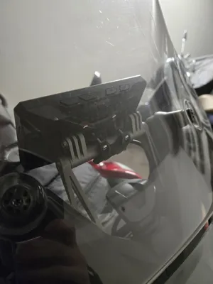
- Two different bridging rods, one with "GoPro-style" connectors and one simple rod. If you only ever is gonna use it for mounting a Chigee with the Chigee center clamp you might as well just use the simple one.
Note that some amount of post processing is required after printing these in metal:
- While not strictly needed you might want to "clear out" some support debris from inside the rod, since the rod is made hollow for weight and cost savings and the 3d-printing process will very likely leave some residual support material kicking around inside the rod. I just cleared that out with a flat head screwdriver by basically just forcefully shoving it into the rod holes and "scrambling it around".
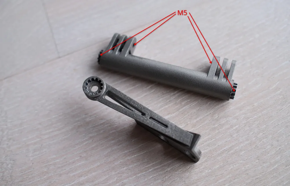
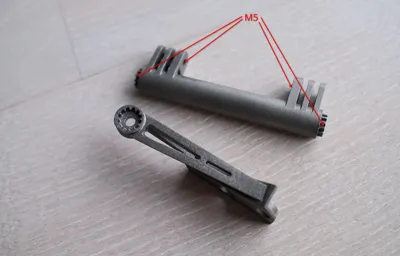
- The second thing that is required for the whole assembly to work is threading the rod ends (and the GoPro mounts if you want to use them), see image for M5 thread locations. This is intended to be normal M5 threads. Note that you should do optional step 1 before step 2 in order to not damage the threads you just made while clearing out the 3d print support debris. If you have experience with titanium from before you know this, but threading grade 5 titanium is gnarly, it is tough as balls. I would recommend a high end tap (e.g. Berner) and appropriate threading paste, I had to try a couple of different products and found this Ruko cutting paste (https://ruko.de/en/products/cutting-pastes/cutting-paste/) to work really well.
I used JLC3DP.com for printing it all using their SLM 3d printing service.
Tapping guides
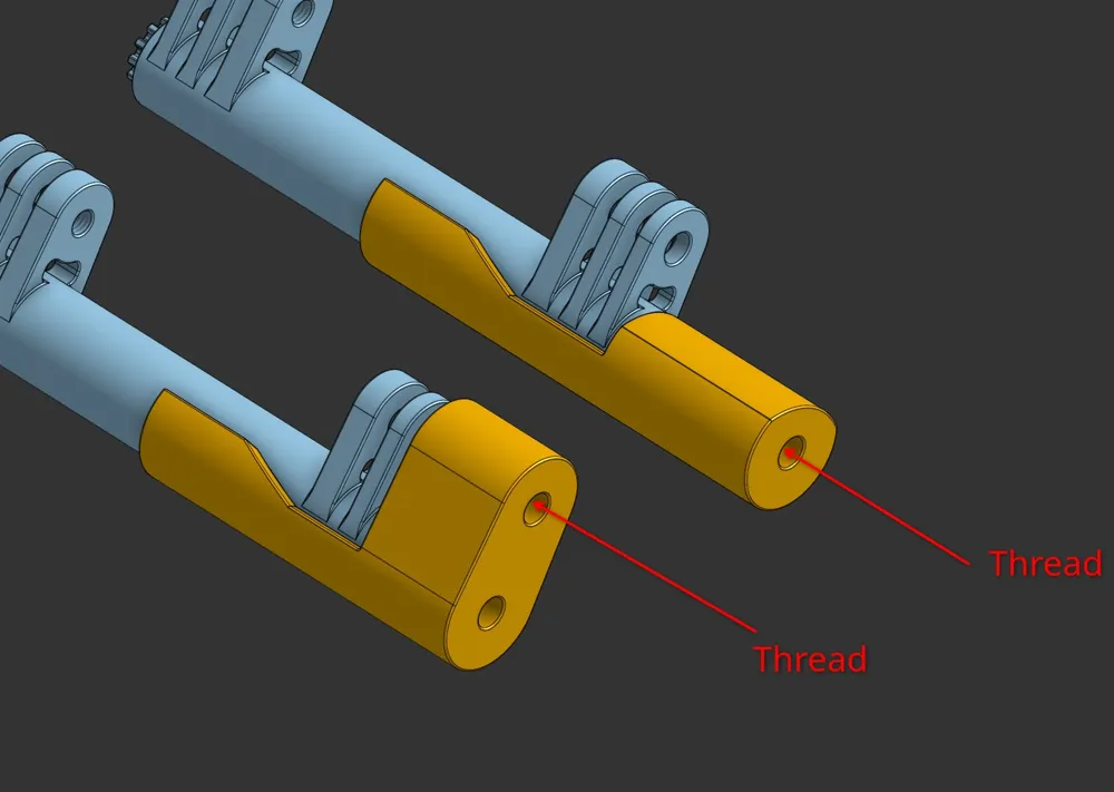
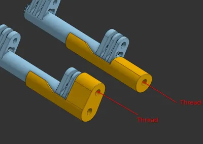
As mentioned in the the previous paragraph you need to thread the rod in order for it to be assembled. This can be done without these tapping guides but they provide a rather nice support structure for you to tap the rod perfectly straight. There are two tapping guides:
- The first tapping guide is for the rod endings itself, i.e. the threads that will allow secure the rod and the mount brackets together.
- The second tapping guide is for the threads for the GoPro mount.
License

You shall not share, sub-license, sell, rent, host, transfer, or distribute in any way the digital or 3D printed versions of this object, nor any other derivative work of this object in its digital or physical format (including - but not limited to - remixes of this object, and hosting on other digital platforms). The objects may not be used without permission in any way whatsoever in which you charge money, or collect fees.


Comment & Rating (0)