
KeyRing CW key holder
Print Profile(1)
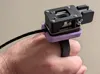
Bill of Materials
- 10mm x 3mm magnet x 8: Circular magnets, 10mm dia x 3mm neodymium
Description
KeyRing CW Key Holder — Build Guide
Model: KeyRing CW Key Holder by HamKids73 Tags: ham · morse code · SOTA · POTA License: CC BY-NC-SA 4.0
What Is This?
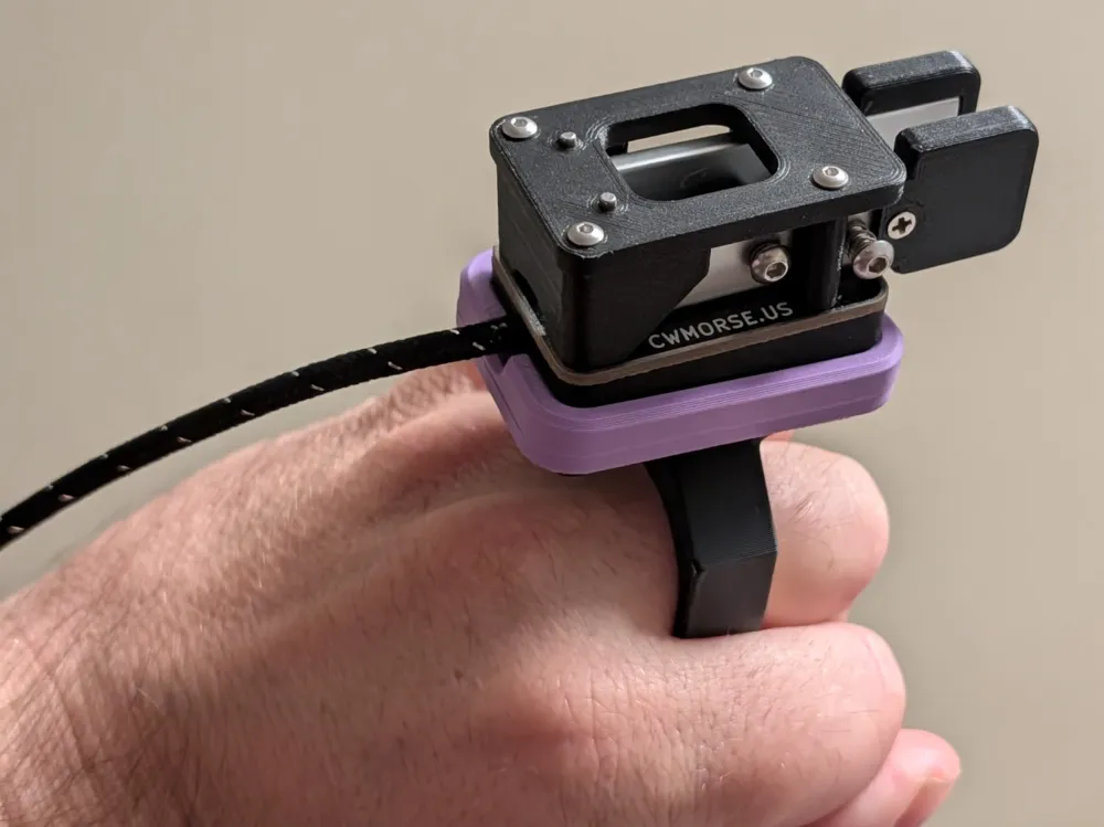
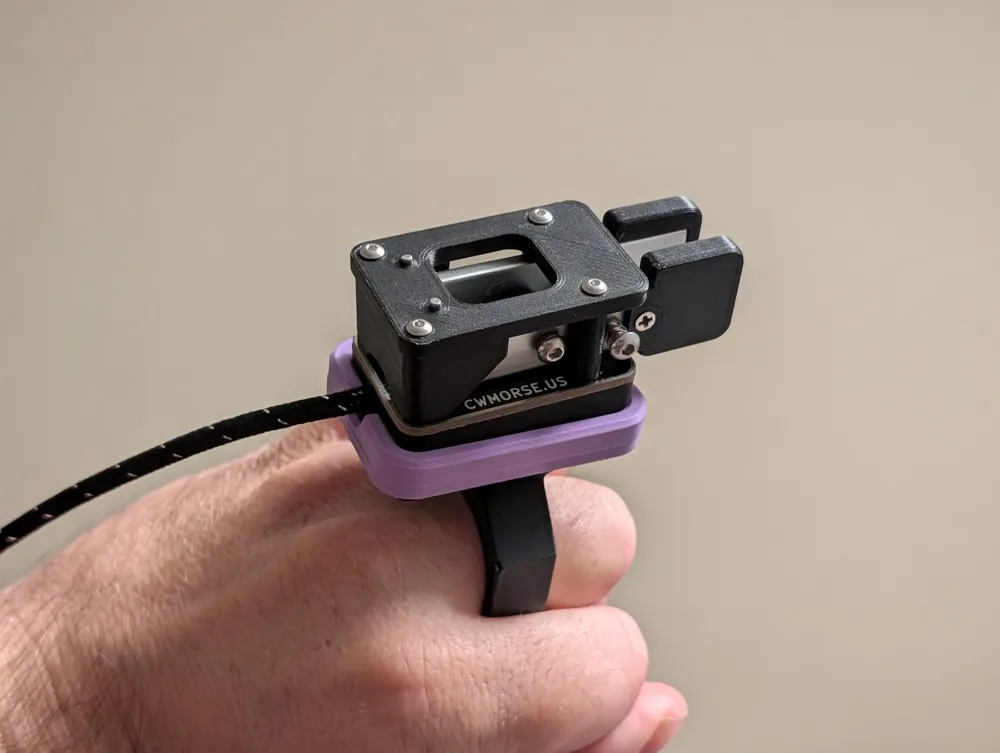
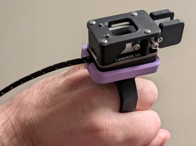
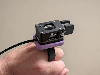
This is a parametric finger-mount ring for a portable CW (Morse code) key. It slides onto two fingers and holds your key right at your fingertip — keeping both hands free and the key instantly accessible. Perfect for SOTA, POTA, and any portable operation where you need a comfortable, hands-free keying position.
The system has two printed parts:
- The Ring — slides onto your fingers; accepts press-in magnets on the back
- The Interposer (optional) — a platform adapter for keys that don't have built-in magnets; has print-in-place magnet pockets
Bill of Materials
| Item | Qty | Notes |
|---|---|---|
| 10mm × 3mm neodymium disc magnets | 8 | Circular, N35 or stronger recommended |
| Your CW key | 1 | Measured before printing |
Step 1 — Measure Your Hand
Before generating or printing anything, you need two measurements from your hand using calipers. A digital caliper (like a Mitutoyo) gives the best accuracy.
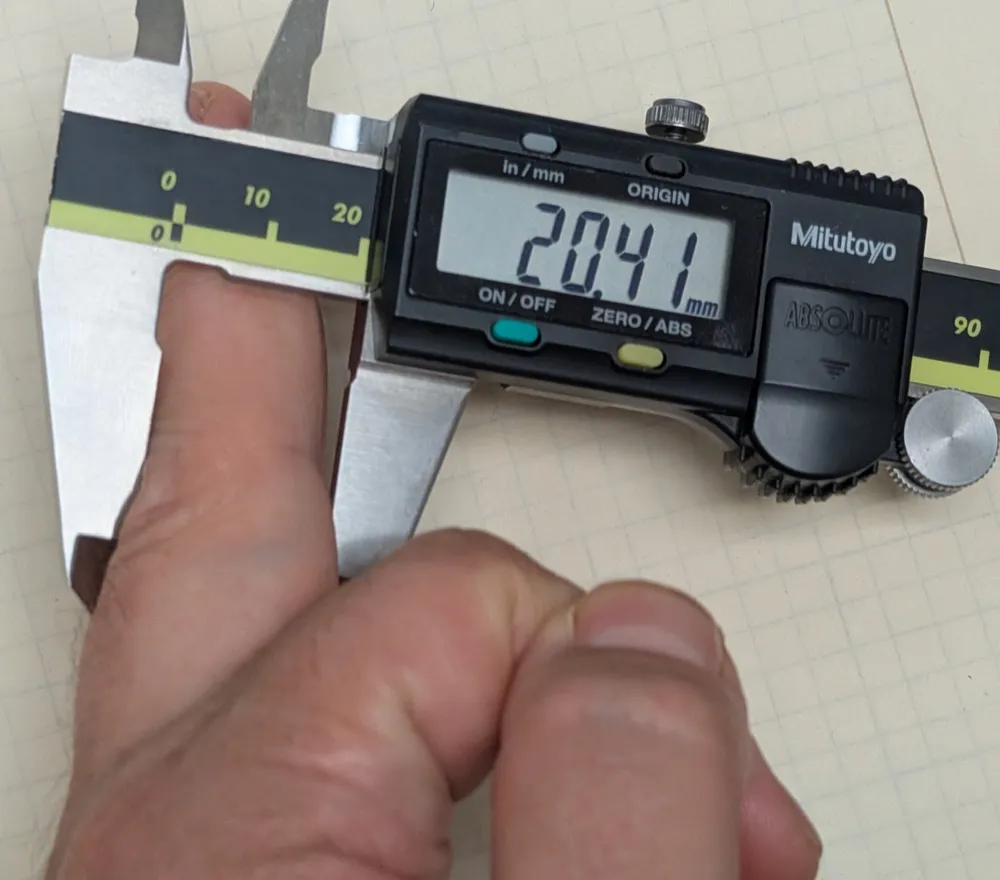
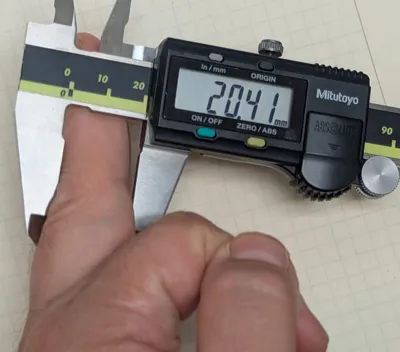
Measurement A: Knuckle Height (FingerSize)
Measure the height of your largest knuckle — the knuckle the ring will need to pass over to seat on your finger. This is the critical clearance dimension.
Example: The photo shows a reading of 20.41 mm. This goes into the FingerSize parameter.
Tip: Measure snugly but not tight. The ring seats below the knuckle and should slide over it without forcing.
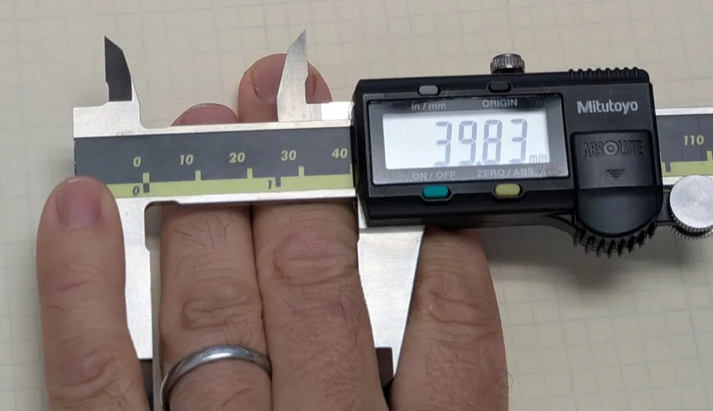
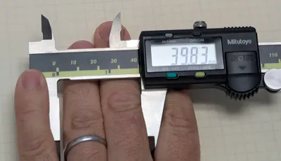
Measurement B: Two-Finger Width (FingerWidth)
Measure the combined width of the two fingers the ring will sit on, side by side, at the point where the ring will rest.
Example: The photo shows a reading of 39.83 mm. This goes into the FingerWidth parameter.
Tip: You want the ring to just graze the knuckle — not tight. Add ~0.5–1 mm of clearance to your measured width if you want a relaxed fit.
Measurement C & D: Your CW Key
Measure your key's width and length where it will sit on the platform:
- KeyWidth — width of the key body
- KeyLength — length of the key body
These dimensions define the pocket or platform that holds the key, whether you're using the interposer or printing the platform directly.
Step 2 — Generate the Model
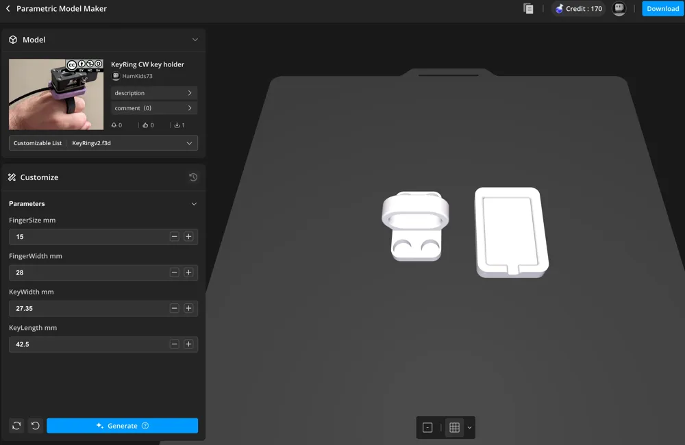
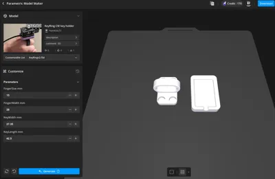
Open the model in MakerWorld's Parametric Model Maker and enter your measurements:
| Parameter | What It Controls | Your Value |
|---|---|---|
| FingerSize mm | Knuckle clearance height | (from Measurement A) |
| FingerWidth mm | Width across two fingers | (from Measurement B) |
| KeyWidth mm | Width of your CW key | (from Measurement C) |
| KeyLength mm | Length of your CW key | (from Measurement D) |
After entering all values, click Generate and wait for the model to update in the 3D preview. Once satisfied, click Download to get the .3mf file.
Alternative: If you don't need custom sizing, you can skip the parametric generator entirely and download the .3mf directly from the print profile on the model page. This gives you a pre-configured, print-ready file with refined settings already dialed in — useful if the default dimensions happen to fit your hand and key.
Step 3 — Slicer Setup
Open the downloaded .3mf in Bambu Studio (or your preferred slicer).
Recommended Print Settings
Use default quality settings with these specific changes:
| Setting | Value | Notes |
|---|---|---|
| Walls | 3 | Up from default 2 — improves ring strength |
| Infill pattern | Gyroid | Better isotropic strength than grid |
| Infill density | 15% | Default is fine |
| Supports | On — build plate only | See support rules below |
⚠️ Support Rules — Read Carefully
Supports must be applied selectively. Getting this wrong will ruin the interposer:
- Key ring: Enable supports. The arch geometry needs support from the build plate or it will sag.
- Interposer: No supports at all. The magnet pockets are open-topped holes — if supports are enabled globally they will fill the pockets and you won't be able to insert the magnets.
- Magnet holes: Never add supports inside or above these holes for the same reason.
In Bambu Studio, set support type to "On build plate only" — this prevents supports from growing up inside any cavities or holes on the model while still supporting the ring arch from below.
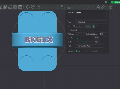
Adding BKG / Callsign Text
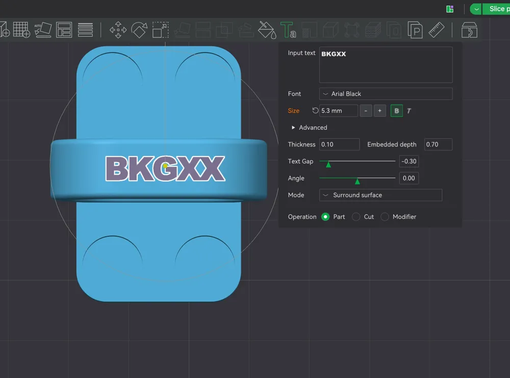
The ring band is wide enough to carry your BKG number or callsign, added directly in Bambu Studio using the Text tool:
- Select the ring object in the 3D view
- Click the Text tool in the toolbar (the Ta icon)
- Click on the band surface of the ring — Bambu Studio will wrap the text around the surround surface automatically
- In the text panel, set:
- Input text: your BKG number (e.g. BKGXX) or callsign
- Font: Arial Black (bold, reads well at small sizes)
- Size: ~5.3 mm (adjust to taste)
- Thickness: 0.10 mm
- Embedded depth: 0.70 mm
- Text Gap: –0.30 (tightens letter spacing slightly)
- Mode: Surround surface
- Operation: Part (raises text proud of surface — use Cut instead if you want recessed/engraved text)
- Position with the Angle slider if needed to center it on the band
The text wraps around the ring band automatically in Surround surface mode. "Part" mode prints the text as raised letters; "Cut" mode embosses it into the surface. For a two-color print, use Part mode and assign the text a different filament color.
Adding a Pause for Print-in-Place Magnets (Interposer Only)
The interposer has pockets for print-in-place magnets. You must add a pause at the correct layer so you can drop the magnets in before the printer covers them.
- In Bambu Studio, right-click on the layer bar at the top of the magnet holes in the layer preview
- Select Add Pause at that layer
- When the printer pauses, drop a 10mm × 3mm magnet into each pocket — see the magnet alignment section below before printing so you know the correct orientation
- Resume the print — the next layers will encapsulate the magnets
Step 4 — Magnet Alignment
Getting polarity right before anything is pressed in or encapsulated is the most important step. Misaligned magnets mean the ring and key will repel instead of attract. Follow the method below for your setup.
The Stack-and-Transfer Method (Recommended)
Neodymium disc magnets naturally stack with alternating poles — if you pick up a stack from a pile, every magnet in the stack is already co-aligned (N–S–N–S). This is your advantage. The goal is to transfer that aligned stack directly into the parts without losing orientation.
If You Are Using the Interposer
The interposer magnets are print-in-place (encapsulated during printing), and the ring magnets are pressed in afterward. Do this in two stages:
Stage 1 — Load the interposer during printing:
- Pick up all 8 magnets as a single stack — they self-align when stacked
- Mark the top face of the stack with a marker dot so you can tell which end is which
- Separate 4 magnets for the interposer, keeping them stacked and oriented correctly
- When the printer pauses, drop one magnet into each pocket with the marked face consistently up (or consistently down — just be consistent across all 4 pockets)
- Resume printing to encapsulate them
Stage 2 — Load the ring after printing:
- Take your remaining 4 magnets (still stacked and co-aligned from step 1)
- Hold the interposer with its magnet face up
- Lower the magnet stack toward the interposer — it will snap onto the interposer face in the correct mating orientation (the ring-side face is now on top)
- Separate one magnet at a time from the top of the stack and press it into the ring pocket in that same orientation
- Repeat for all 4 ring magnets
Because you transferred from the interposer's face, the ring magnets are automatically set to attract — no guesswork needed.
If You Are Using a Key Without an Interposer
Your key either has built-in magnets or a metal base that the ring magnets will attract to directly. The process is similar:
- Stack all 4 ring magnets together
- Hold the magnet stack against the back of your key in the position it will sit — it will snap to the correct attracting orientation
- Note which face of the stack is facing away from the key (this is the face that goes into the ring pocket)
- Press each magnet into the ring pocket one at a time from the stack, keeping that same face orientation
The key acts as your reference — mate to it first, then transfer to the ring.
General tips:
- Work on a non-magnetic surface (wood or plastic) so stray magnets don't jump around
- Keep the stack together as long as possible — separating them individually loses your orientation reference
- A marker dot on one face of your stack at the very start saves a lot of confusion
Step 5 — Press-In Magnets for the Ring
After completing the alignment steps above, seat the ring magnets:
- Let the ring fully cool before pressing magnets in
- Press each 10mm × 3mm magnet into its recess on the back of the ring, using the orientation established in Step 4
- Use the flat end of a pencil or a small dowel to press them flush — avoid pushing with your finger as magnets can pinch
- Do a quick test: hold the ring near the interposer or key — they should snap together cleanly with no repulsion
If the fit is too loose, a small drop of CA (super) glue holds them securely. If too tight, gently ream the pocket with a 10mm drill bit by hand.
Step 6 — Assembly & Use
- Slide the ring onto your two preferred keying fingers — it should slip over the knuckle and seat comfortably below it
- Attach your key to the ring via the magnets — it will snap on with a satisfying click
- For keys without built-in magnets, place the key on the interposer first, then attach the interposer to the ring
The magnetic connection is strong enough to hold the key during normal keying but releases cleanly when you pull it off.
Printing Tips & Troubleshooting
| Issue | Solution |
|---|---|
| Ring too tight over knuckle | Add 1–2 mm to FingerSize and regenerate |
| Ring feels loose/sloppy | Reduce FingerWidth by 0.5 mm |
| Key doesn't sit flat | Check KeyLength / KeyWidth match your actual key |
| Magnets falling out of ring | Add a drop of CA glue |
| Print-in-place magnet pockets filled with support | Set supports to build plate only; never enable supports on the interposer |
| Print-in-place magnets shifted during print | Ensure magnet is seated fully flush before resuming; slow the next layer in slicer if needed |
| Arch droop on ring | Confirm supports are enabled for the ring (build plate only) |
| Ring feels weak or flexes | Confirm walls are set to 3 and gyroid infill is selected |
73 de HamKids73 — Good luck and enjoy the portable ops!
Documentation (1)
License



Comment & Rating (0)