Soldering Assistant V2: Modular Sliding-Pin Jig


Print Profile(1)

Description
Soldering Assistant Pro V2: Modular Sliding-Pin Jig

If you have ever struggled to keep female headers straight, fought with components that won't stay flat on a PCB, or dealt with the hassle of switching jigs for different microcontroller widths, this tool is for you. While standard breadboards work for male headers, they are often a hassle for everything else. This soldering platform is an upgraded, dedicated "third hand" for your workbench, designed to ensure perfect alignment for any board size.
The Problem it Solves
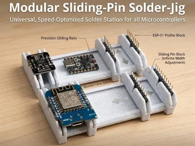
Most soldering jigs are either too generic or too clunky. Fixed-width jigs require a new block for every specific board you use. This upgraded modular system eliminates that problem, utilizing a sliding rail system to give you infinite width adjustment. Now you can solder perfectly straight headers on everything from a narrow Arduino Pro Mini to a wide ESP32 development board without skipping a beat.
Key Engineering Features
- Precision Sliding Pin Holders: Gliding on high-tolerance rails, the movable pin blocks can be instantly adjusted to match the exact width of your target microcontroller.
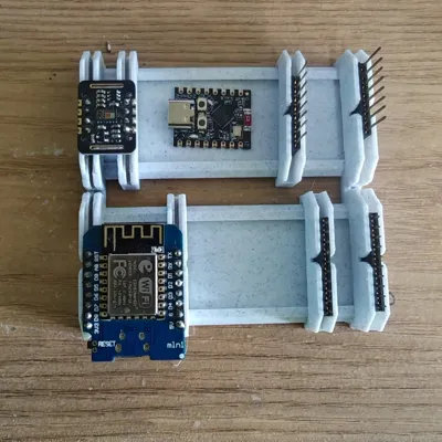
- Standard 2.54mm Pitch Design: Engineered specifically to securely hold standard 2.54mm pin headers perfectly perpendicular to your PCB. The blocks are configured with one side optimized for female headers, and the opposite pair designed to securely grip male headers.
- Modular Frame System: The base rails and sliding blocks are completely modular. Connect multiple rail frames together to create a custom-sized, multi-board workstation.
- Friction Fit & Stability: Subtle internal tolerances keep the sliding blocks firm once positioned, ensuring nothing shifts while applying solder.
Recommended Print Settings
- Material: PETG or ASA is highly recommended for its heat resistance near your soldering iron tip. PLA works perfectly fine as long as you are careful!
- Layer Height: 0.16mm for the sliding parts and rails (to ensure a smooth glide and tight tolerances), and 0.2mm for the fixed blocks.
- Walls: 3 walls for structural rigidity.
- Infill: 15% (Gyroid).
- Support: Not required. Print in the default orientation.
How to Use
- Assemble your modular base rails by connecting the frames.
- Slide the adjustable pin blocks horizontally to match the exact width of your target PCB.
- Insert your standard 2.54mm male or female pin headers into their respective designated slots on the blocks.
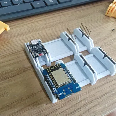
- Drop your PCB onto the pins so it rests perfectly flat.
- Solder with confidence!
I’d love to see your builds! If this modular system speeds up your prototyping workflow, please leave a rating and share a photo of your setup.
Comment & Rating (30)