
Split-Ring Dual Joined-Cycloids 105:1 gear train
Print Profile(1)
Description
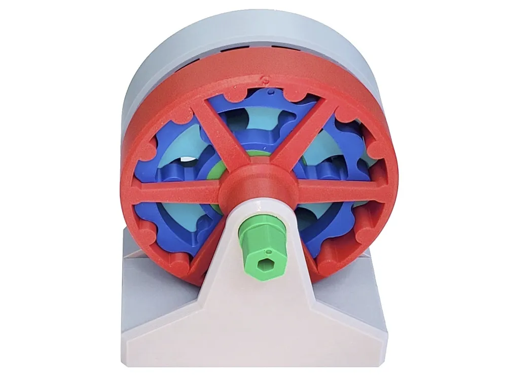
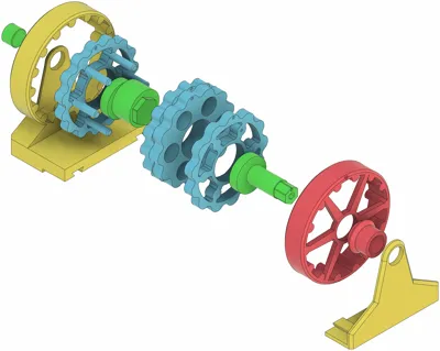
Like Wolfrom gear trains, Split-Ring Joined-Cycloid drives provide high reduction ratios in a small volume, but with less parts and a much simpler design.
This gear train is based on a Dual Joined-Cycloid gear which, unlike the simpler Single Joined-Cycloids gear, presents balanced centrifugal forces, and symmetrical forces on the stator and output rings, making it potentially more suited for high load torque and higher speed.
So I designed this simple model to get familiar with its principle. It has a 105:1 reduction ratio, 3mm eccentricity and is 120mm wide.
The Fusion360 CAD model (very messy), STEP, STL and 3MF files are attached.
More details on this drive type (CAD, diagram, principle, test results, resources) in this post: https://raphtronic.blogspot.com/2026/05/diy-split-ring-dual-joined-cycloids.html
______________________________________________
Printing
Settings
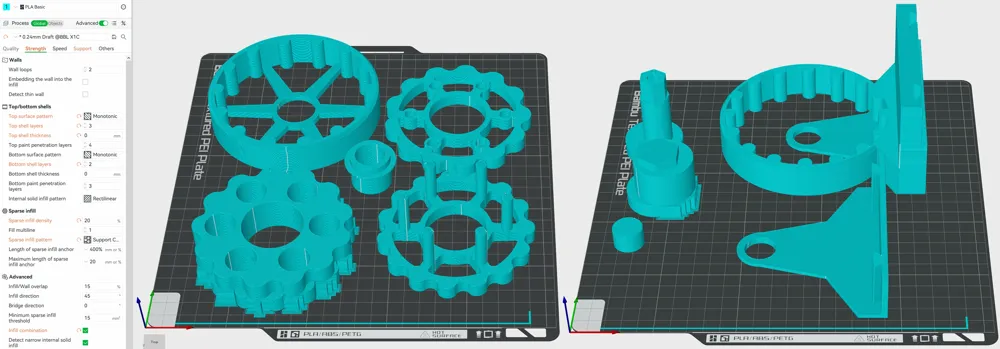
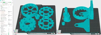
- 0.4mm nozzle, 0.24 layer height
- 2 walls, 3 top, 2 bottom
- 20% Support Cubic infill
- Normal Auto support, 10° Threshold Angle
- 0.5mm Support/object XY distance (easier to break supports free)
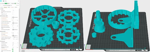
Note that due to the usual Fusion360 Export bug when handling cycloidal surfaces, the discs had to be saved as STL files instead of the more desirable STEP format.
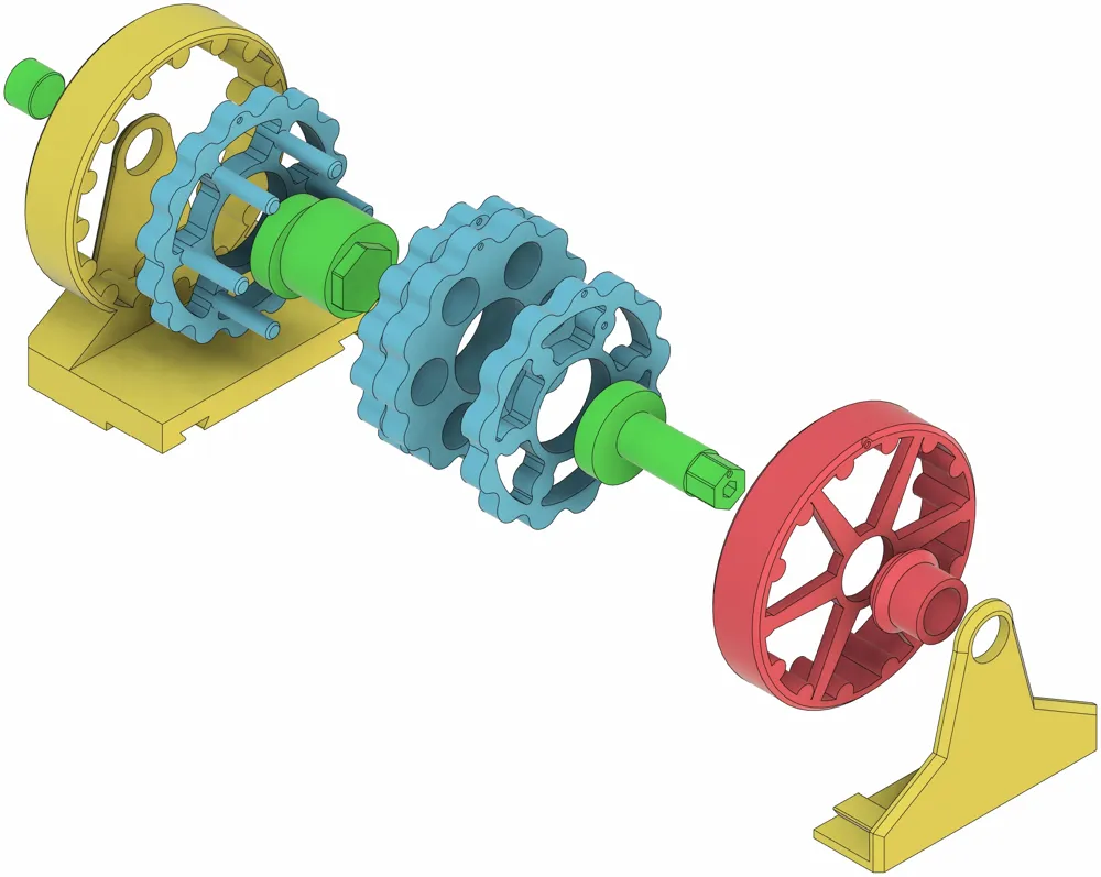
Assembly
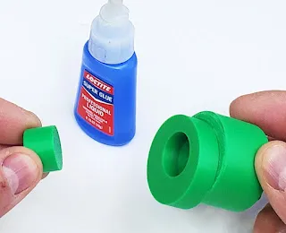
Glue the shaft end on:
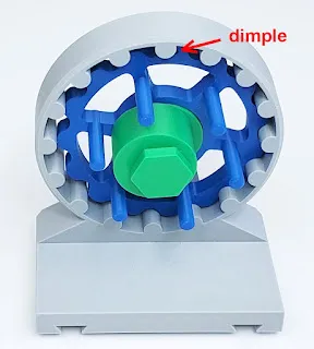
Install the cycloidal pin-disc, dimple up, and the partial shaft:
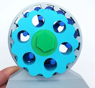
Install the joined-cycloids, dimples up:
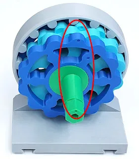
Glue the front pin-disc onto the pins, and glue on the front part of the shaft, ensuring that the dimples are all aligned:
Glue the output hub to the wheel:
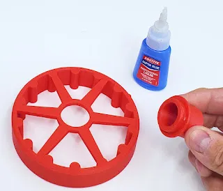
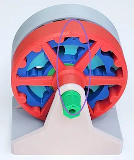
Install the output wheel and the front of the casing:
License



Comment & Rating (0)