Relay Housing for Toggling Misc Devices


Print Profile(1)

Bill of Materials

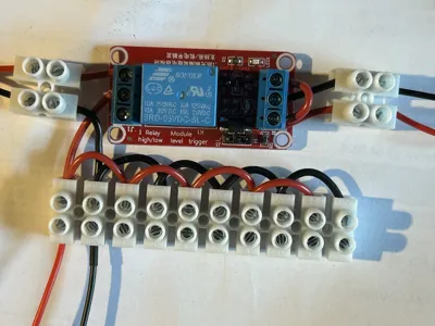
- 5V Relay x 1: 10 poles on a long strip and 2x2 poles on short strips
- 2,5 mm² Luster Terminal x 14: 10 poles on a long strip and 2x2 poles on short strips
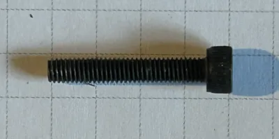
- M3 x 20mm Socket Head Screw x 4: Flat head might also work
- Some AWG20-22 Wires x 2: Preferably non-combined (single-pole) stranded wire with non-tinned ends. For best readability I'd use red & black for + & - Poles; ~20-40cm each
- Some kind of triggered 5V signal power x 1: e.g. USB-Power toggled by a motion sensor
Description
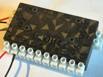
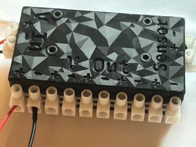
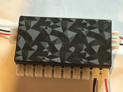
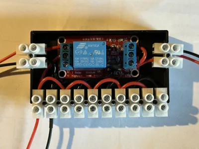
This is a clam shell enclosure to attach devices to a relay to be toggled. Practically I use this to toggle my Bento Box and enclosure lights by a motion sensor on the Y-axis housing of my A1 mini.
The motion detector toggles a 5V low power input signal, which in turn toggles this relay to switch any power source (in my case a more Ampere carrying 5V USB power plug, but the relay supports up to AC 250V/10A or DC 30V/10A). There is one Power input on the left, 5 parallel wired outputs and a “sensor” input for the 5V toggle power. Practically a single output would probably be enough, but this appeared more convenient to me, if I decide to add more consumers later on.
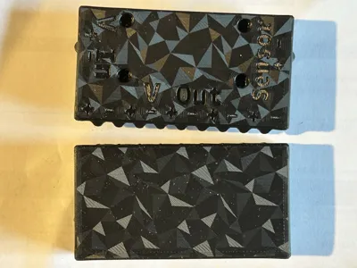
The lid is labelled for easier wiring and the images show how the wiring is to be performed. To hold everything together you'll need 4 M3x20mm inner hex socket head screws (mine are ~22mm incl. head or ~18 without it - labelled 20mm)
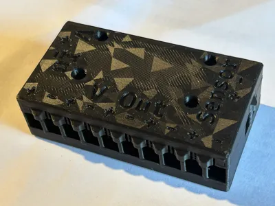
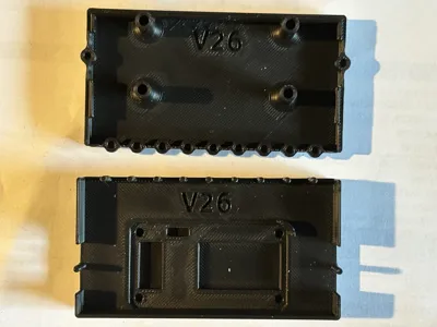
Never mind the surface finish, that's an effect plate and never mind the V26 on the inside - that's from my prototype versioning; you won't have that on your box.
The model should print just fine without supports. You might have to poke through some stray lines of filament in the opening of the screw holes though. Just push the screw in with a little force. It should drop down though the boss so it can directly be screwed through the PCB into the base. There is also a little wall around the lower left PCB corner, because for me the wires kept coming into the boss's way. This ledge will help you keep the wires out of the weeds.
I used this material:
Luster Terminals - https://www.amazon.de/dp/B0002YYZPU (in total 14 terminals/poles are needed - 2x2 + 1x10 - The image in the listing is NOT what you'll get. They are not rounded on the bottom, they are cornered like you can see in my photos)
Relay - https://www.amazon.de/dp/B0CSJQZ89V
Screws come from this box - https://www.amazon.de/dp/B0CKF1RP4D
Wires - https://www.conrad.de/de/p/tru-components-1571019-litze-lify-1-x-0-50-mm-rot-10-m-1571019.html and the black version of it. Probably overkill for my 5V 1-4A. This equates roughly AWG20. AWG21-22 would probably be just fine.
Boost Me (for free)
Do you want more flexible and elaborate as well as functional print models? Give me a boost and I continue uploading all my relevant creations!
License
You may create derivative works based on this object, provided that all such derivative works are published exclusively on the MakerWorld platform and include proper attribution to the original creator. You may not share, upload, host, distribute, or publish this object—or any derivative work of this object—on any other digital platform, marketplace, or distribution channel. Commercial use of this object and any derivative works is strictly prohibited. This includes, but is not limited to, selling, renting, sublicensing, or using the object in any context in which you receive monetary compensation or other financial benefits.
Comment & Rating (0)