
China Leather Shoe Patcher Motorisation

Print Profile(1)
Description
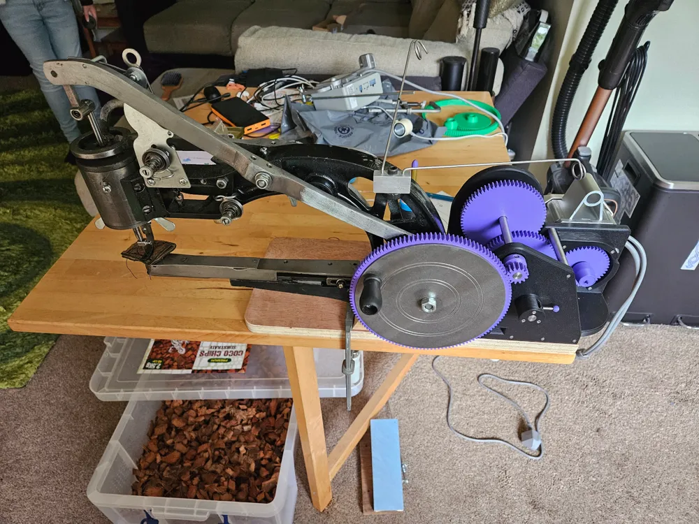
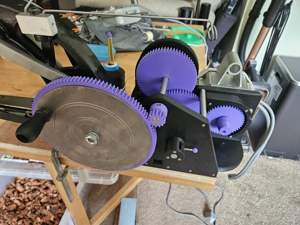
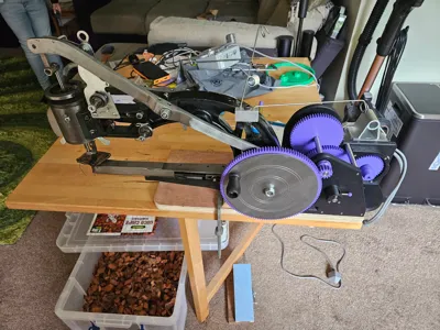
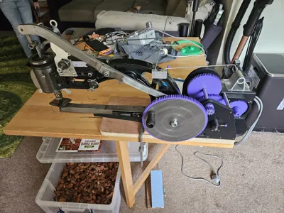
I have a cheap chinese leather shoe patcher sewing machine that I wanted to motorise.
I posted the results on a Facebook group and have been overwhelmed with the response. I'm posting the files here because of this.
I have added a print profile for my design BUT there are other bits that are not 3d printed that need to be made and other standard bits of hardware required. I have an H2D printer so the parts are layed out for this. You may have to shuffle parts about onto different plates dependant on your printer. Supports are needed. I oriented the front, middle, and rear frames in the print profile so that no supports are placed in the bearing or motor boss recesses. The double gear does however have supports in one of the bearing recesses.
This is not just a simple print and it's ready to go thing. I used my mill and lathe plus various taps and dies etc to make this. The way that I mounted the motor uses M4 threaded holes in the motor face plate that are not a regular pattern (intended to be used to mount the belt guard) and appear to have been drilled by hand. The hole positions in the model probably won't match another motor of the same type. Modifications probably will be required.
I'm UK based so have used metric hardware. I'm aware that those across the pond may not have easy access to this and this machine is popular over there. Due to this I've uploaded the Fusion .f3d file so that modifications are easier.
I based my design on this motor - https://www.amazon.co.uk/dp/B0CQLTRSJP It has a 15mm shaft with a 5mm keyway and an M12 thread.
My sewing machine is bolted/screwed to a baseboard and is sat on a riser block that is 38.75mm high (a piece of 3x2 if I remember correctly). This dimension is not critical but if is smaller then the frame assembly might contact the sewing machine frame before meshing with 14 tooth gear with the handwheel gear correctly. All of the threaded holes on the model were cleaned up after printing with an approprite tap.
I used :-
4x 6200-2RS bearings (30mm OD 10mm ID 9mm Wide)
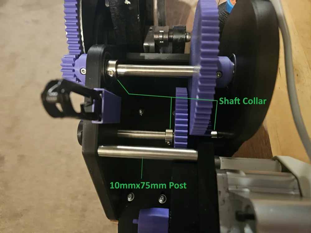
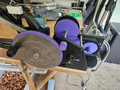
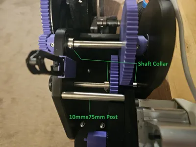
3x 10mm shaft collars (the ones I used are 8mm wide) - look at the photos for the collar locations. I filed a flat spot onto the shafts for the set/grub screws so as to not cause burrs on the shaft OD.
One 10mm diameter shaft, 75mm long and threaded each end on the lathe M3 11 or 12mm deep, this is used as a post to separate and brace the front and middle frames.
One 10mm shaft 144.93 long with 2x 3mm cross drilled holes. Positioned 19.13 and 124.93mm from the "front" end. The "front" end being the end with the 14 tooth gear that drives the big gear on the sewing machine handwheel.
One 10mm shaft 162mm long with a cross drilled hole threaded M3 18mm from the “front” end. Used to attach the Handle for the engage/dis-engage mechanism.
One 3mm shaft approximatly 35mm long. Threaded M3 for 9mm on one end (to go into the 10mm shaft) and 5mm on the other end for the ball end.
3 x M4x20 Pan head machine screws plus washers to mount the motor.
Lots of M3x20 cap head machine screws (used to hold the various bits of frame together and to cross pin the 14 tooth and 67 tooth gears to the 10mm shaft)
3x M3x30 cap head machine screws (used to hold the engage/dis-engage mechanism onto the front frame)
3x M3x25 cap head machine screws (used to hold the motor gear guard to the midlle frame)
2x M3x18 cap head machine screws (used to mount the 10mmx75mm long post between front and middle frames)
1x M3x33 (I shortened a 35mm) cap head machine screw (used to fix the rear frame through the printed post to the middle frame)
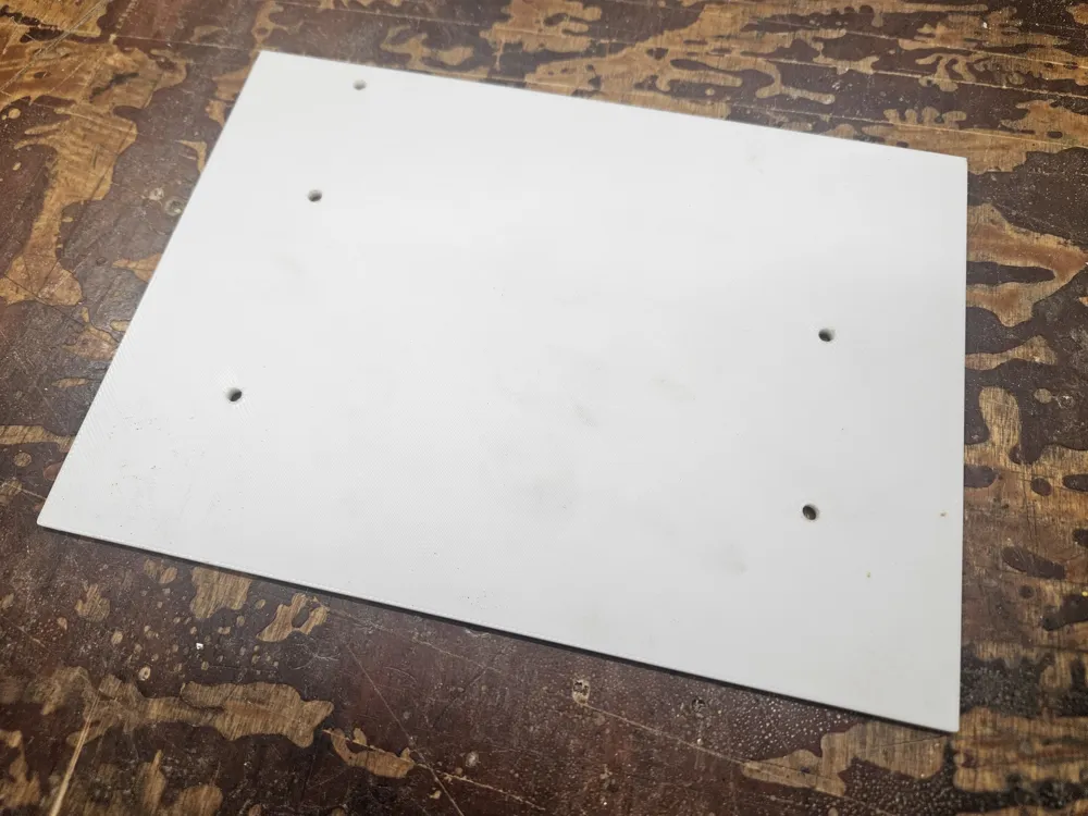
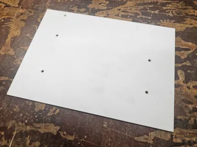
5x No8x1" Pan head self tapping screws to hold the whole frame assembly down onto a base board. (there is a 3d printed template (white in the photos) for the screw locations. The front edge of this template should be in line with the rear of the handwheel.)
One 10mmx3mm Magnet for the bobbin holder. (The print needs paused to insert the magnet part way though. This is done in the uploaded print profile along with painted supports to ensure no supports are printed in the magnet cavity)
I hope I haven't missed anything. If I have (probably) or you have questions please comment or message me and I'll do my best to answer.
License



Comment & Rating (2)