Bevel Gear Educational Model


Print Profile(1)
Bill of Materials


- Magnet x 6: 5x3 (round)
- Tapered roller bearing x 2: 32006-X | 30 x 55 x 17 mm
- Tapered roller bearing x 2: 32004-X | 20 x 42 x 15 mm
- Heat-Set threaded inserts x 21: M3x4x5 (Voron Size)
Description
Boost Me (for free)
You like this model? Support me with a boost!
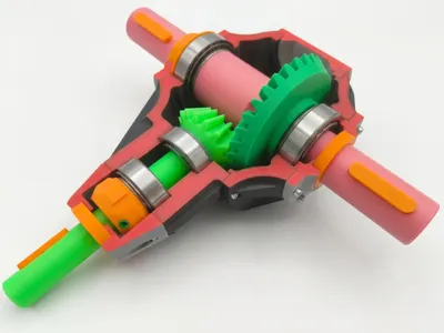
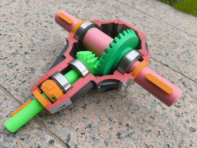
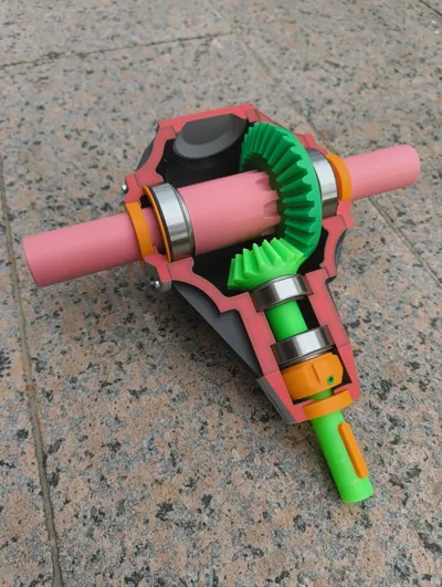
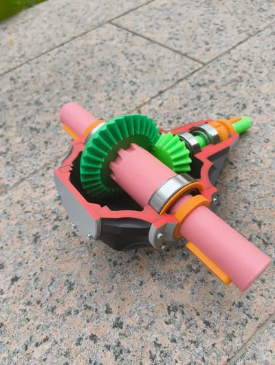
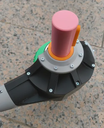
This is a bevel gear drive intended for demonstration and teaching purposes. As I am not personally involved in gear design and lack professional expertise in this area, the construction of this gearbox is not fully compliant with standards or industry practices in all aspects.
This model requires a lot of supports! The mechanical engineering aesthetic of the parts and a support-free construction are mutually exclusive. Given that the tolerances are very tight, I recommend printing only with supports using Bambu PLA Support Material or PETG.
When printing with PLA supports, quite a bit of sanding may be necessary.
What this model illustrates:
- Adjusted mounting of Tapered Roller Bearings (in X and O arrangement)
- Adjustment of bearing clearance using shims and a shaft nut
Assembly sequence and process utilizing housing covers
What this model does not depict:
- Realistic, industry-standard design parameters (shaft diameters, module, screw sizes)
- Fit precision of components (clearance, transition, and interference fits)
Realistic cast housing geometries
Assembly
Preparation of the Model:

- Embedding all Heat-Set threaded inserts into both covers and the housing.
- Gluing the magnets into the three machine keys and the shafts (Caution: ensure correct polarity!).
Assembly Sequence:

Mount the inner ring of the tapered roller bearing onto the pinion shaft.

Insert the corresponding bearing outer ring into the housing bore.

- Insert the pinion shaft through the housing opening.
- Slide the inner ring of the second tapered roller bearing onto the pinion shaft.
Screw the shaft nut down to secure and adjust the bearing clearance.

Pre-assemble the 30mm shaft: Slide on the bevel gear and both bearing inner rings.

- Loosely position the pre-assembled shaft into the housing.
Fasten the large housing cover.

- Insert the bearing outer ring on the gear side.
Mount the bearing cover on the gear side (without a shim). CAUTION: This cover has a longer projection of 3 mm.

- Insert the second bearing outer ring on the opposite side.
- Insert the shim. Bearing arrangement is typically adjusted via shims of varying thickness (only realized with one shim in this model).
Fasten the corresponding bearing cover.

Mount the front pinion shaft cover and the end cap for the pinion shaft on the opposite side.

- Insert all shaft seals (optionally, these can also be glued in before mounting the covers).
- Insert the machine keys.
Comment & Rating (4)