
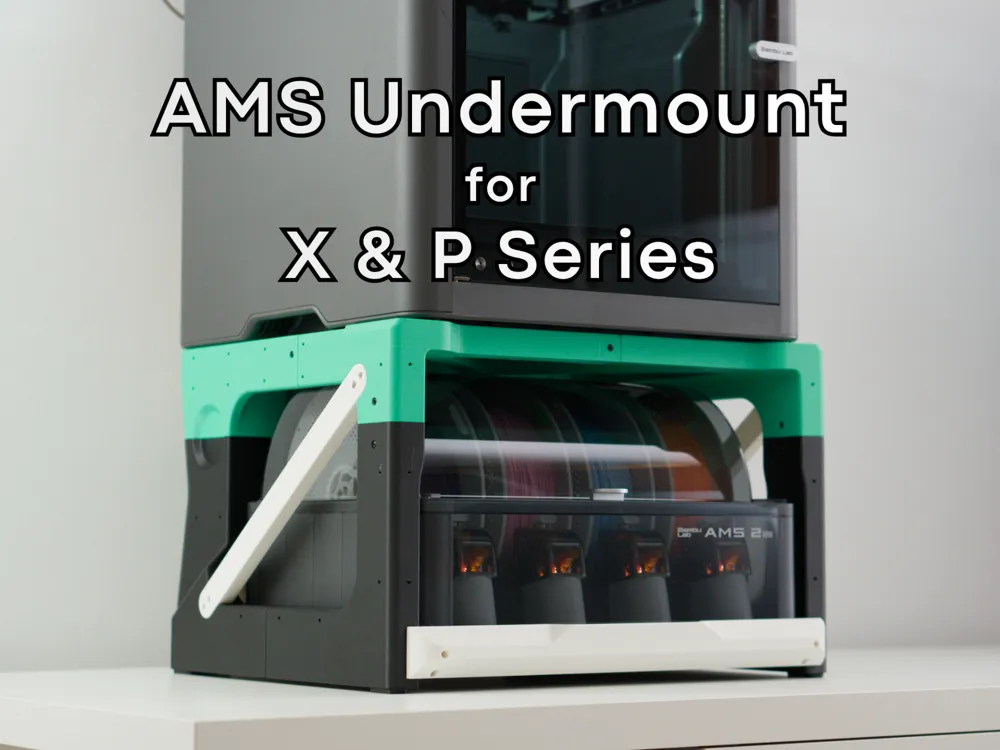
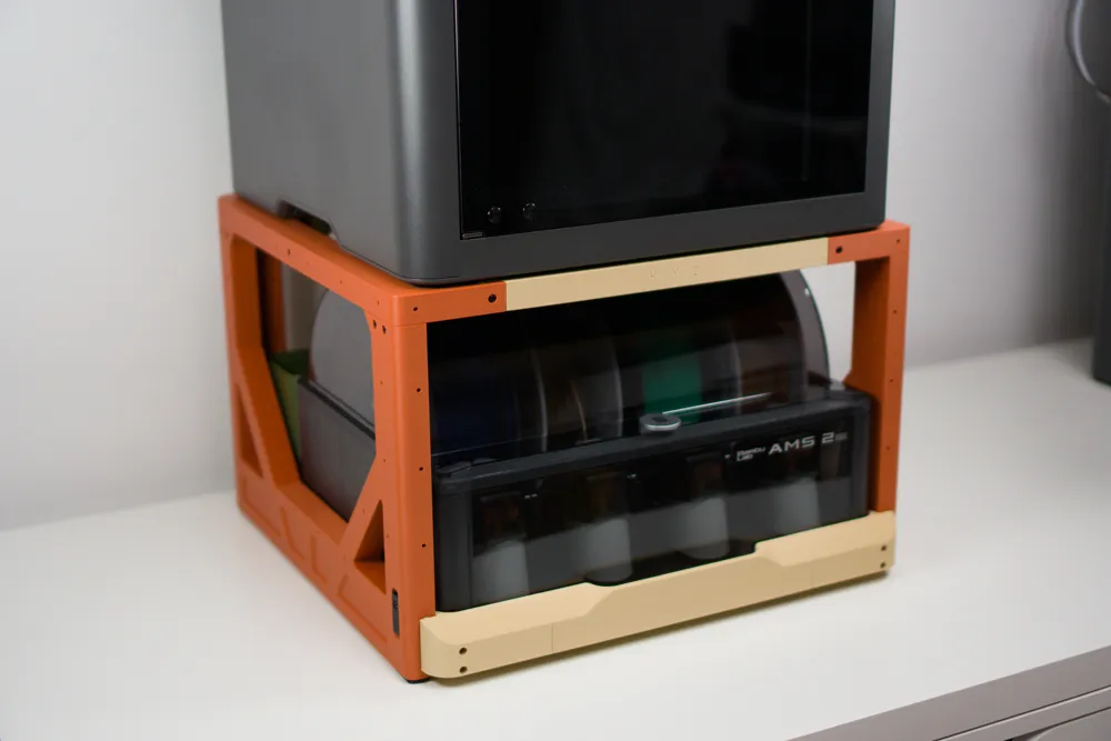
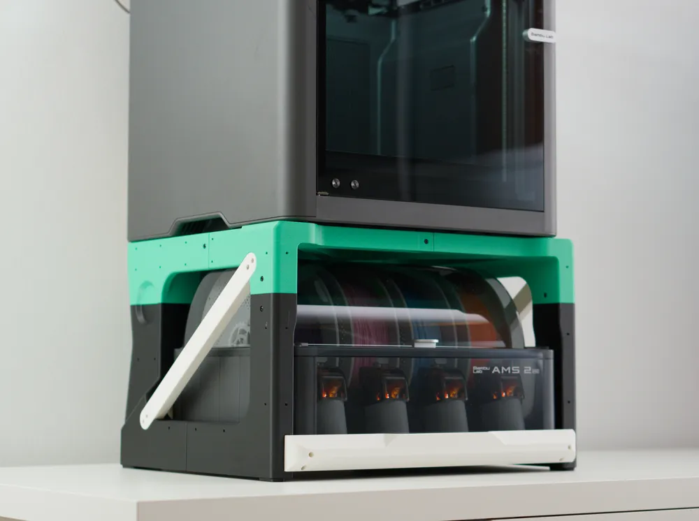
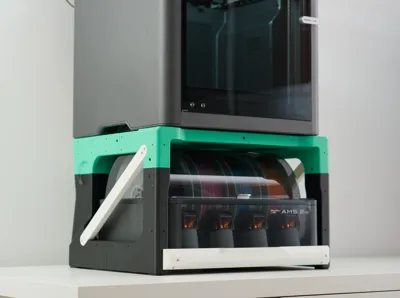
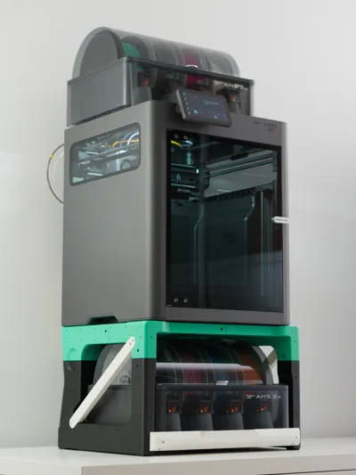
AMS Drawer for X/P-Series with Printed Slides
Print Profile(3)
Bill of Materials








Description
Introduction
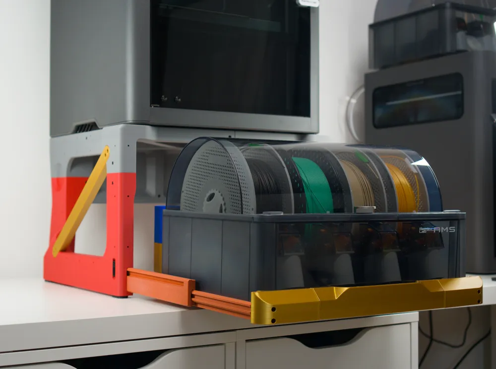
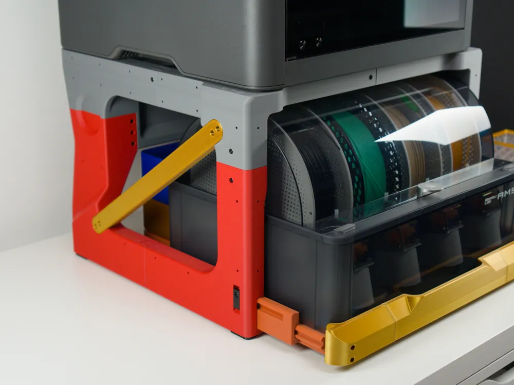
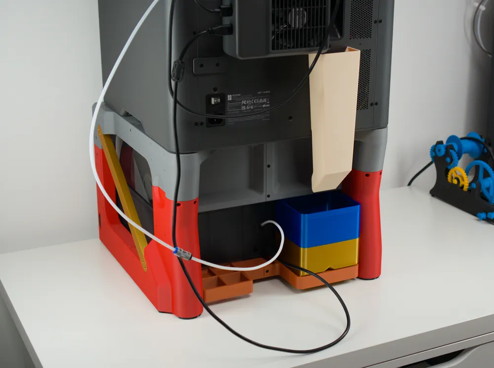
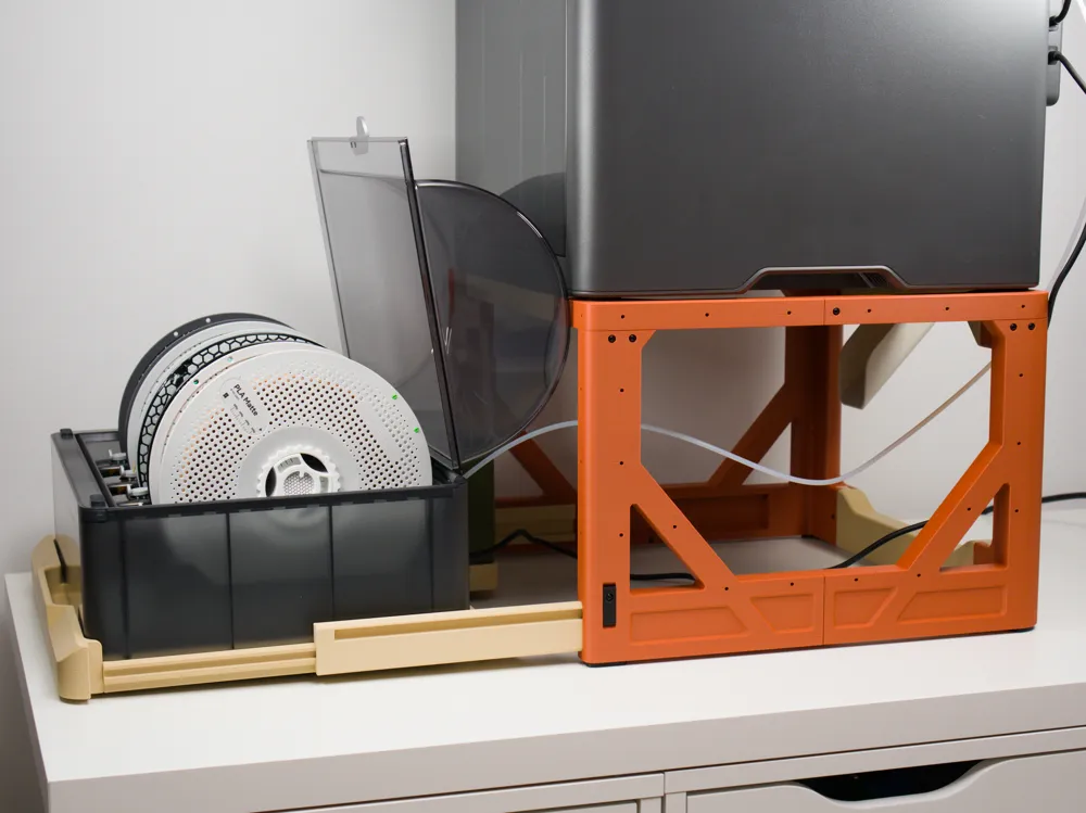
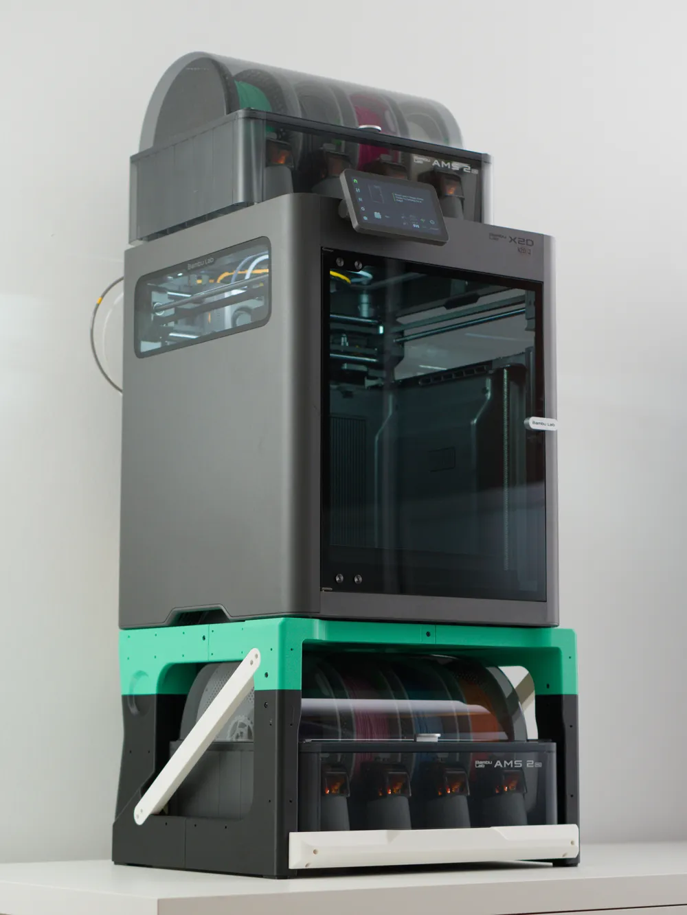
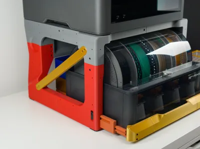
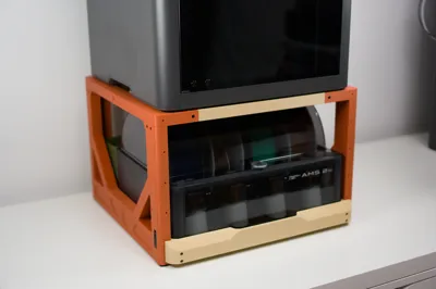
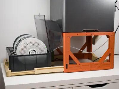
This lets you put your AMS on drawer slides under your X/P series printer and is for you if:
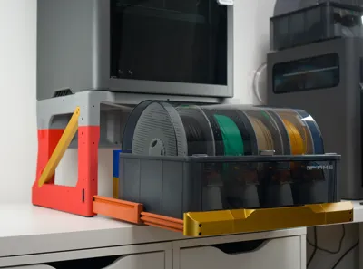
- You want easy access to the top for maintenance and TPU loading,
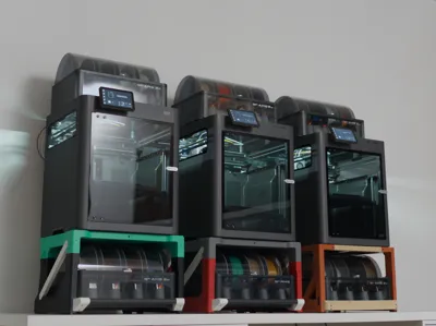
- have 2 AMS's and want a more compact setup (to make room for more printers!),
- you regularly insert magnets or bearings in prints with pause-at-layer and would like easy top access or
- you want to bring the print bed more to eye-level so you can stand there and watch.
I made a short video here as a quick intro:
AMS Undermount for Bambu Lab X2D (Version 1.0)
Vibration test:
AMS Undermount v2.0 Vibration Test
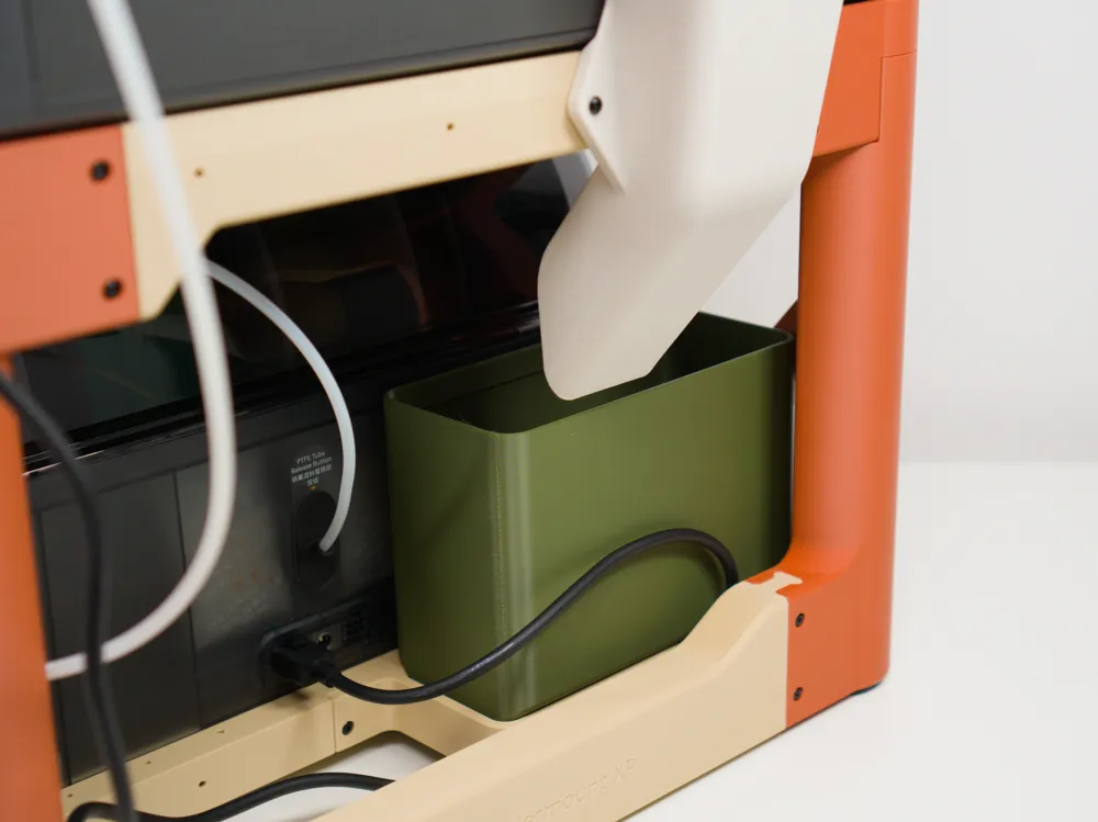
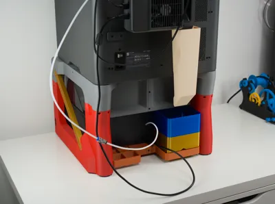
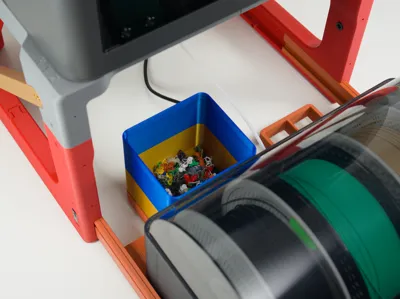
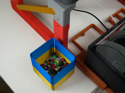
Version 2 is 275mm high and will raise your printer by 273mm. It is 427mm wide and 453mm deep including the handle and poop chute. Note that X2D and P2S printers will need more depth for the exhaust fan exit.
If you don't mind sourcing some hardware would like to use steel drawer slides or a tube handle for a premium feel, check out this collection for all related conversion kits and future add-ons.
Printer Compatibility
This is compatible with:
- X1/P1 series printers and
- X2/P2 series printers
They have slightly different external geometry, but the foot spacings are the same.
If you are looking for one for your A2L, I made one here! (Printables Store)
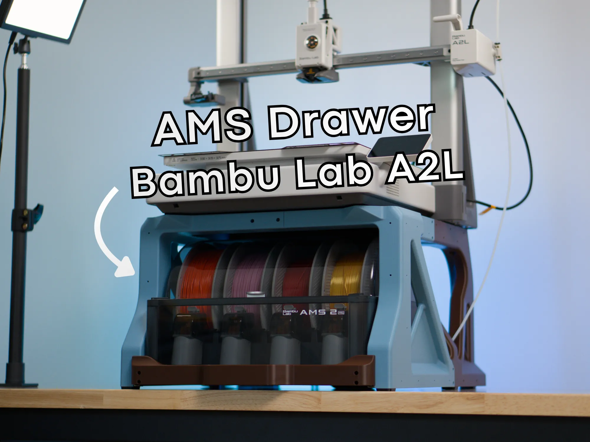
If you are looking for a stand-alone AMS stacking solution, I'm working on it! Follow my profile so you don't miss it.
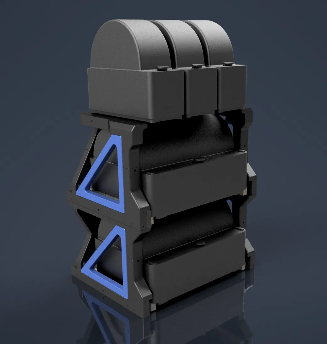
AMS Compatibility
This is compatible with
- AMS 2 Pro (both 4 and 6 rib designs)
- Original AMS (both 4 and 6 rib designs) - note that some versions of the original AMS may need some small sections of material removed - please see the Assembly and Installation section.
- AMS HT is NOT compatible (but you can attach one with this!)
Note: one user on Reddit commented that, with the filament track switcher in-line in the standard position (sticking out to the right), combined with the longer PTFE tube, they were getting some feed errors due to the feed resistance. I do not get any errors without the track switcher and another commenter said their setup with a track switcher is fine. If you would like to use a track switcher, you could test out the filament path first, without printing anything.
Gallery
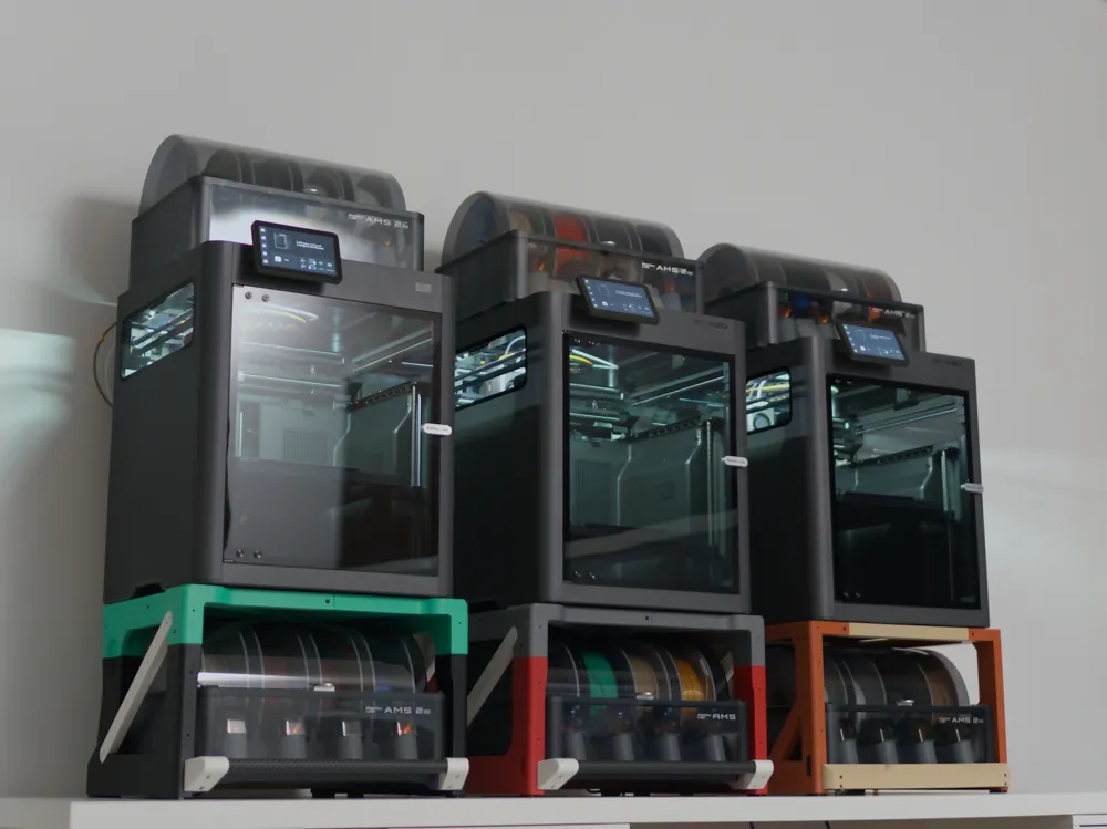
First full make by @alaswadh71! Much happier colour scheme than mine. Printed slides with carbon handle. 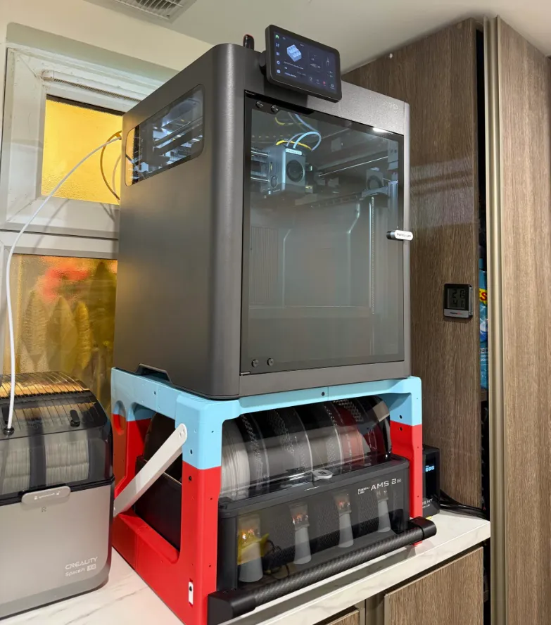 | By @atom631, classy subtle colours with 35mm steel slides and carbon handle. Printer on Hula feet. 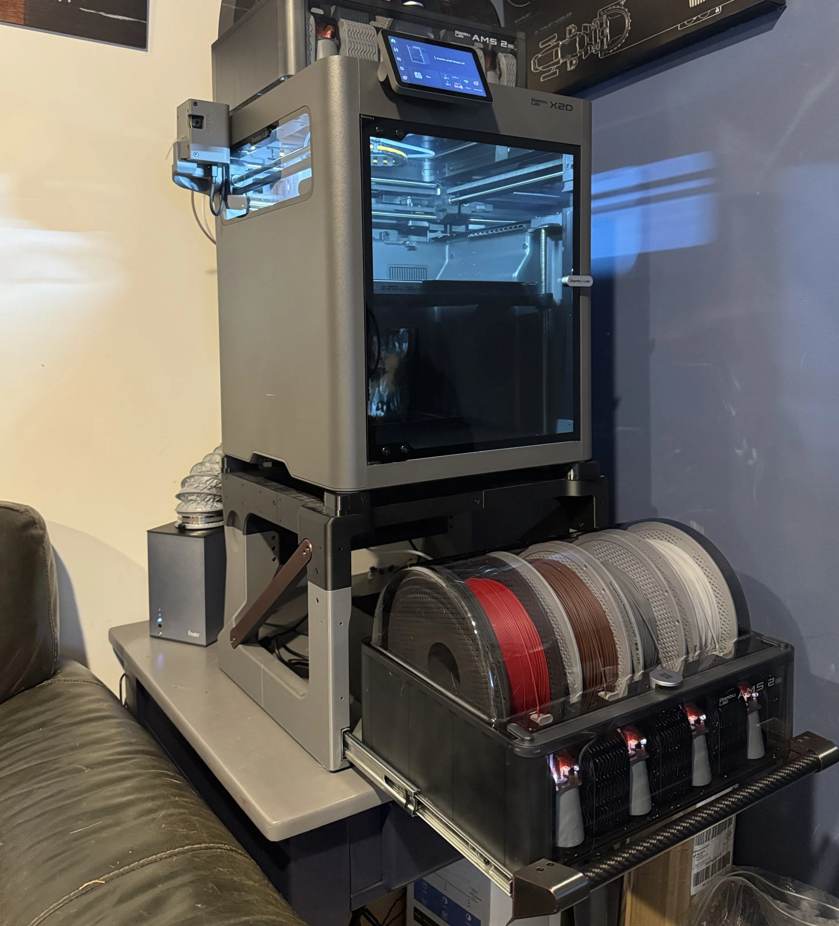 | By @Redred85, all black! 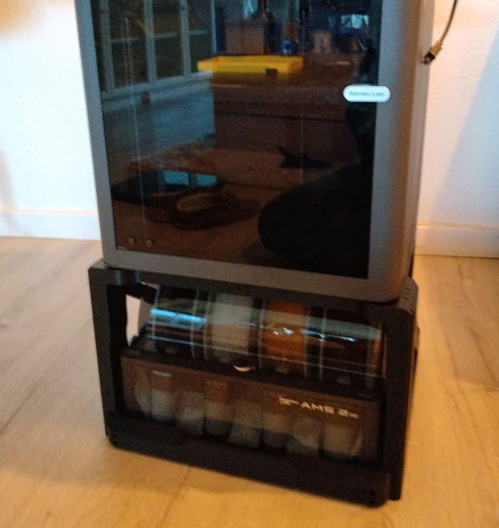 |
By @user_3977378054 from Korea, with an Original Prusa colour scheme! 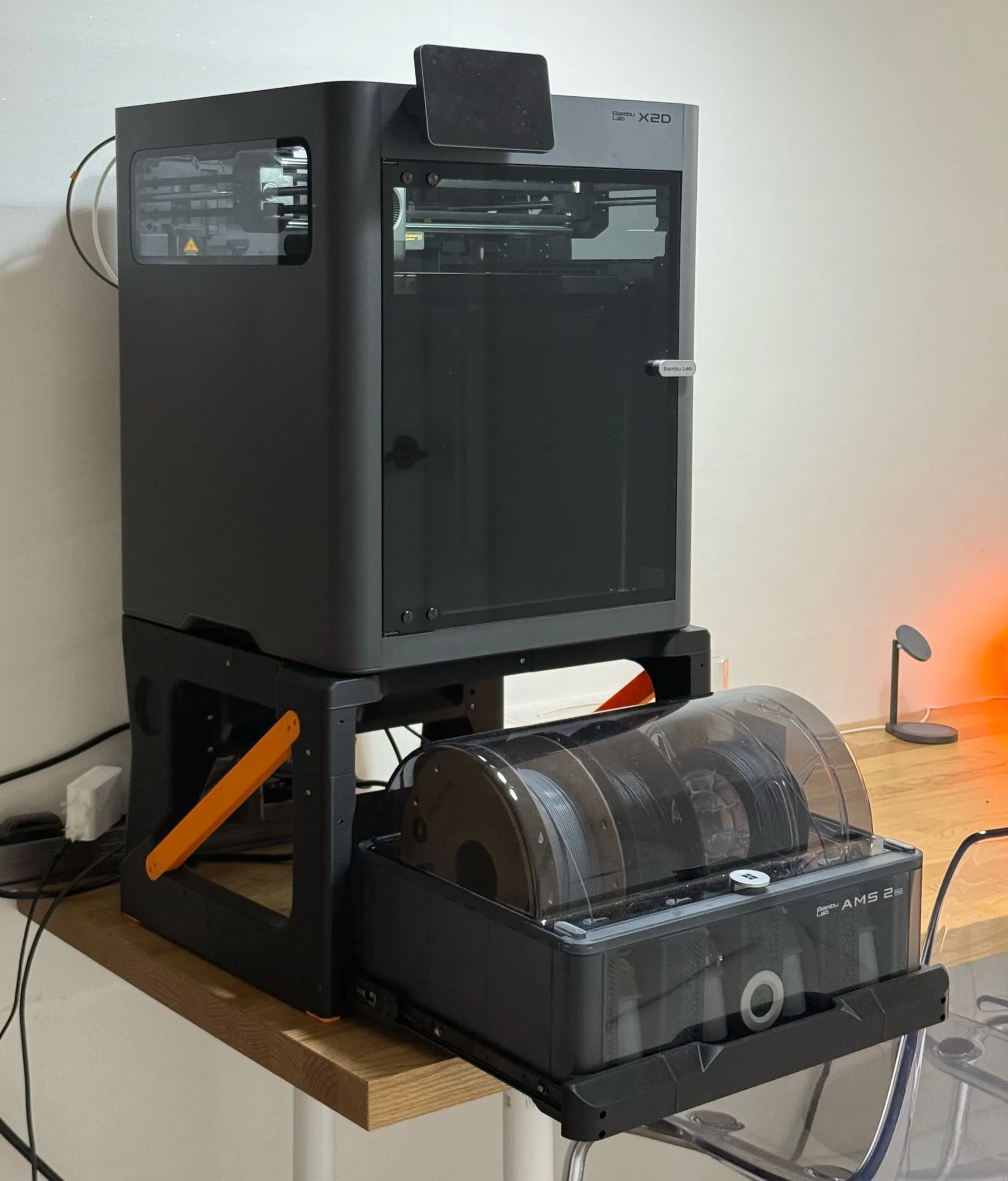 | By @CrownSeven with a stormtrooper theme, X1-Carbon with anti-vibration feet and original AMS. 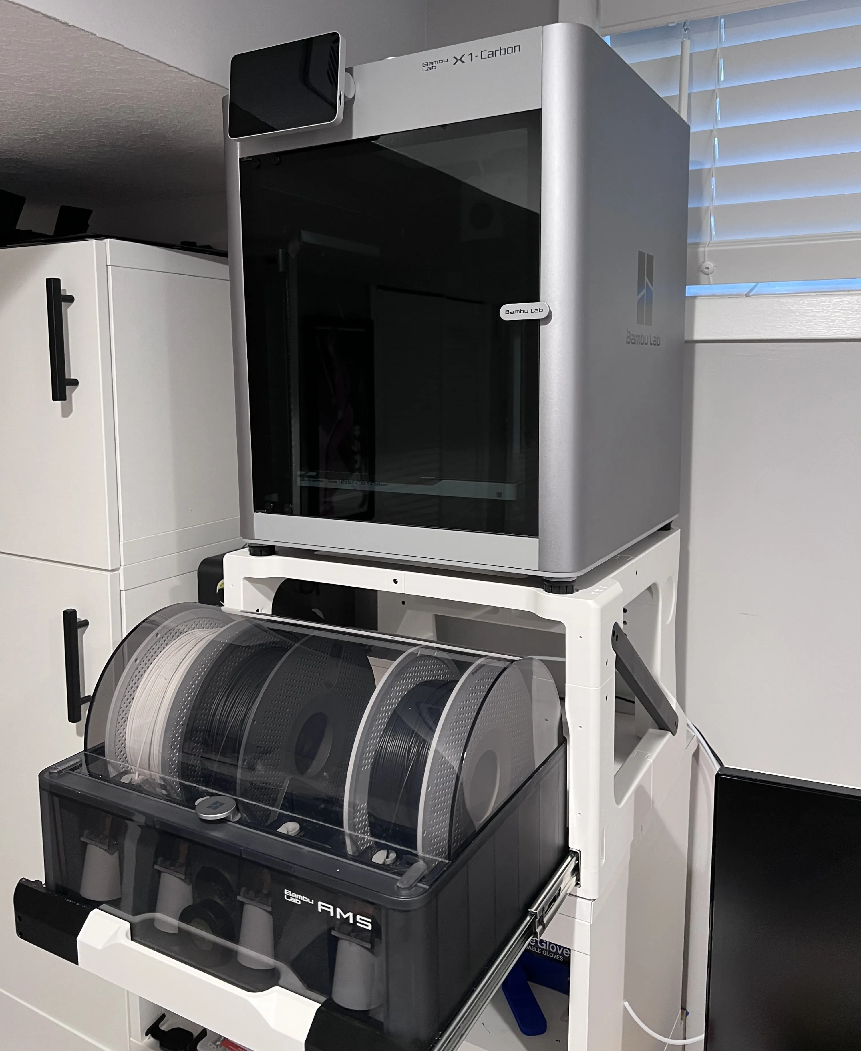 | Reverse B&W one by @newyorican89, P1S with anti-vibration feet and original AMS. 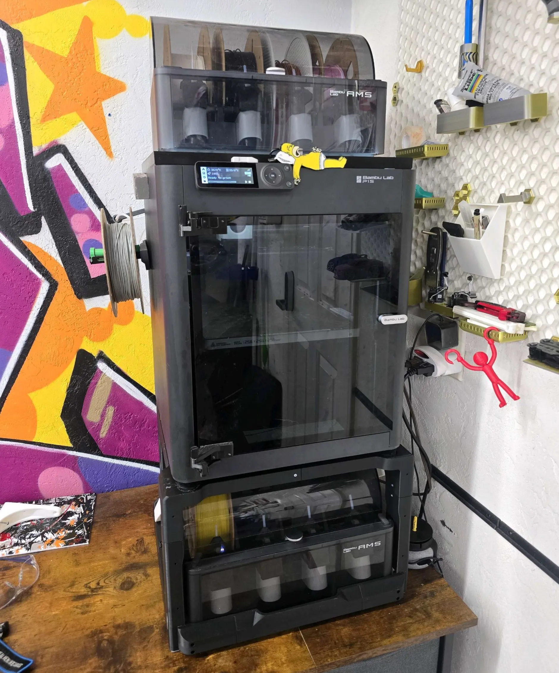 |
By @geekt.art with printed slides and a plate holder, the AMS lid no longer hits the spool rack above :) 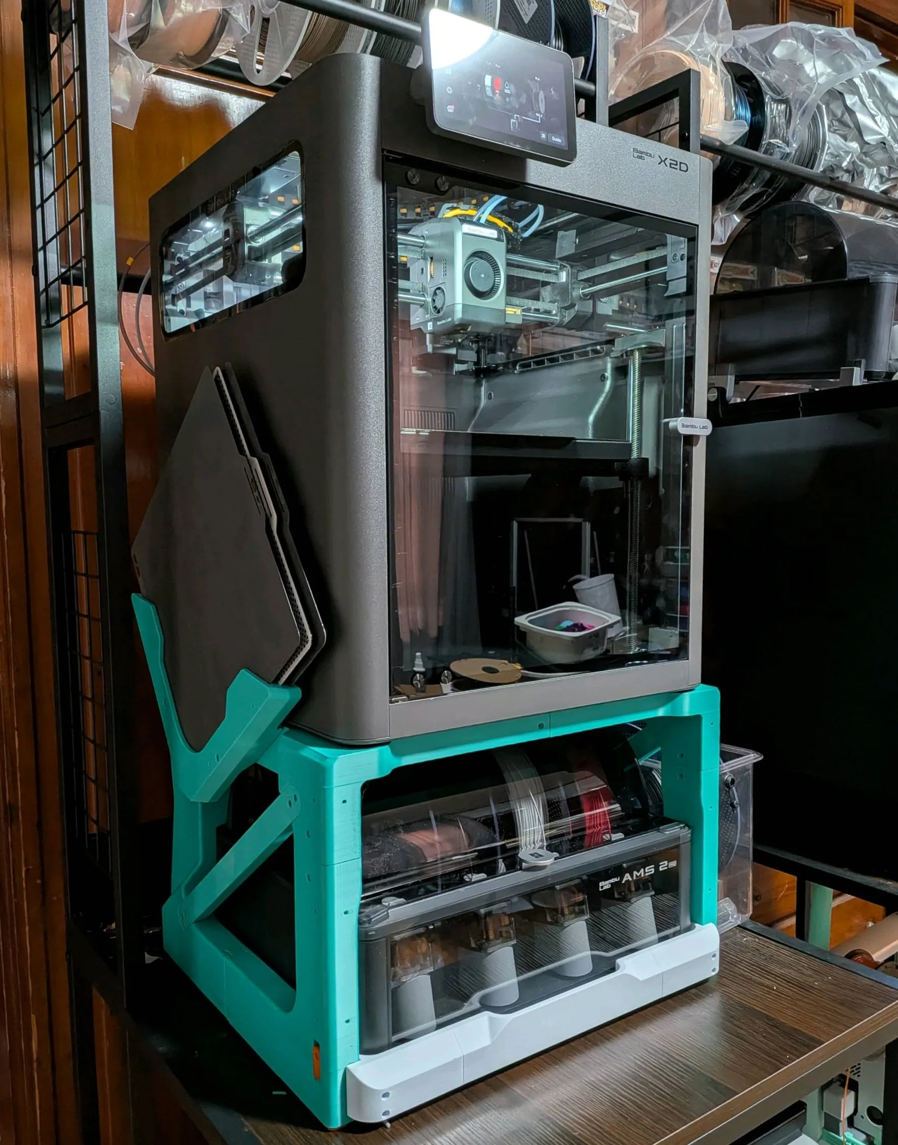 | By @welker1 - with the AMS HT sidecar. 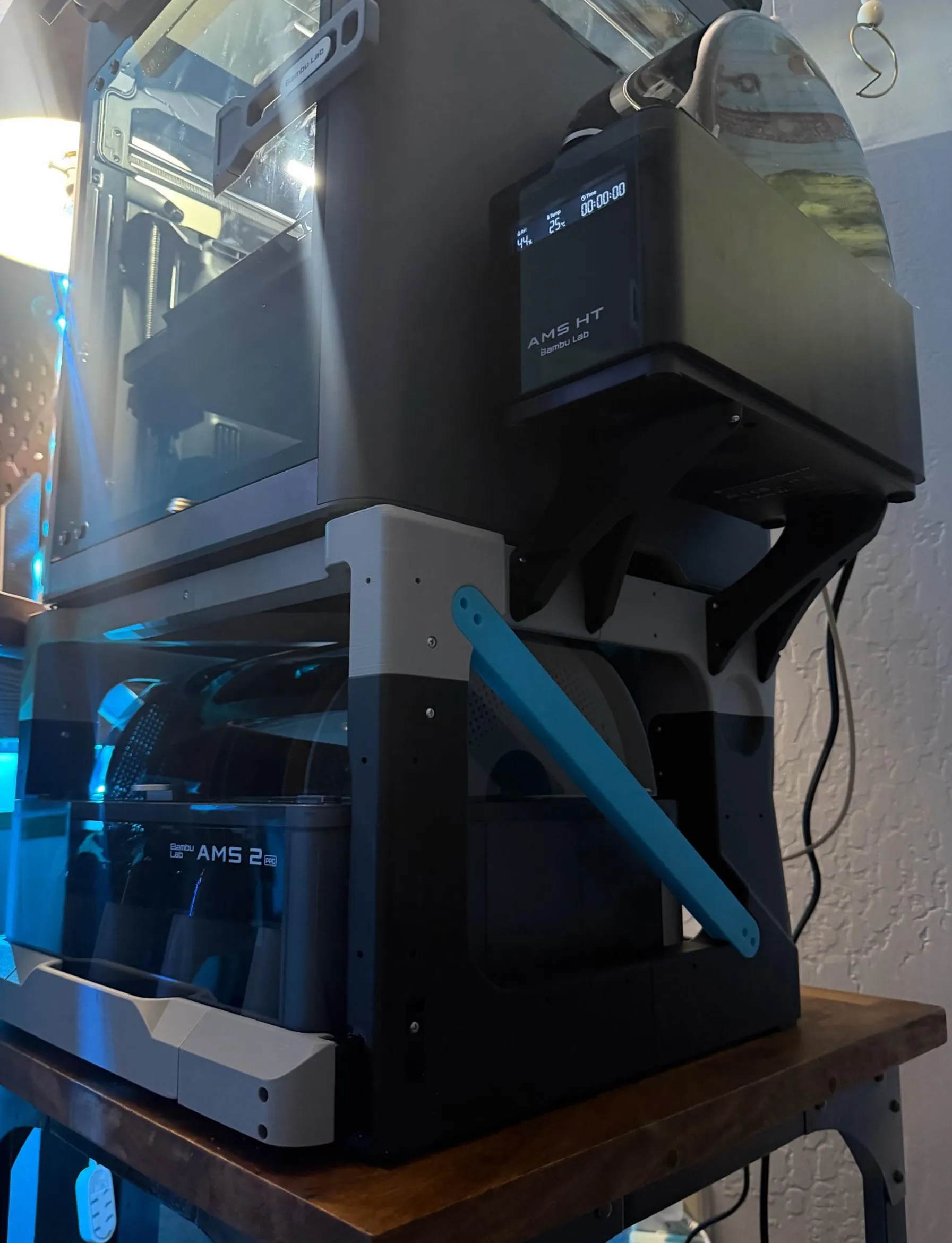 | By @RuneMasterBy made from PETG-CF and ASA to help AMS access in a tight space. 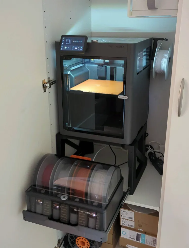 |
By @zergar with Fiberon PET-GF grey upper frame, PLA-CF for the dark red and black. 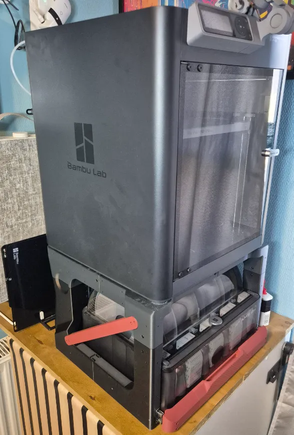 | Please post your builds and I'll put them here! |
Difficulty
This project is for people with intermediate experience in 3D printing. What can make this challenging are:
- Basic filament tuning recommended for every spool of filament used
- AMS required for multi-material interface layer supports (you do not need a multi-nozzle printer as there are very few filament changes)
- Some minor post-processing (sanding/trimming) may be required
- Parts are large and if ABS, ASA or other non-fibre-filled high temperature materials are used, you will need to take shrinkage into account. There are enough clearances in the design such that PETG will work without shrinkage compensation, but it is still a good idea to do it.
Even if you are fairly new to 3D printing, this could be a great learning opportunity if you take your time reading this and do your research on each tuning and part.
Filament
The filament choice depends on your use case. For example, If you print in a warm environment with the heated chamber on and an AMS 2 Pro below with the drying on, the top half of the frame can get quite warm. The top front part of the frame can creep under the printer weight and sag over time. However, if you mostly print PLA in a cool garage, PLA is likely to be fine for you. Here is a selection guide:
| Material | Use Case | Notes |
|---|---|---|
| ABS-GF/CF, ASA-GF/CF or other low-warp, heat-resistant and creep-resistant material | Best choice for the frame, especially the top half. Overkill for the slide assembly and slides. | |
| Regular ABS/ASA | Also a great choice for the frame. | Heated chamber required to print (relatively) warp-free parts. Shrinkage compensation required. |
| PETG/PETG-CF | Good choice for the frame. | PETG is generally less rigid. Add extra walls/tops/bottoms to compensate for the low stiffness. |
| PLA | OK for the frame in cool environments. Good for slides, slide assembly and frame braces as these only see temporary loads. | |
| TPU 90A or 95A | Use for the feet and the printed slide locks. | |
| PLA Silk, PLA-CF and “ABS+" | Do NOT use for printed slide rails (inner and outer). | Weak layer adhesion. |
Please feel free to post your print profile. Add lots of pictures and a detailed description please! It will help other people decide which one to use.
Hardware for Assembly
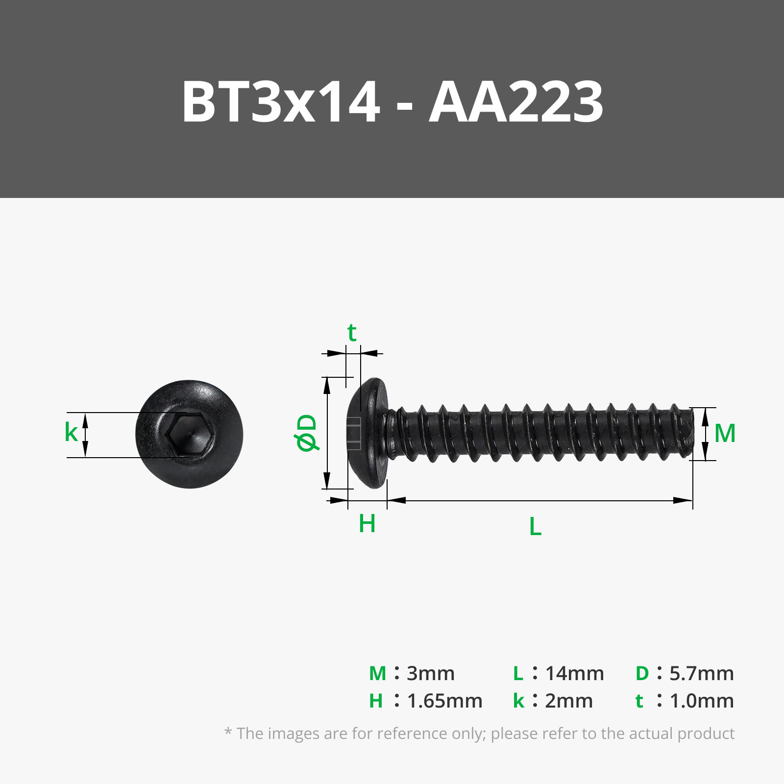
Only one type and length of screw is needed: BT3x14 BHCS Self Tapping Screw (AA223). This is a 3mm diameter, 14mm long screw designed for plastic with coarse deep threads that cut into and grip well onto holes in plastic. They are not expensive extremely easy to use as you don't need to embed heat set inserts or seat little M3 nuts. They also make the printed parts simpler and use less material than trying to use printed fasteners.
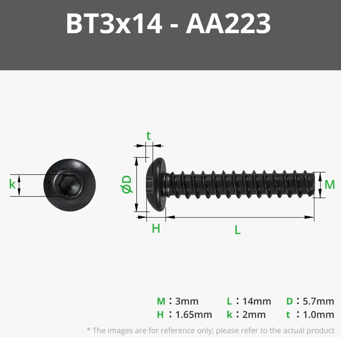
Alternatives:
- If you have 12mm or 10mm screws or the socket head style of BT3 screws, they will be OK too.
- If Bambu doesn't ship to your country, the key words to search are “3mm self-tapping screw hex socket”. Try to get some without a pointy tip as they have a slightly longer usable thread length and a head height of 2mm or less. I found some products on AliExpress (Listing 1, Listing 2, Listing 3) which look promising, but I have not tried them.
- Do NOT use countersunk screws as most holes in the design are parallel to the print bed plane and the screws can split your layers if you're not careful with tightening.
You will need:
- 49 for the frame assembly
- 14 for the slider assembly
- 4 to attach the AMS to the slider
67 screws total (although, this number seems to change every time I count them!)
In the bill of materials, I have put 4 packets of 20 screws as I will be using these screws for future add-ons. Always get extra screws! I suggest getting some 12mm and 10mm ones too, to have on-hand.
You will also need
- Plastic-safe lubricant for the printed slide rails
- 4 D6x3 magnets (smaller/thinner ones also work if you make adapters for them)
Parts for Installation
You will need a longer PTFE tube than typically supplied with printers (or a coupler to connect two shorter ones) as the AMS travels forward and back. The AMS travel length is 360mm. This is linked in the bill of materials.
You may also need a longer 6-pin AMS connector depending on your AMS arrangement. With the X2D/P2S, the standard cable that comes with the AMS 2 Pro is long enough to go from the printer's buffer to the AMS and allow the AMS movement.
If you intend to use this with an X1 or P1 series printer, use the anti-vibration feet to limit the vibration transmitted to the structure. (X2 and P2 printers are already equipped with these.)
Print Settings
General Tips
- Flow rate calibration is highly recommended for every spool you use! Many clearances in the design are 0.1mm. For proper fit, the parts should not be under or over-extruded. The dovetail joints should slide together easily.
- Shrinkage compensation (applied in the filament settings - please read the wiki article)
- This is a must if you are using ABS, ASA and other non-fibre-filled high temperature materials as the overall assembly is large and can affect overall dimensions by 3-4mm.
- For PLA/PETG/ABS-GF/etc., it is still recommended but not necessary if you're only using these materials. There are enough clearances in the design so that the whole thing can be 1-2mm smaller.
- If you are combining high shrinkage material parts with low shrinkage material parts, you should compensate for shrinkage on both or slightly under-compensate the high-shrinkage parts so that they fit together good.
- The compensation does not need to be super accurate but do not use a 20mm cube to calculate shrinkage like the wiki says - that is too small and your results will be affected by other things like flowrate. Use at least a 100mm bar or measure some larger things you already printed to get a better indication.
- If you do not want to go through the trouble of finding the values, these factors should be adequate:
- PLA/PETG/ABS-GF/ASA-CF/similar: 99.8% in XY
- ABS/ASA: 99.5% in XY
- Any support material will need the same shrinkage factor applied to it, so it prints aligned to the main part.
- Dry your filament (even PLA) to minimise risks with dimensional accuracy.
- Aux fan OFF if you've had issues with part warping. Don't worry, all of the overhangs are super easy.
- Use an AMS to print a multi-material support layer for clean bridges and overhangs. It is not required everywhere - just on the areas painted in the print profile for the 8 frame parts. I used support material but using, for example, PETG as an interface layer for PLA should be OK as there are built-in supports to prevent curling-up of corners. PETG would be easier to peel off too as it sticks to itself whereas the support material falls apart.
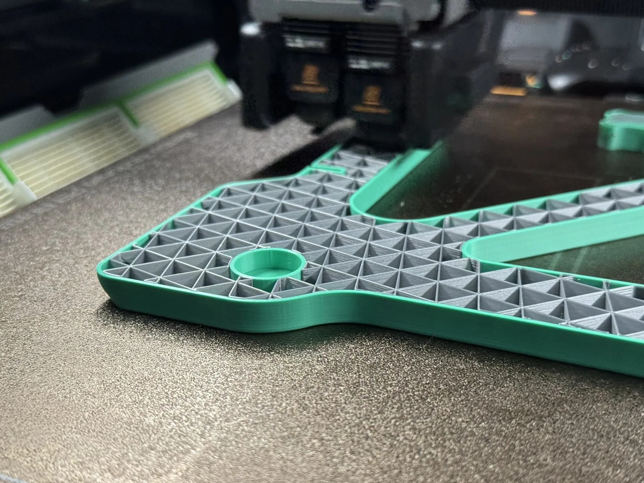
Pro tip! If you're running out of a certain colour but you have 2 nozzles, you can dump a different colour into the infill of a compatible material to save your main material. Note that if the main material has a shrinkage factor applied, the infill material will need the same shrinkage factor, so it prints in the right place. In the example below, I'm using a cheap ABS to fill a nice ASA part:
Specific Settings
These are the settings I use and are quite conservative and a little slow for a clean print with sharp corners, it's a balance between Bambu's “High Quality” and “Standard" profiles. Feel free to deviate as you see fit. Although these are already applied to my own print profiles, if you download it and change printer, some of these may get overwritten so I will list them here.
Speeds
- Outer wall: 80 mm/s
- Inner wall: 150 mm/s
- Top Surface: 150 mm/s
- Everything else: default for your favourite profile
Accelerations
- Normal printing: 4000 mm/s²
- Outer wall: 2000 mm/s²
- Inner wall: 0 (same as Normal)
- Top surface: 2000 mm/s²
- Sparse infill: 8000 mm/s²
- Everything else: default for your favourite profile
Strength
Parts are designed for a 0.4mm nozzle printing 0.2mm layer heights.
| Wall loops | Top/bottom shell layers | Infill |
|---|---|---|---|
Front crossbar of frame | 5 | 7/5 | 15%, your choice of pattern |
Printed Slide rails, outer | 6 | 7/5 | 15%, your choice of pattern |
Printed Slide rails, inner | 4 | 7/5 | 15%, your choice of pattern |
TPU feet | 6 | 6/4 | Any |
All other parts | 3 | 6/4 | 12-15%, your choice of pattern |
If you use PETG, add more material to compensate for the low stiffness.
Supports
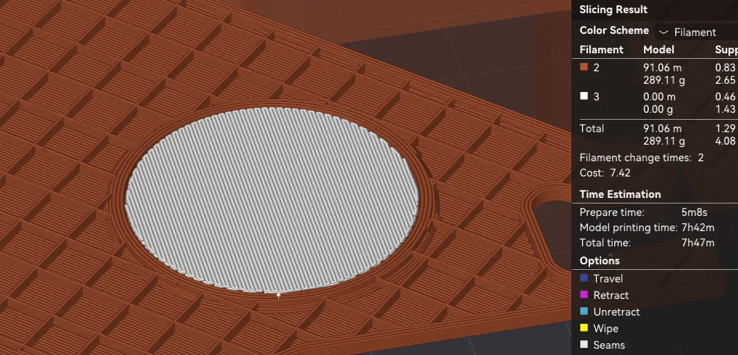
The 4 upper frame parts have cylindrical recesses where the printer feet sit in. These can be supported with normal supports, with or without support material. My PLA profile uses Support for PLA interface layer for a clean finish but that isn't so important as you won't see it. For my ASA and ABS-GF prints, I did not use an interface layer of a different material (just a 0.2mm gap).
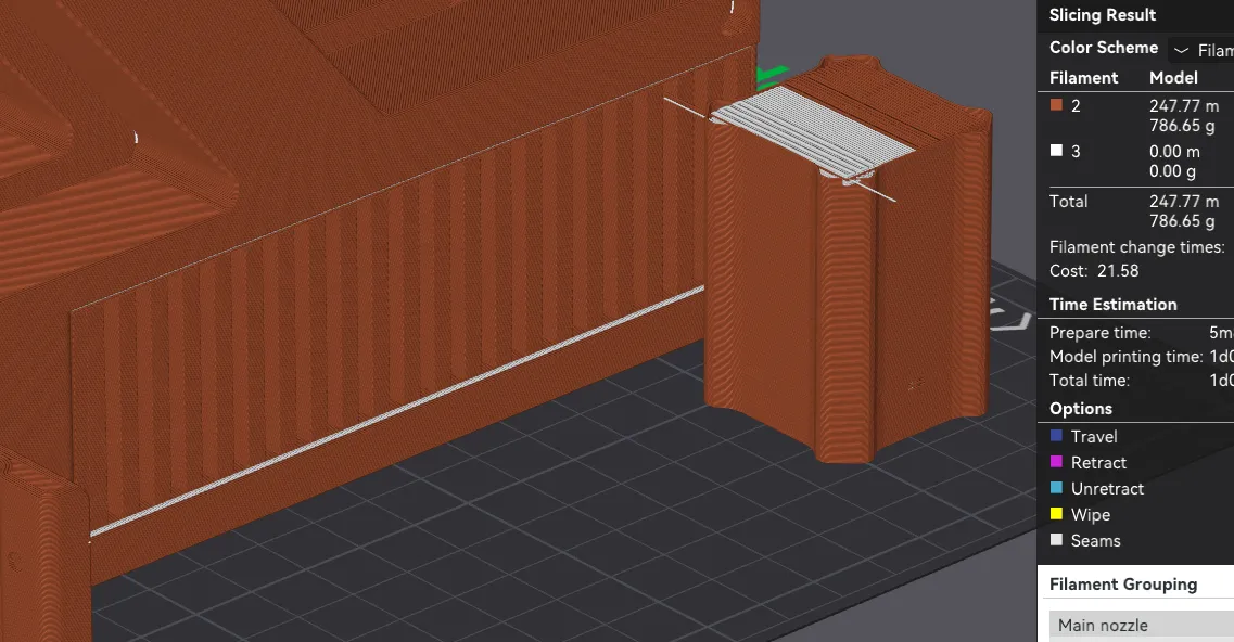
The 4 lower frame parts must have the printed slide rails supported with an interface layer using support material with zero gap for smooth slide movement.
Support is not needed anywhere else and no other parts need supports.
Note that the variant that only supports steel slides does not need support material on the lower frame parts:
For printed rails (also compatible with 35mm steel tracks), this is the model on this page 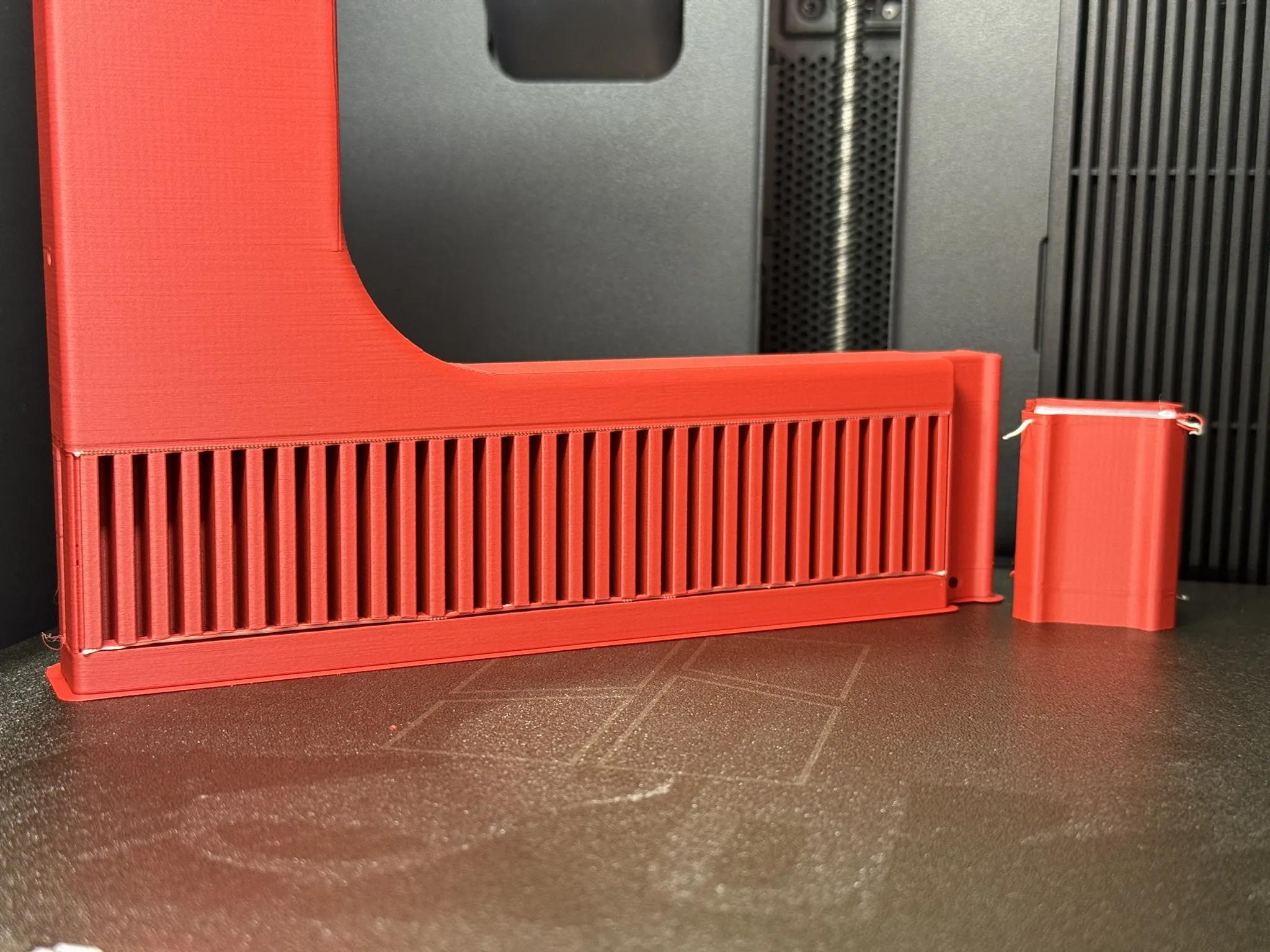 | For steel rails only, this is the lower frame variant available here, not on this page 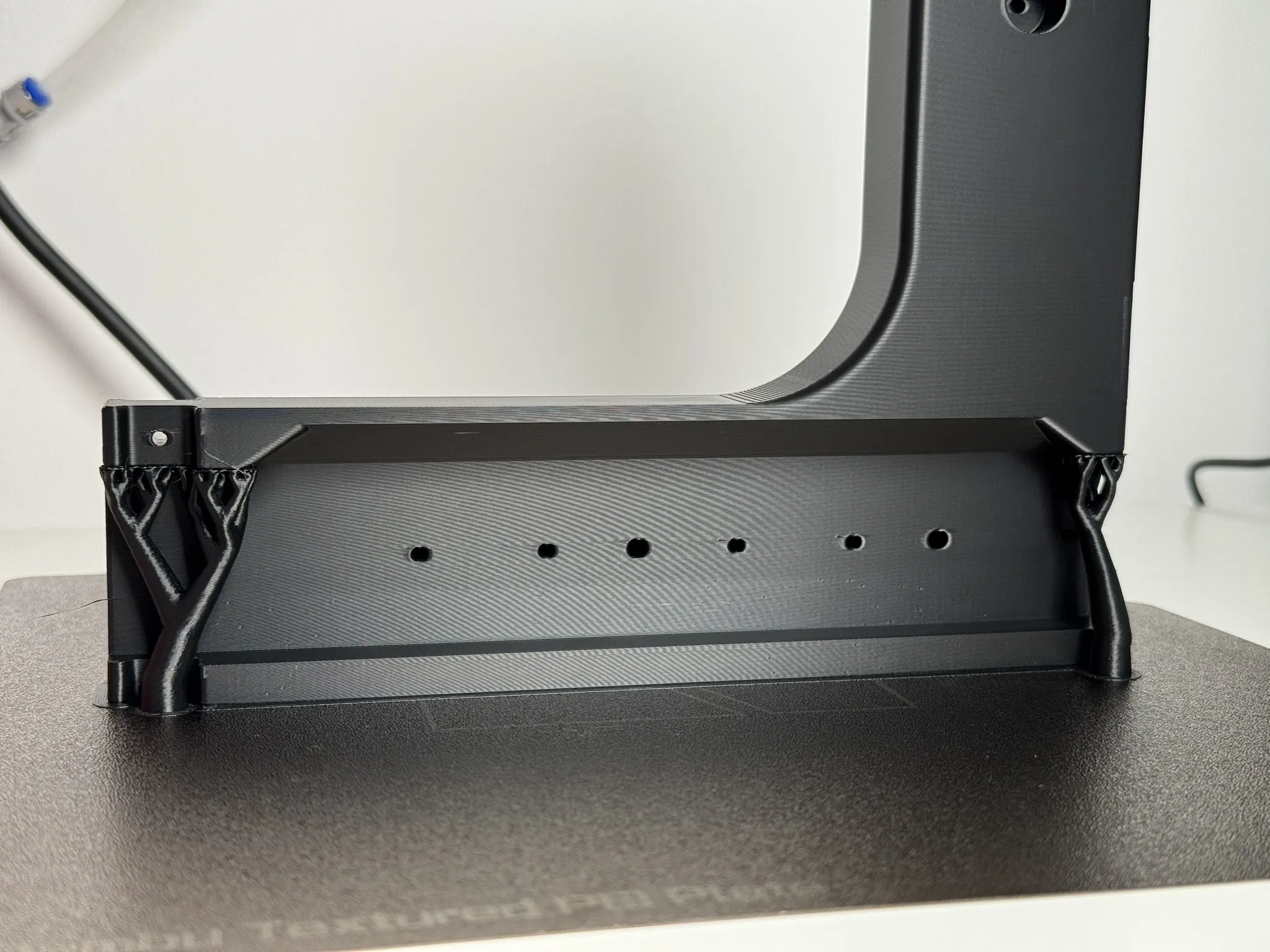 |
Pre-flight check
Before printing the big parts, check:
- Supports on where needed
- Seams hidden
- Shrinkage applied (you can see that the part in “Preview” tab is larger than in “Prepare” tab)
(I list these because I've forgotten each of them at least once!)
Bonus tip
Once for each printer you use, watch your first or second layer perimeter loops go down through the camera and see if the bed is moving up and down visibly. If it is, it's indicating that your bed may not be trammed. Tramming is making the bed parallel with the motion system. “Auto bed levelling” does NOT level the bed, it only compensates for an un-level bed. Bambu printers are trammed at factory, but I've had one made on a Monday morning that was not and the rear was 2mm lower than the front which produced a skewed part that did not fit great.
Manual Bed Leveling / Manual Bed Tramming | Bambu Lab Wiki
P2S & X2D Heatbed Manual Bed Leveling | Bambu Lab Wiki
Assembly and Installation
Look, all the screws are the same, you can't screw this up. Most parts are poka-yoke and only fit one way. Just one thing to note if your parts are PLA: screws can get hot while tightening; tighten them most of the way and give them a minute before final tightening.
Slider Assembly
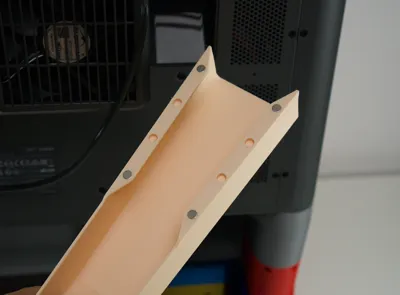
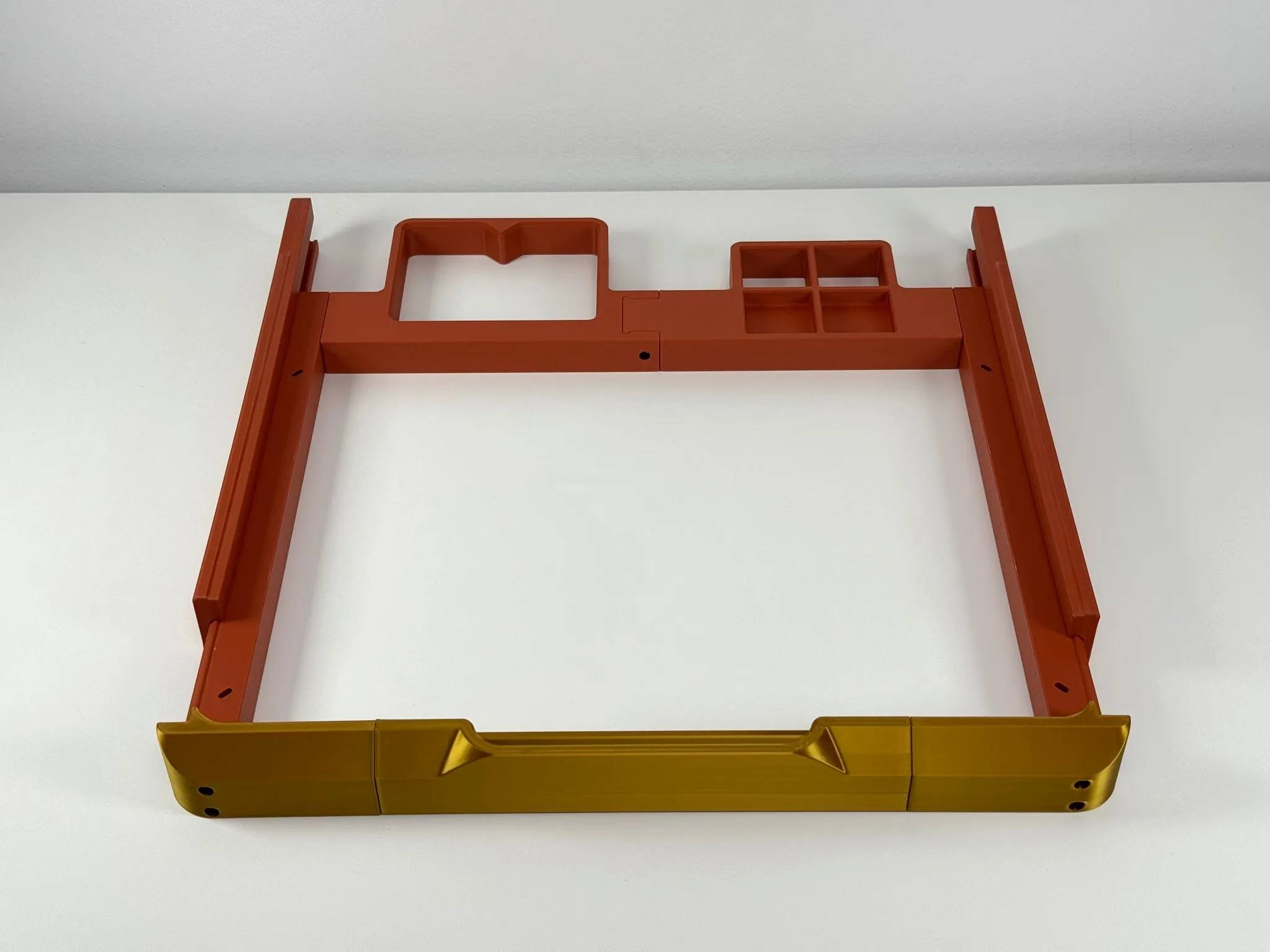
Partially assemble the slide assembly as shown. Don't attach the handle until the outer slides go on. When assembling the handle, you will see that the screw holes are covered with one layer of material to support the counterbore. Just push the screw through, no need to drill it out.
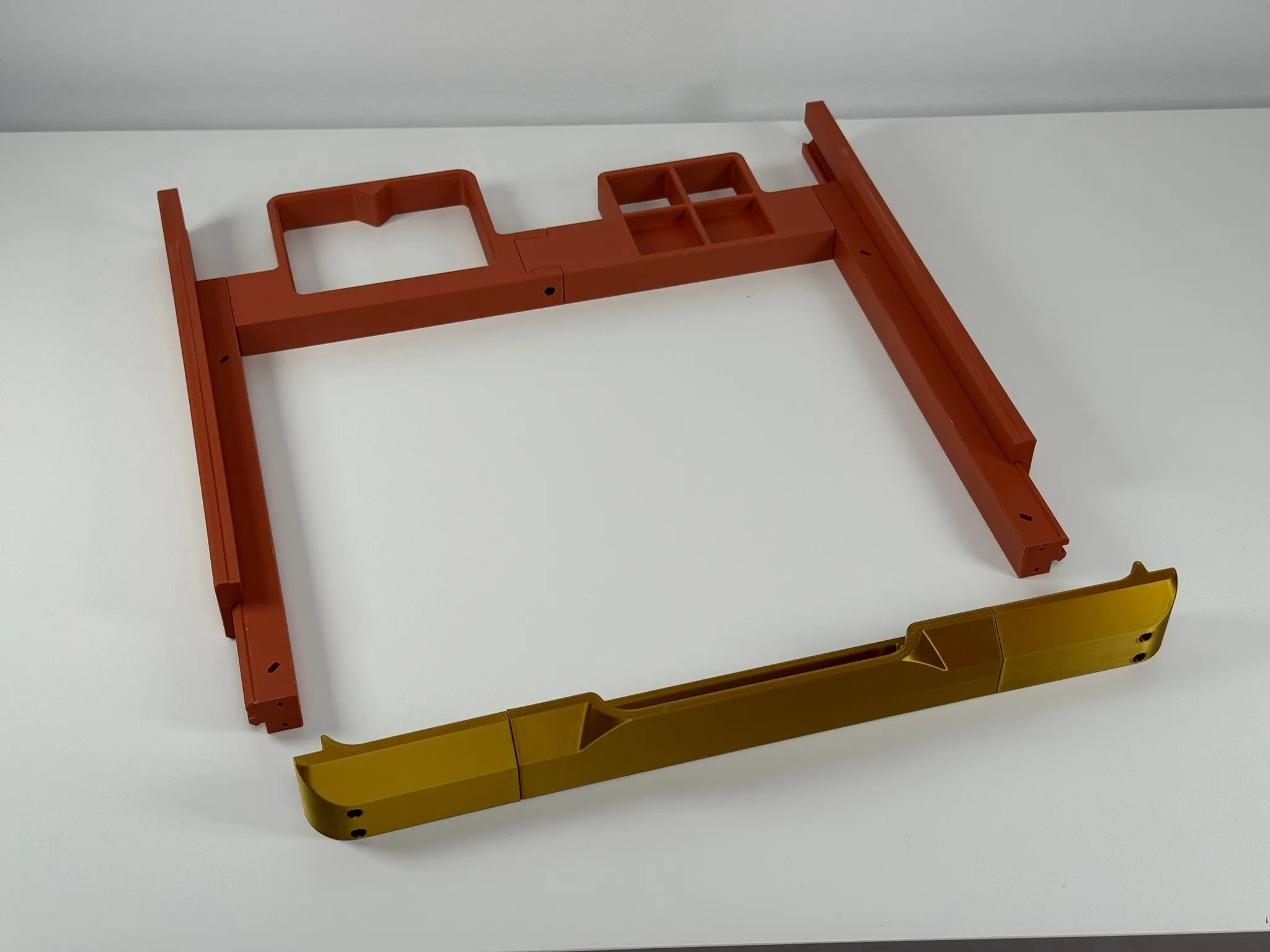
Once it looks like this, attach the handle. Super easy.
Attach the AMS
For some versions of the original AMS, there are some small pieces of plastic that need to be trimmed. This is not necessary for the AMS 2 Pro and some original AMS variants.
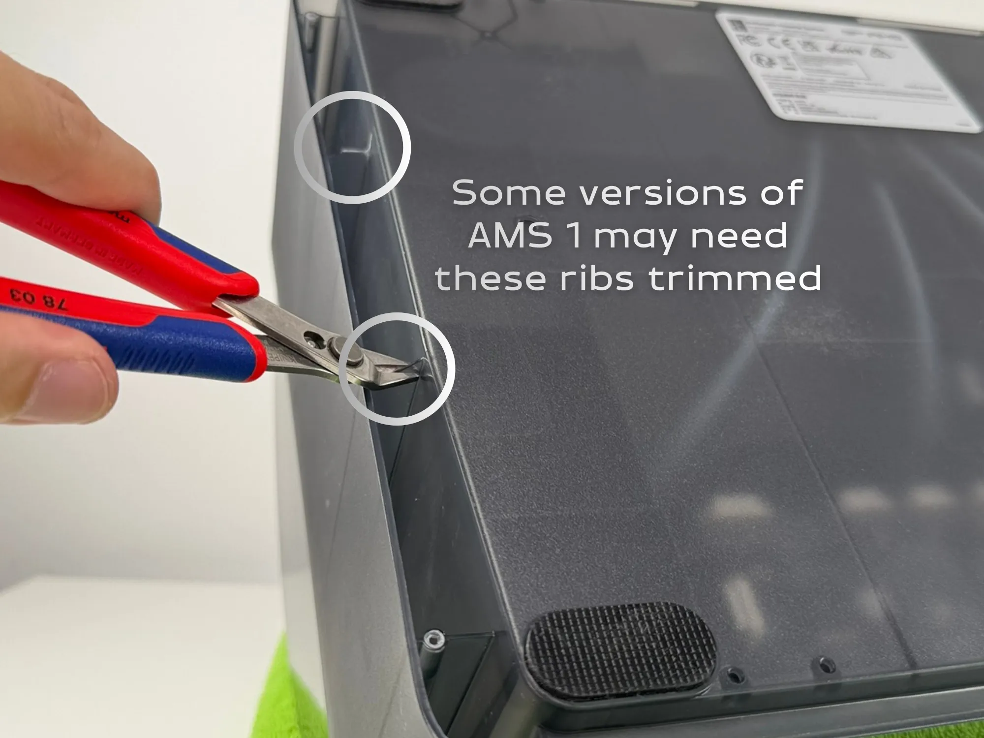
Use 4 screws to attach the slider assembly to the AMS transit screw holes.
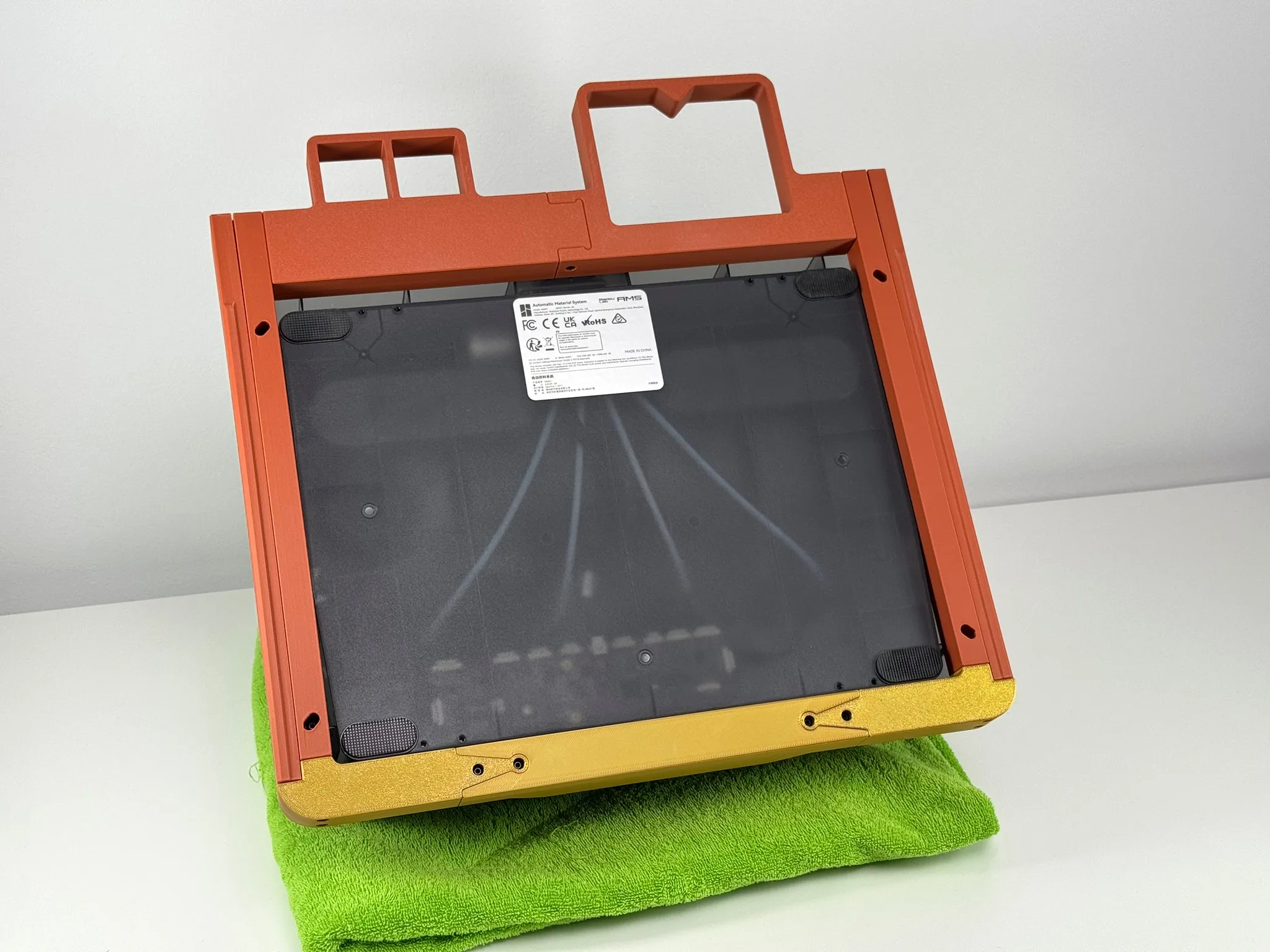
Assemble the frame
Cut-out the built-in supports, remove the support material, and screw the parts together.
(Missing photo…)
Press in the TPU feet. You may need some tape to create an interference fit if they are a little loose.
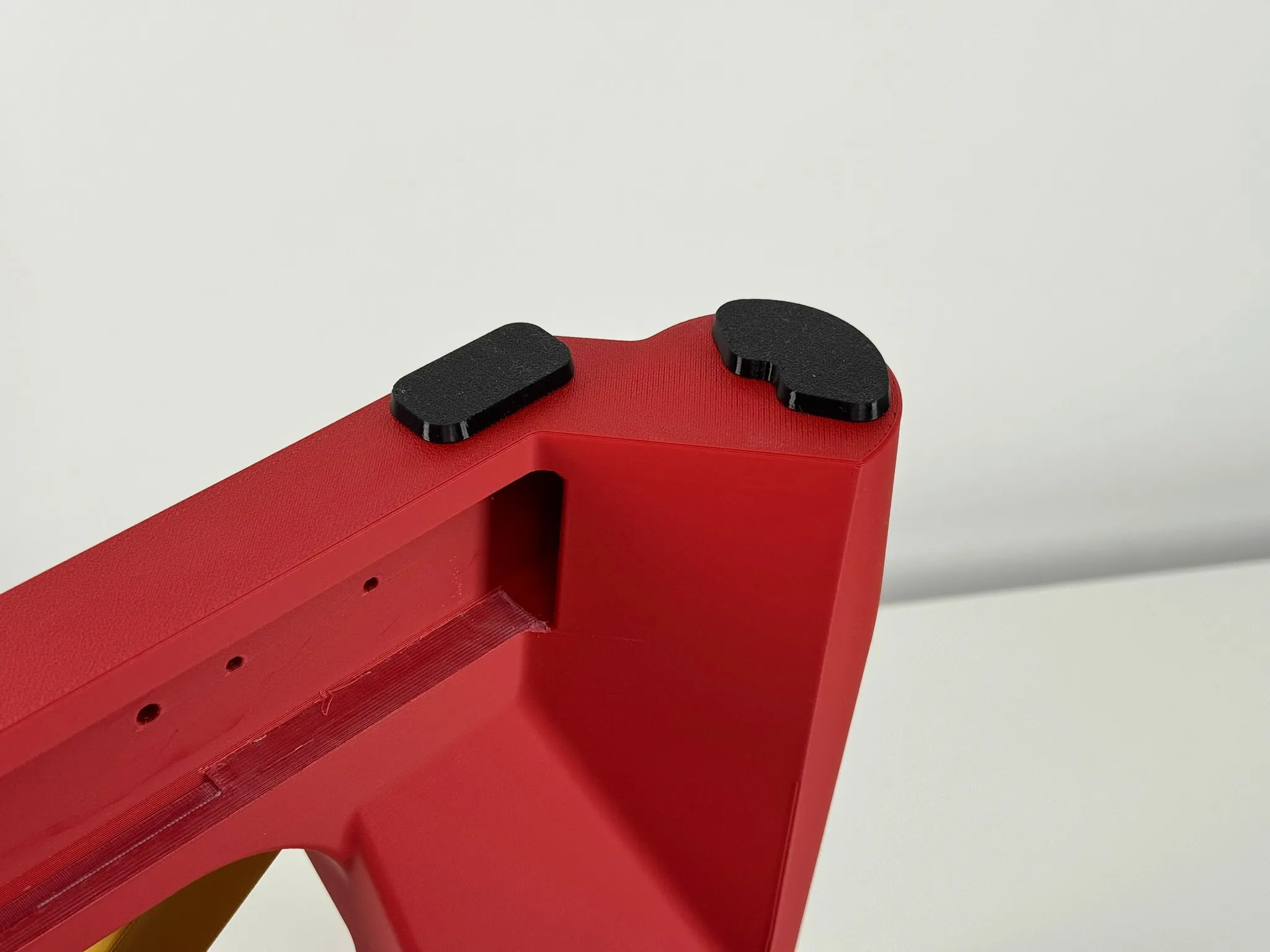
Assemble the slider assembly to the frame assembly
Put everything together. Lock the slides in place with the printed slide locks (The small black parts). Screw them in but not too tightly as to not squish the TPU.
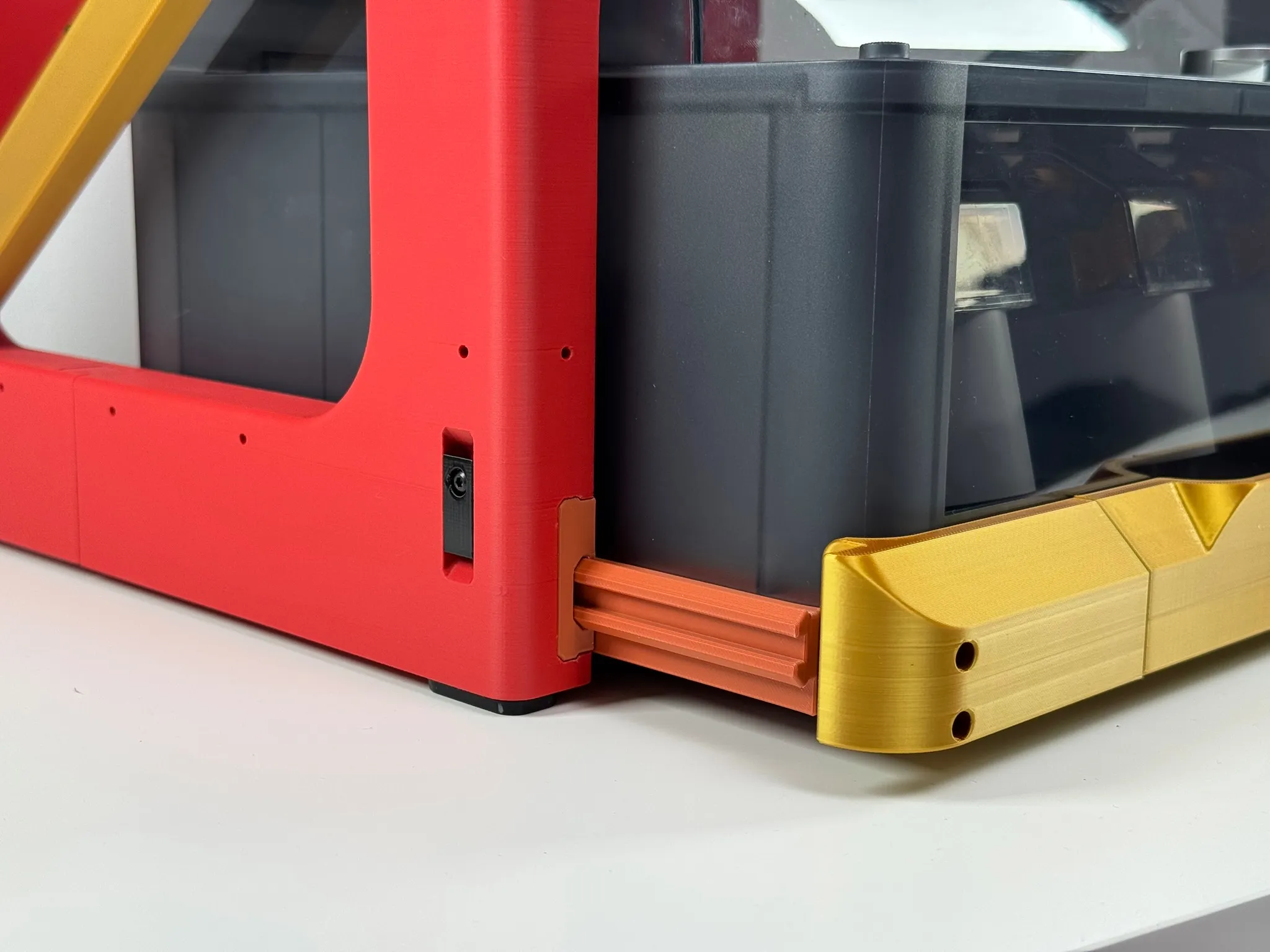
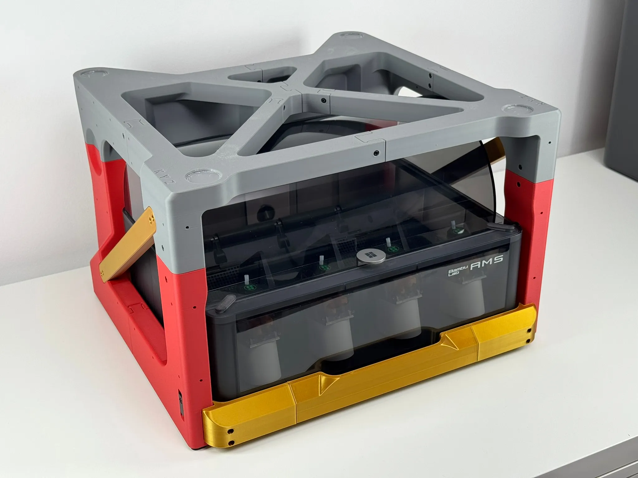
Lubricate the rails. Use whatever plastic-safe lubricant you have on-hand.
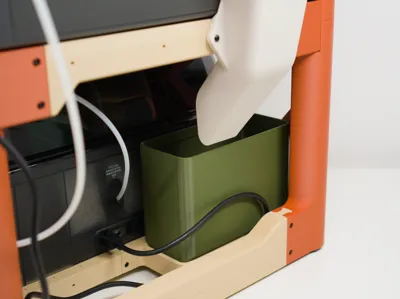
Prepare the poop chute
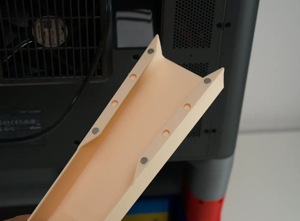
Glue in 4 D6x3mm magnets. You can use more if you wish. You can also use smaller magnets if you make adapters for them.
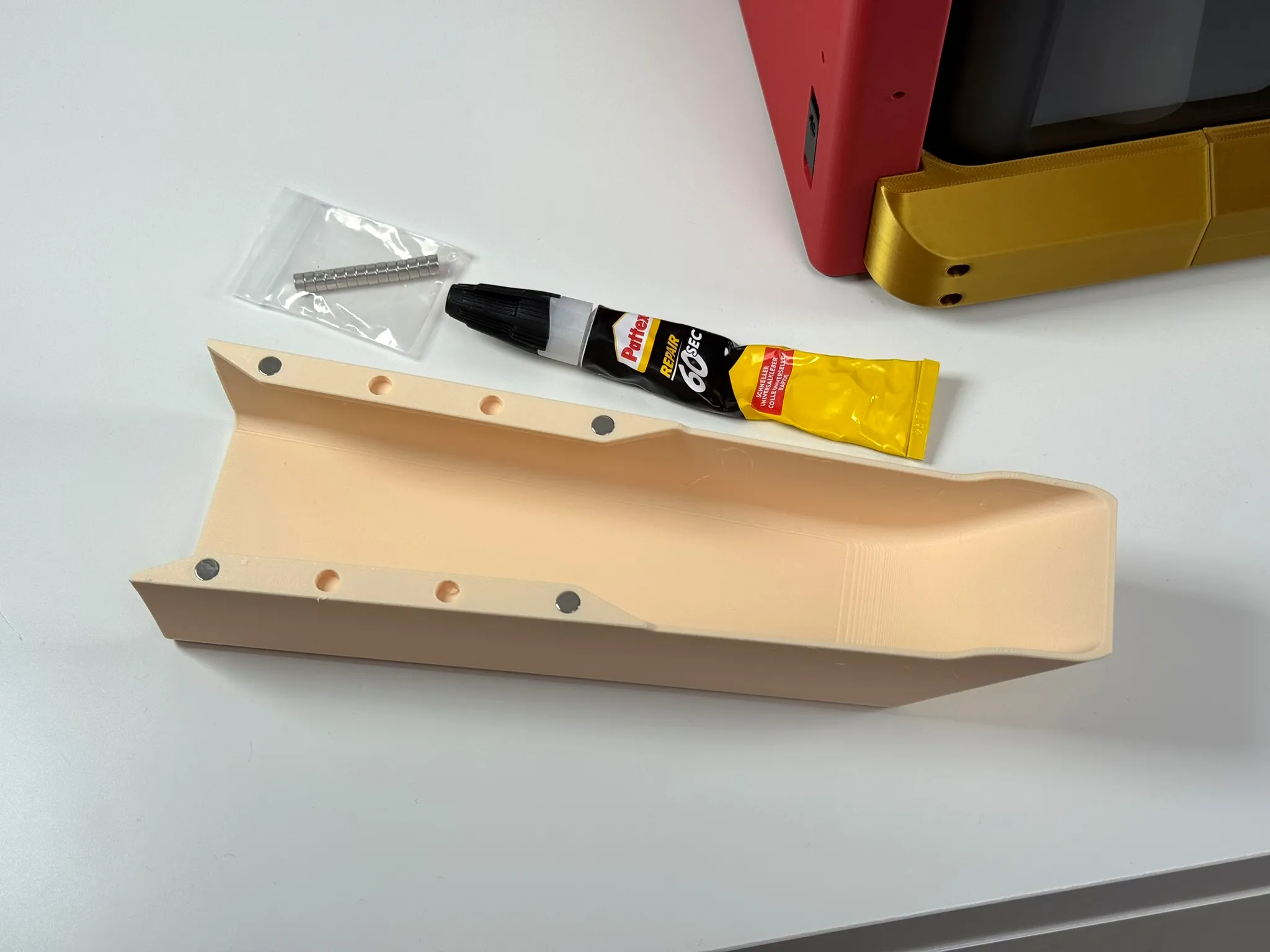
Install
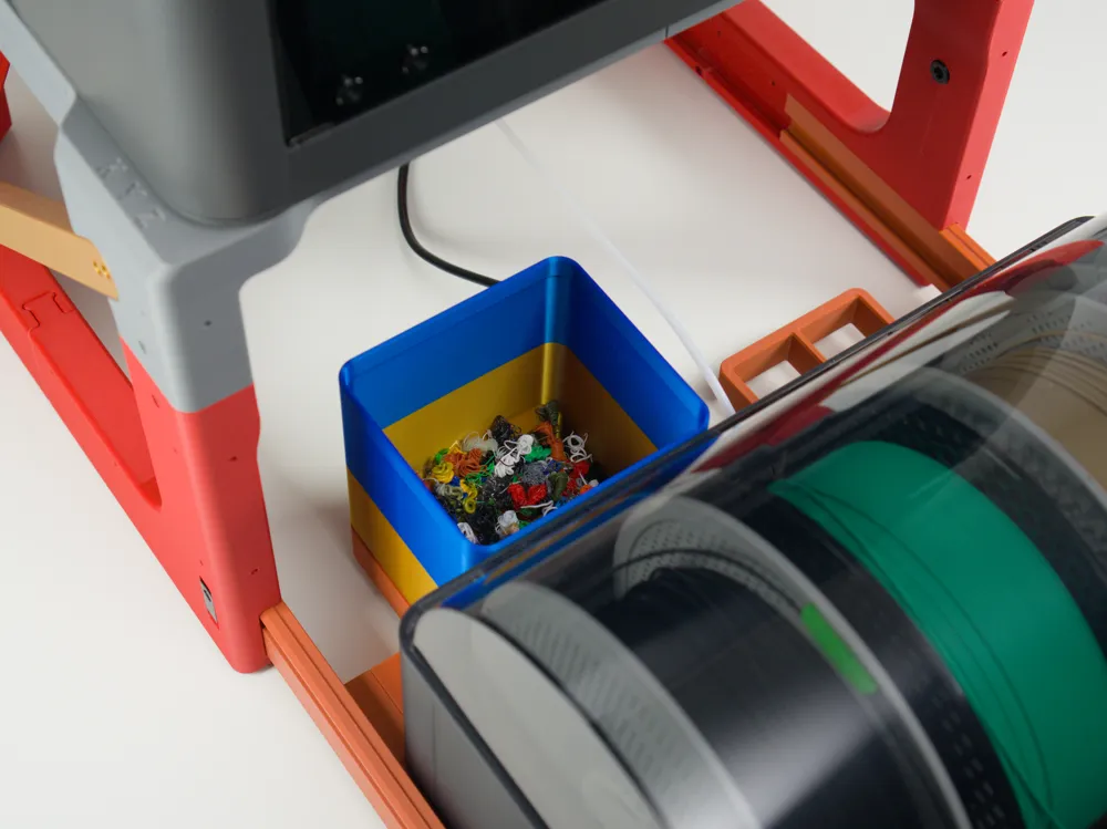
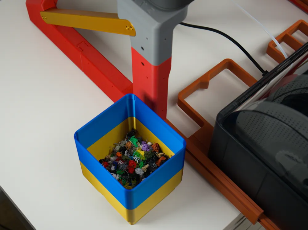
Put your printer on top, install the poop bin, align the poop chute, connect all the cables and tubes, check that the cable and tube lengths are sufficient for the slide movement.
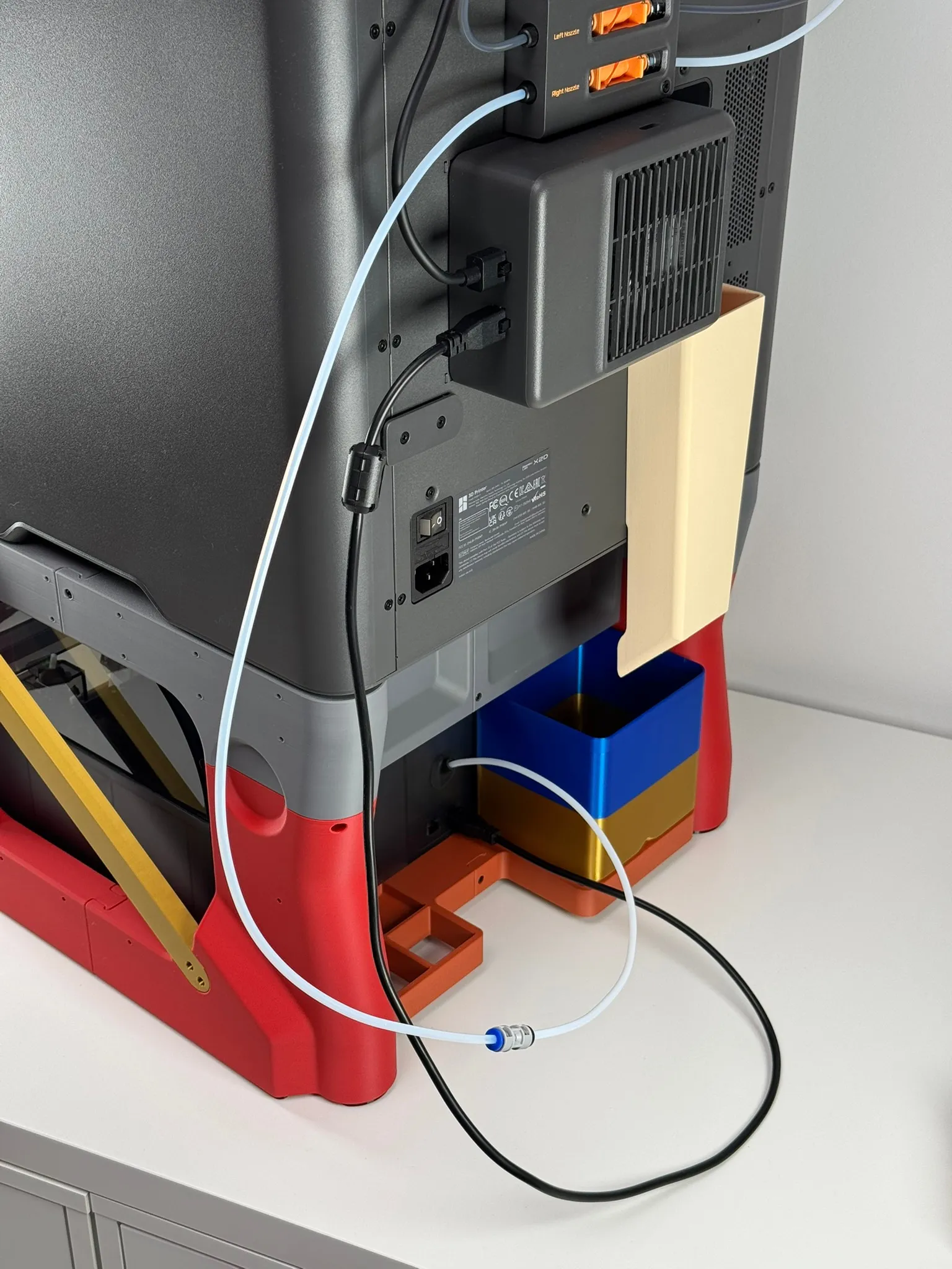
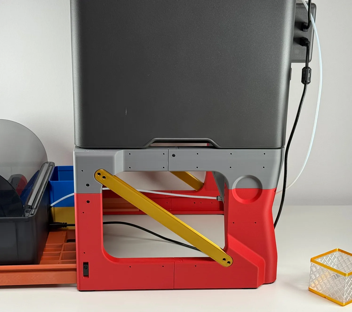
And finally, post a picture here! I want to make a gallery of cool colour schemes like I did with the Pasta Lite.
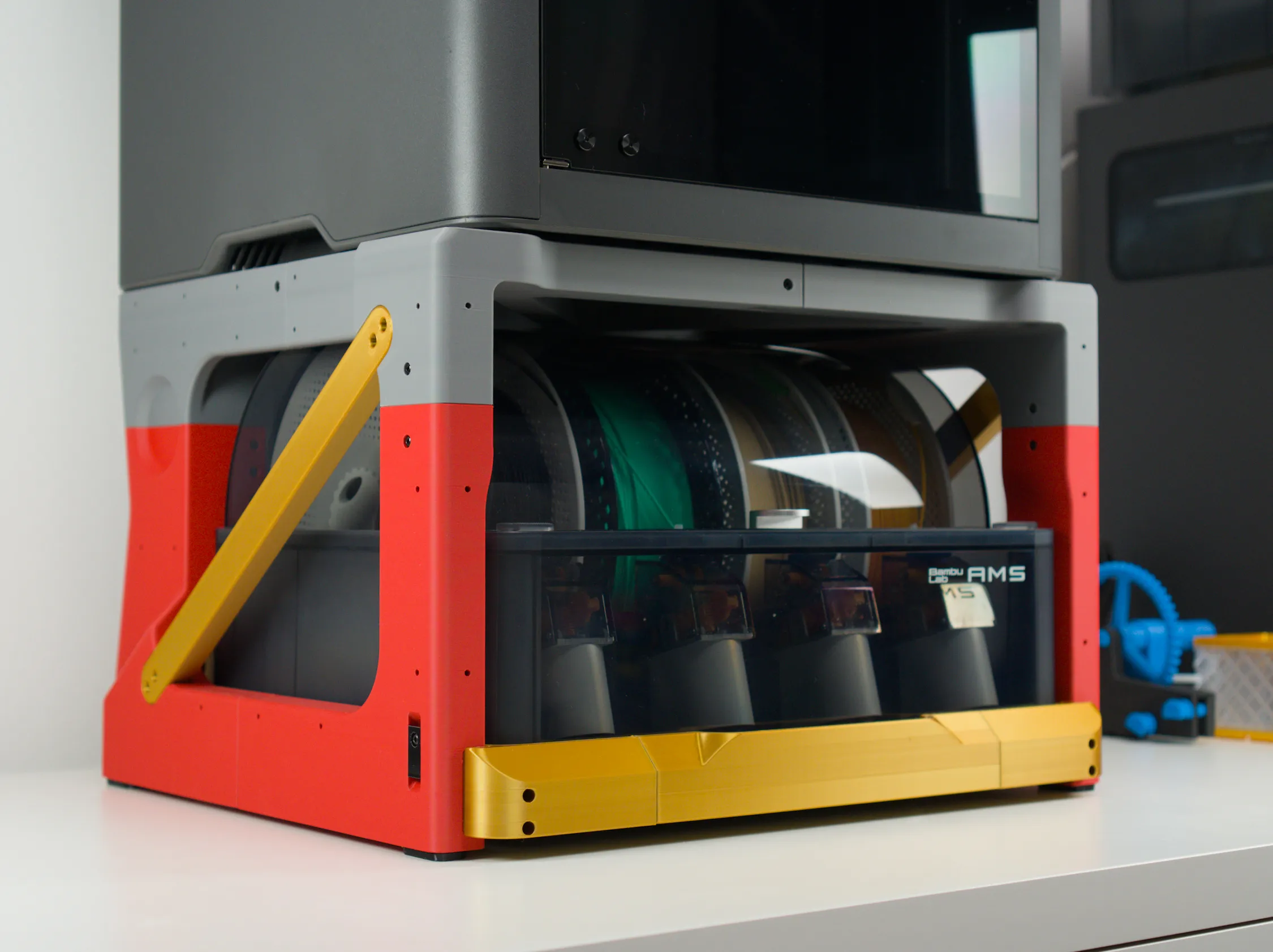
Support
If you make one, please share a pic on social media! Facebook, Reddit, Twitter, whatever! It really helps me out. And of course:
Boost Me (for free)
I've not used AI in any part of this project (not in design, not in photo editing, not in writing this page), I raw-dogged the whole thing! I hope this deserves your boost :)
Changelog
01/05/2026
Original release
06/05/2026
v2.0 released with
- New, stiffer frame
- Frame rear lower crossbar removed to allow easier cable and tube movement
- Frame front upper edge set back from the front face to make it easier to scoop rubbish out of the printer chamber into a bin
- Reworked slider rear crossbar with a 2x2 gridfinity grid added
- New poop chute that moves with the printer and larger poop bin
- Slide outer rails has minor changes but v1.0 ones will still fit
- Slide inner rails and handle unchanged
07/05/2026
Steel slide conversion kit released
21/05/2026
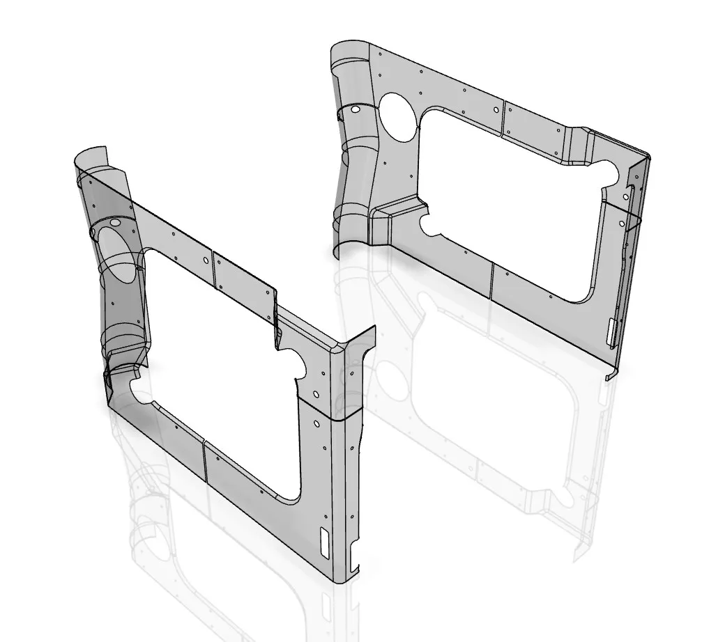
Hardpoint map uploaded: STEP file with external surfaces uploaded (pictured below). This can be used to locate the external screw holes and for designing attachments. Feel free to design your own attachments for the Undermount and upload them as original creations.
23/05/2026
Print Settings section of this page updated with notes on shrinkage and specific print settings
26/05/2026
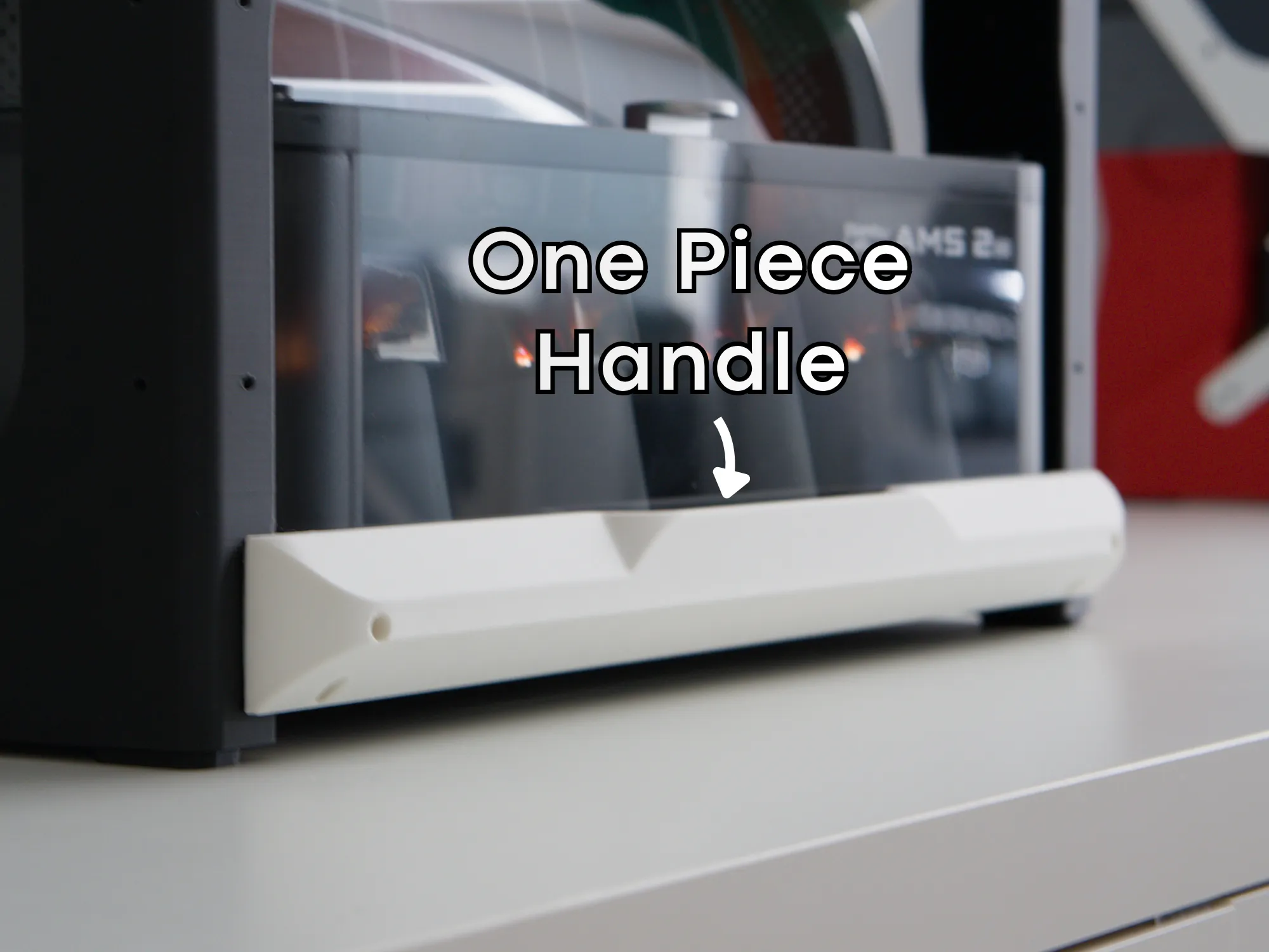
Print profile added for a 1-piece handle, printable on the H series printers and other large printers. This has a slightly different geometry and is compatible with the steel slide conversion kit. This will require 4 less screws to assemble as 2 joints are eliminated.
27/05/2026
Upper frame update:
- Front frame connector biscuit connectors integrated into upper front frame pieces (4 less screws and 2 less parts needed)
- Geometry update to reduce the large “layer time” changes for a better surface finish on high-shrinkage parts such as ABS/ASA.
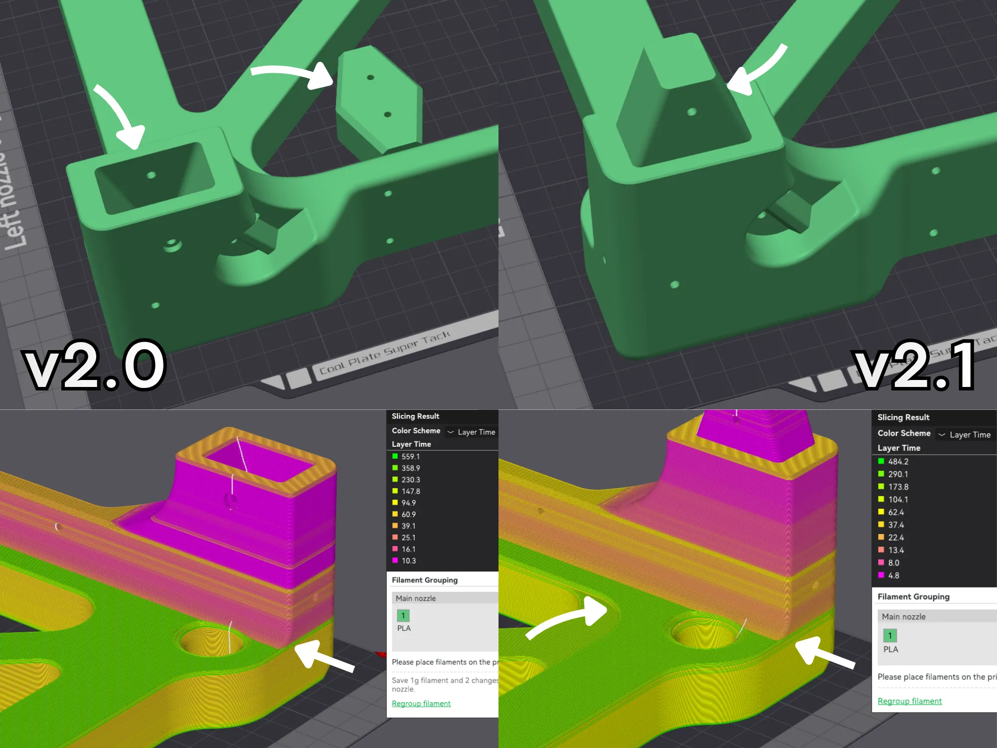
All 4 upper frame parts are affected. No other parts are changed and the v2.1 upper frame parts still fit with v2.0 lower frame. If you started printing v2.0 upper frame parts, you should continue printing the rest of v2.0 upper frame parts, you cannot mix-and-match v2.0 upper frame parts with v2.1 upper frame parts.
28/05/2026
STEP file of poop chute uploaded. Feel free to remix this and either upload it as a print profile on this page for minor changes (such as a change in magnet size or length) OR as an original design for major changes (such as enclosing it).
License

You shall not share, sub-license, sell, rent, host, transfer, or distribute in any way the digital or 3D printed versions of this object, nor any other derivative work of this object in its digital or physical format (including - but not limited to - remixes of this object, and hosting on other digital platforms). The objects may not be used without permission in any way whatsoever in which you charge money, or collect fees.


Comment & Rating (178)