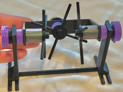
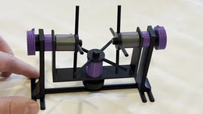
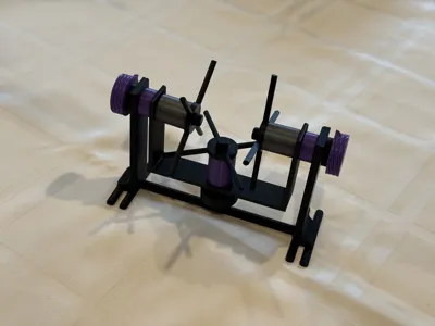
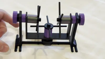
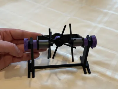
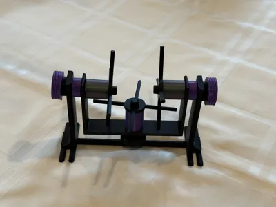
Mechanical Differential Demonstrator-100% Printed!


Print Profile(3)

Description
This mechanical differential demonstrator is entirely 3D printed (no other parts needed), and is based on the model used in this fantastic video from 1937 which describes exactly how a mechanical differential works: https://en.wikipedia.org/wiki/File:Around_the_Corner_(1937)_24fps_selection.webm
Assembly instructions are provided below--please scroll down to read everything!
Mechanical differentials have a variety of uses, but the most common application is for the power train in automobiles, and this system allows for automobiles to turn corners while wheels on both sides of the car are powered. When cornering, the wheels must rotate at different speeds--however, there is only one drive shaft coming from the engine. For an excellent description of mechanical differentials and their applications, please check out the Wikipedia article: https://en.wikipedia.org/wiki/Differential_(mechanical_device)
ASSEMBLY INSTRUCTIONS:
Please let us know if you have any questions or face any difficulty with the assembly! If any of the small snap clips break and you need to replace them, there is a separate print profile which allows you to print spares of just the snap clip. The full assembly instructions are as follows:
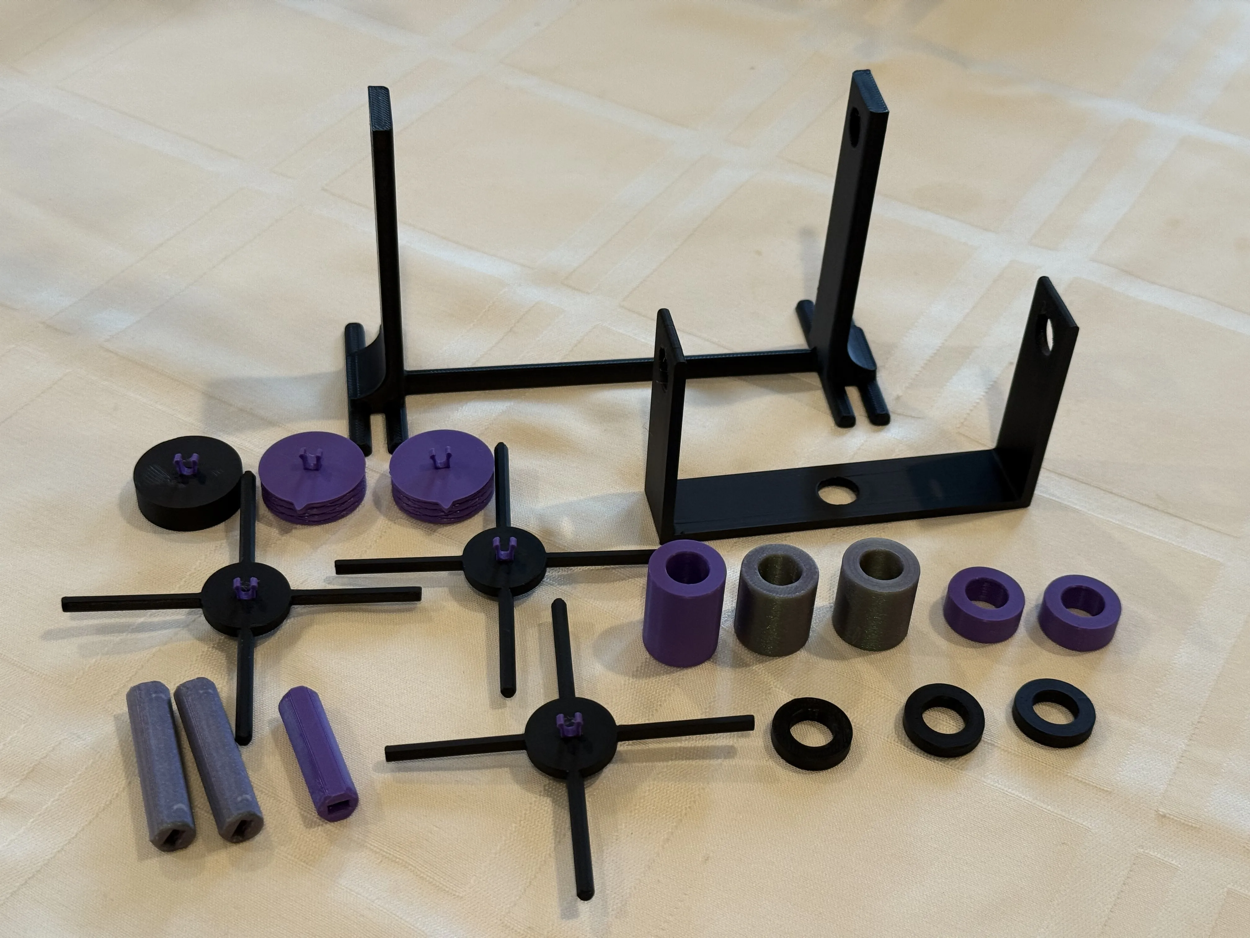
Lay out the printed parts, organizing the various pieces by size:

Take the size snap clips, and insert them into the three spoke wheels, the two knurled knobs, and the one plain knob as shown:
Take the plain knob, and snap the 31mm rod onto it (this is the shortest rod piece, there is only one of them). Then, place one of the 4mm spacers on it like so (the 4mm spacer is the shortest spacer, there are three of them in total):

Place the knob/rod/spacer assembly into the middle hole of the bracket mount like so:
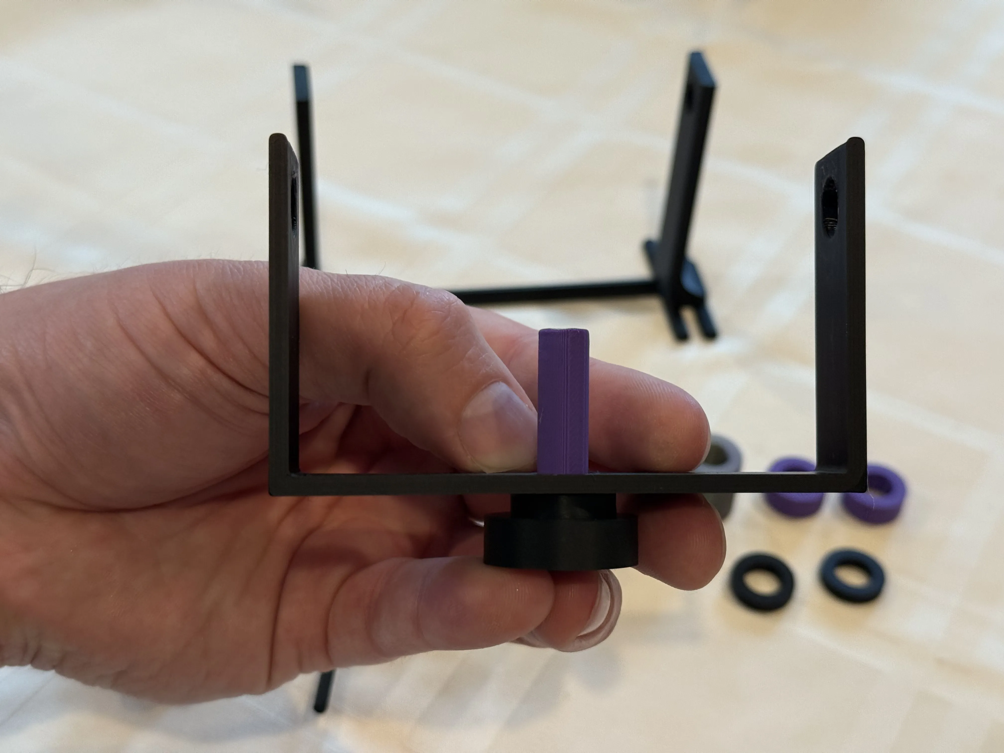
Slide the 24mm spacer ring (the largest of them, there is only one) onto the rod, then snap one of the spoke wheels onto the top of the rod to hold everything in place:

Take one of the knurled knobs and snap one of the 40mm rods (there are two of these) onto the knob. Then place another one of the 4mm spacer rings (again, these are the smallest/shortest spacers) onto the rod:

Slide the knurled knob and rod assembly into one of the holes in the stand, then place one of the 8mm spacer rings (there two of them, these twice as tall as the smallest 4mm spacers) over the rod as shown:

Slide the bracket mount onto the rod that was just inserted into the base as shown:

Now slide one of the 20mm spacer rings (two of them printed, these are the second largest spacers printed, and should be the largest of the remaining parts) onto the exposed rod, and then snap one of the spoke wheels onto the end to hold the assembly in place:

Repeat steps 6-9 for the other side of the stand/bracket mount as shown:


Done! Enjoy your new mechanical differential demonstrator!

PRINTED PARTS LIST:
- 3x Spoke Wheels
- 1x Base/Stand
- 2x Knurled Knobs
- 1x Plain Knob
- 1x Bracket Mount
- 1x 31mm Rod
- 2x 40mm Rod
- 3x 4mm Spacers
- 2x 8mm Spacers
- 2x 20mm Spacers
- 1x 24mm Spacer
- 6x Snap Clips
License
You may create derivative works based on this object, provided that all such derivative works are published exclusively on the MakerWorld platform and include proper attribution to the original creator. You may not share, upload, host, distribute, or publish this object—or any derivative work of this object—on any other digital platform, marketplace, or distribution channel. Commercial use of this object and any derivative works is strictly prohibited. This includes, but is not limited to, selling, renting, sublicensing, or using the object in any context in which you receive monetary compensation or other financial benefits.
Comment & Rating (0)