DIN14 plug for ATARI ST & AMSTRAD PC


Print Profile(1)
Description
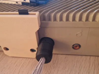
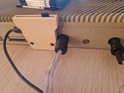
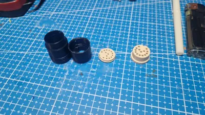
This is a complete replacement for DIN14 plug used in Atari ST, Atari PC and Amstrad PC1512 & PC1640 computers. Which is a quite expensive connector when you try to buy few for your computers, but with thşs you can make your own connectors for less than 5 euros each. Pin diameter should be 1,7 mm, you could extract pins from any standart DIN connector, such as 2 DIN7 connectors. Screw is 1.2x5 or 2x5. If you're gonna print multiple of this connector you just need to print the “pin alignment tool” just once, we are using it to hold and align pins while making the connector.
0.2mm NOZZLE IS A MUST, OTHERWISE IT WON'T WORK!!!
PRINT “BASE” AND “ALIGNMENT TOOL” WITH ABS OR ASA , OTHERWISE THEY WILL MELT WHILE SOLDERING. You can print the “case” in any material except PLA becaue PLA may break down during use.
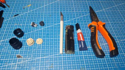
Things you will need:
- 3d printed parts
- Some DIN connectors to extract pins from
- small knife
- lighter
- super glue
- needle nose pliers
Assembly:
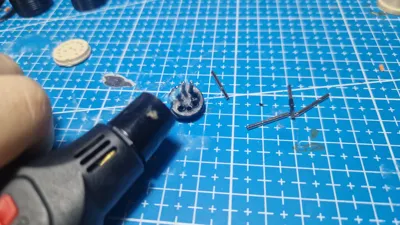
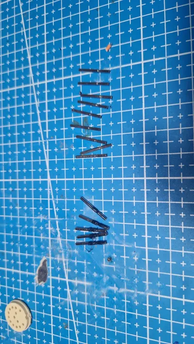
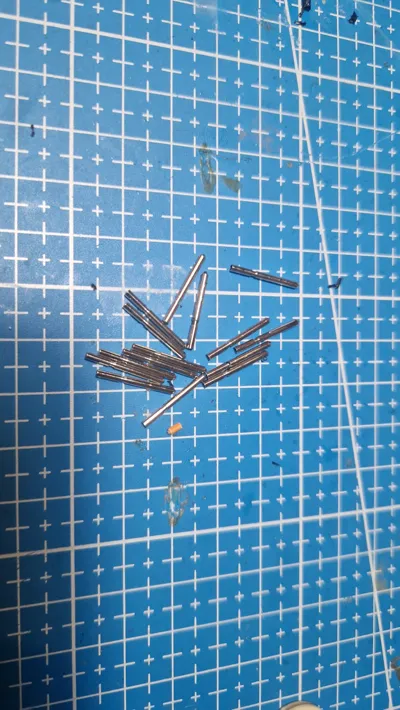
1: Extract the pins from the DIN connectors: heat the pins using lighter and pull them out with needle nose pliers. If you use just enough heat pins will come out with any residue on them, if you use too much heat there will be burnt plactic residue on the pins, if you use too little heat you won't be able to pull them out.
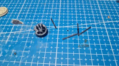
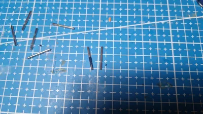
2:Prepare the pins: once you pull all 14 pins from the DIN connectors seperat them into 2 groups, ones with burnt plastic residue on them and ones without any residue. Put the conectors without a residue on the side, and scrape off all the burnt plactic from each pin using the small knife.
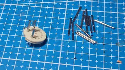
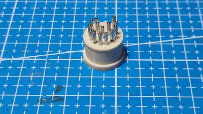
3: Insert the pins into the “base”: insert them from the side thats facing the build plate. (you don't have to care about how much they went into the base in this step)
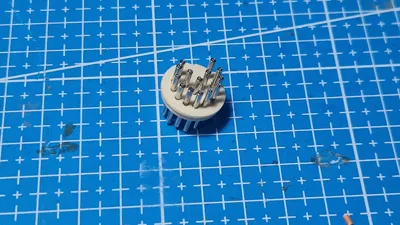
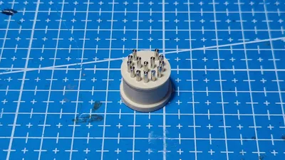
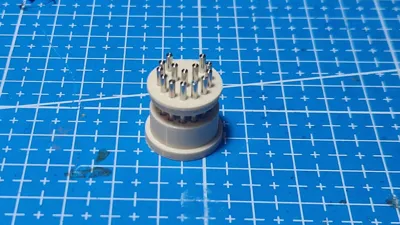
4: Preparing to seat the pins: when you inserted all 14 pins to the “base” place tha base on top of the “alignment tool”, like in the picture, make sure “base” and “alignment tool” is flush to each other and alignment tool is on a flat surface.
5: Fully seatşng the pins: press each pin down with the pliers until they hit the ground, “alignment tool” ensures pins are parallel to each other and correct amout of them are sticking out from the front.
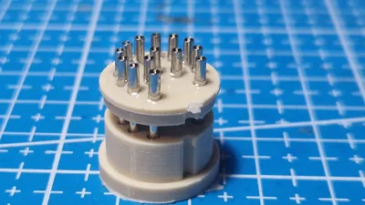
6: Gluing the connector: pull the connector slightly out of the “alignment” tool and pour A LOT of super glue on the top side of the connector
7: Soldering: once everything is dried up(wait at least 30 minutes) you can solder wires to it and put the connector together, you should keep the base in the alignment tool during the soldering, otherwise base may deform under the heat and connector may become unsuable.
Note:
don't forget to pass the cables from the hole on the case before starting to solder.
keep the connector in the “pin alignment tool” during the soldering.
Connections:
I am including a link for the atari floppy connector and an image for the regular 3,5" floppy connector.
note that Atari's floppy connector is viewed from the solder side, and the regular floppy connector is viewed like you're looking at the back of a PC floppy drive. (to be very clear put the floppy drrive on a flat surface, spindle motor should be facing down, to the surface, and label of the floppy drive should be looking to the sky. the face of the floppy drive,place you insert the floppies, should be looking away from you)
you are not connecting pin 2 and pin 34 from the regular floppy connector. unmarked pins in the regular floppy connector are ground, use both of the ground pins on the atari's floppy connector and connect them to the any of the 2 ground pin on the regular pc connector.
some of the signals in Atari's floppy connector have same names as signals in the regular floppy connector, you can directly connect them to the regular pc floppy connector.
Rest of the connections goes like that.
ATARI connector → regular connector
Side 0 Select → Head Select
Drive X Select → Motor Enable A
Drive Y Select → Drive Select B
Motor On → Motor Enable A
Write Gate → Write Enable
DO NOT CONNECT “DRIVE SELECT A” ON THE REGULAR FLOPPY CONNECTOR, TO ANYTHING.
https://info-coach.fr/atari/hardware/interfaces.php

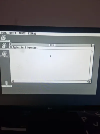
This is a tested and working cable on my Atari 1040 STfm and an ALPS DF354H floppy drive.
MODS LISTED BELOW ARE NOT REQUIRED WHILE USING THIS CABLE.
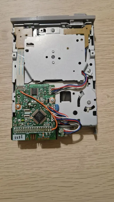
you can also modify an alps DF354h to work as a internal disk drive on your atari ST
This is the link if you want to modify your own DF354H: https://www.exxosforum.co.uk/forum/viewtopic.php?t=415
If you exactly follow the guide it won't work, don't ask me how I know.
The cap across the power rail is optional.
You only need to connect the “HD select” wire if you are using some kind of high density disk mod like the “LaST upgrade”, otherwise ignore this step
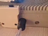
For atari you wil need to connect the pin 2 of the floppy drive to the GND, conveniently in the alps df354 there is a ground pad right next to the pin 2, you can use a small piece of wire to connect this pin to the GND pad. (You can see this on the last picture)
Also you we will need to media insertion(MS) signal on pin 1 of the floppy. For that connect the 4th wire from the ribbon to the 1st pin on the floppy cable, conveniently pin 1 and 8 on the ribbon cable are marked on the pcb, if your drive doesn't have the numbers just count away from the metal outer side of the drive. ın this drive cenveniently ther is a pad next to the ribbon cable named MS, you can take the media insertion signal from this pad. (You can see this on the last picture)
Comment & Rating (0)