V-Dipole SMA Antenna Mount 120°


Print Profile(1)
Description
Overview
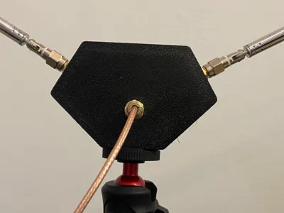
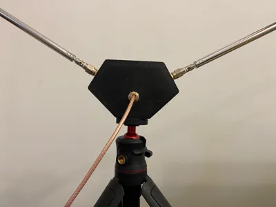
This is a compact, easy-to-print housing designed to create a 120-degree V-dipole antenna. The 120° angle is highly popular in the amateur radio and SDR (Software Defined Radio) communities, particularly for receiving NOAA and Meteor weather satellite images at 137 MHz, as well as general VHF/UHF scanning.
The design is sleek, functional, and utilizes standard SMA connectors to allow for quick swapping of telescopic antennas and coaxial cables.
Features
- Perfect 120° angle for optimal V-dipole performance.
- Designed to house standard SMA panel mount connectors.
- Compact, lightweight enclosure that protects internal solder joints.
- Two-part design (base and lid) for easy assembly and printing.
Required Hardware (BOM) To complete this build, you will need:
- 3x SMA Panel Mount Connectors (2 for the antenna arms, 1 for the coaxial output line).
- 2x Telescopic Antennas (with SMA connectors to attach to the arms).
- 2x M2.5 Self-Tapping Screws (to secure the lid to the base).
- 1x 10M Ohm Resistor (Highly recommended to bleed off electrostatic discharge and protect your SDR).
- 1x ¼ inch brass insert (for the tripod mount).
- A short length of wire (to solder the internal connections). 0.9mm Enameled Copper Wire suggested.
Printing Guidelines
- Material: PETG or ASA/ABS is highly recommended if you plan to use the antenna outdoors, as they offer better temperature and UV resistance than PLA.
Assembly Instructions
- Insert the three SMA panel mount connectors into their respective holes and secure them with their included nuts.
- Inside the box, solder a wire connecting the center pin of the bottom SMA (output) to the center pin of ONE of the side SMAs (this becomes your active element).
- Solder another wire connecting the ground (shield) of the bottom SMA to the center pin of the OTHER side SMA (this becomes your ground element).
- ESD Protection: Solder the 10M Ohm resistor across the two side SMA center pins (connecting the active element to the ground element). This will safely bleed off any static charge buildup from the wind without affecting the RF signal, protecting your sensitive SDR front-end.
- Place the lid on top and secure it using the two M2.5 self-tapping screws.
- Screw on your telescopic antennas, attach your coax cable to the bottom, mount it to a tripod, and you are ready to scan!
License
You may create derivative works based on this object, provided that all such derivative works are published exclusively on the MakerWorld platform and include proper attribution to the original creator. You may not share, upload, host, distribute, or publish this object—or any derivative work of this object—on any other digital platform, marketplace, or distribution channel. Commercial use of this object and any derivative works is strictly prohibited. This includes, but is not limited to, selling, renting, sublicensing, or using the object in any context in which you receive monetary compensation or other financial benefits.
Comment & Rating (0)