
Precision Picatinny Monopod - with static foot


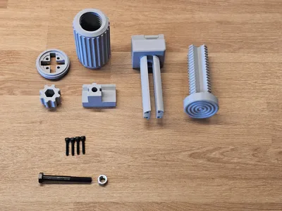
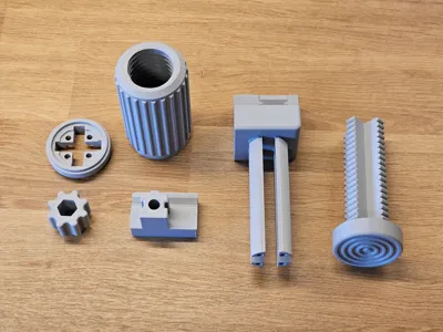
Print Profile(2)
Bill of Materials



Description
Hello everyone!
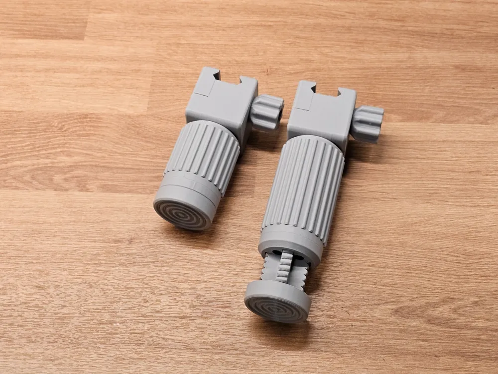
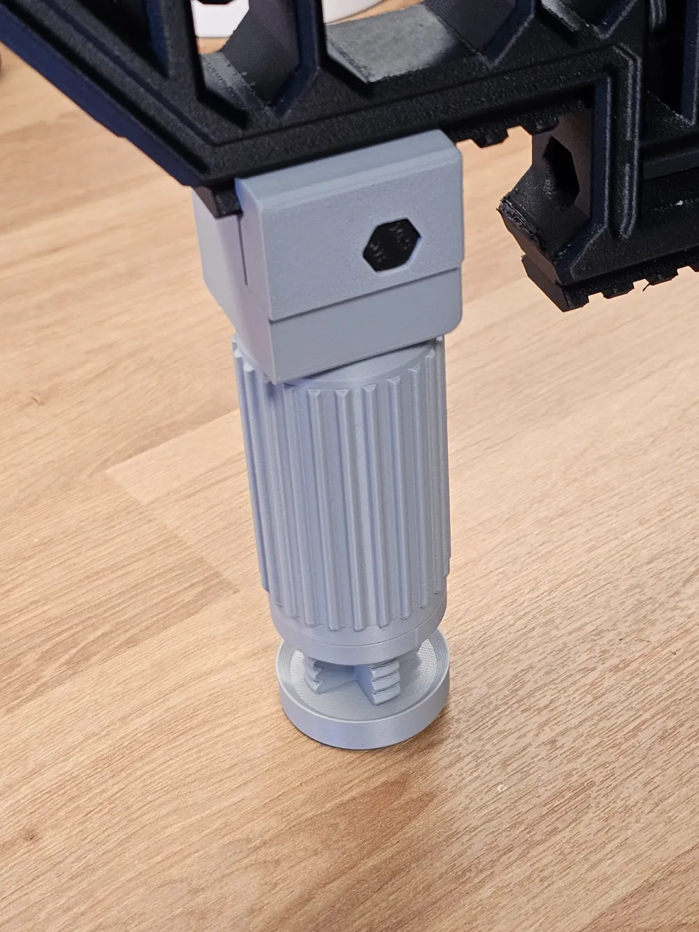
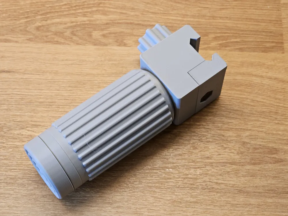
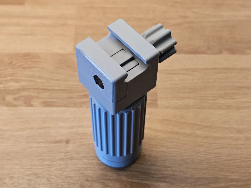
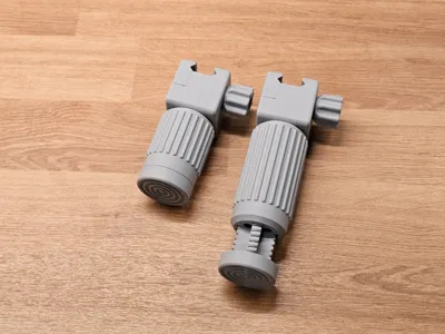
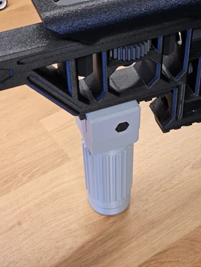
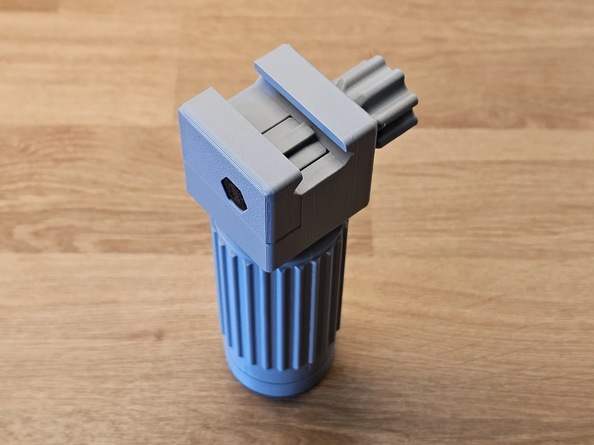
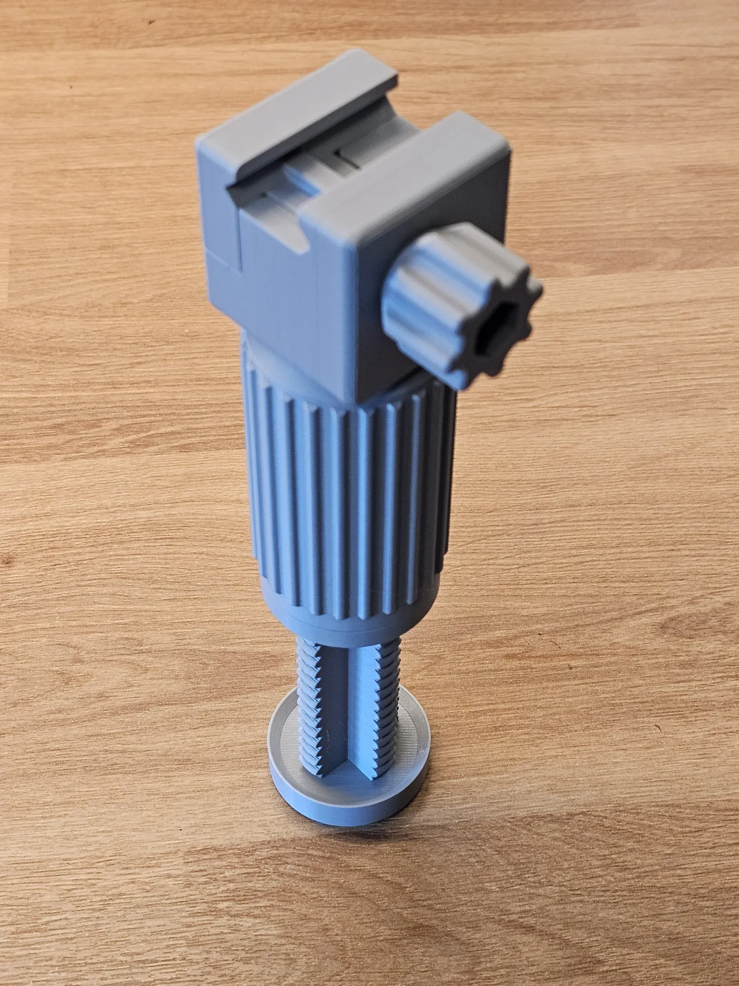
I’d like to introduce another version of my Picatinny-mounted precision monopod.
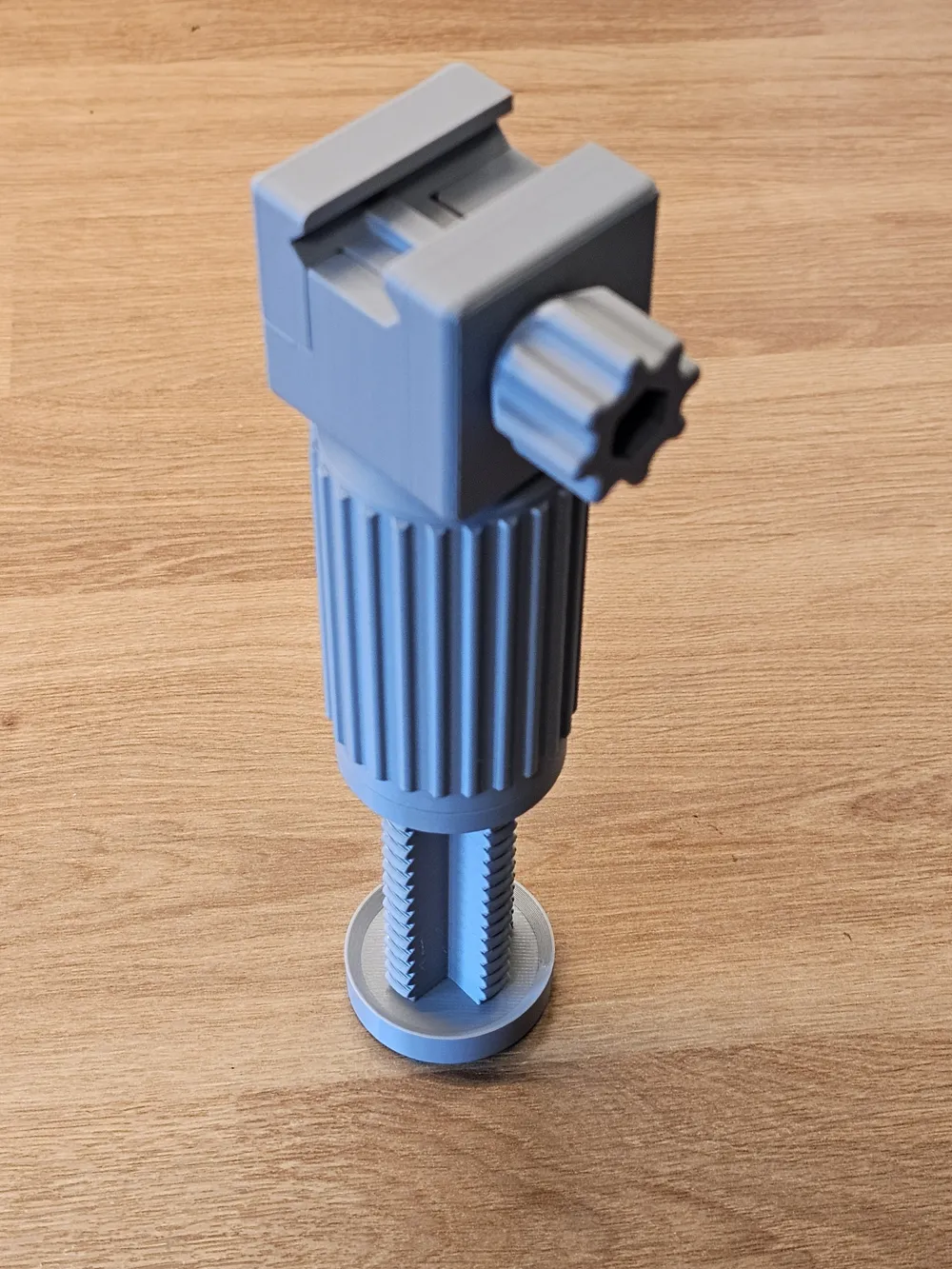
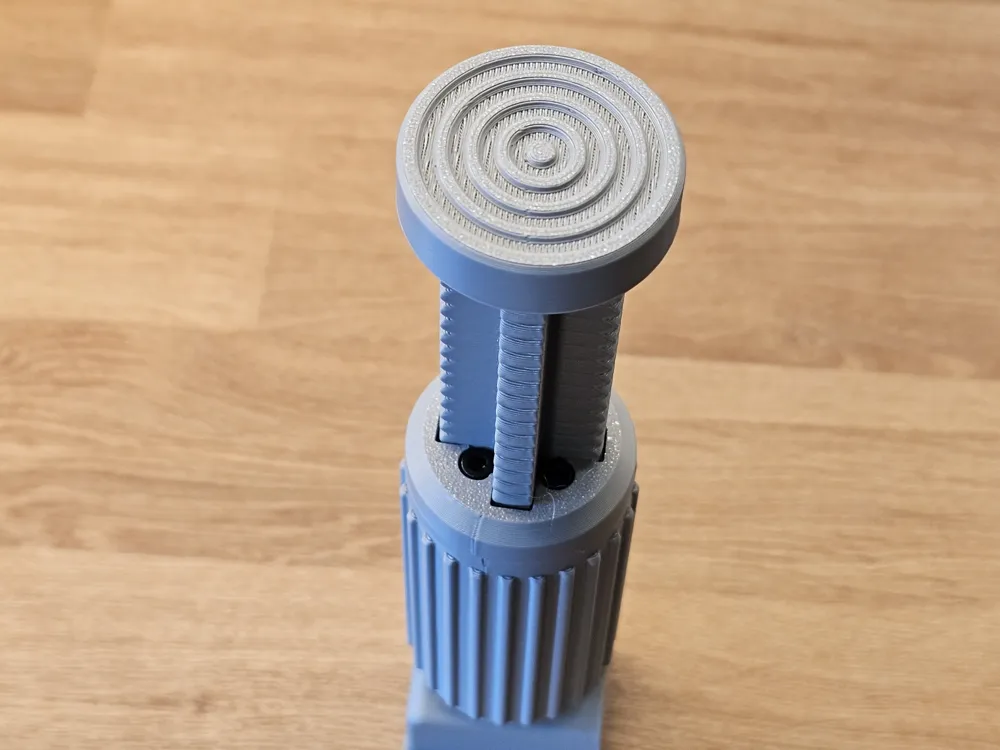
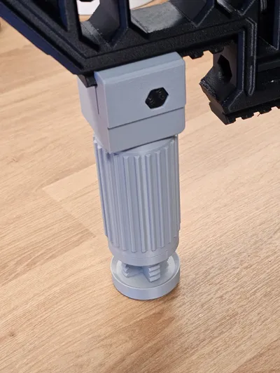
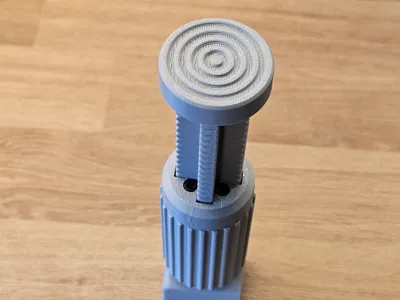
This version represents a different design approach compared to the original model. In the first version, adjusting the height causes the entire foot to rotate. In this new design, the foot remains completely static.
When adjusting the height, there is no lateral movement of the rifle — the foot simply extends vertically, providing consistent rear support.
Please note that this version is not as robust as the original model with the movable foot.
The first, stronger version is available here: link
Print with at least 50% infill
Beside normal support there is also a static support added to prevent warping of the main part during printing. After printing, simply break it off and clean the area with a scraper. It does not need to be perfectly smooth.
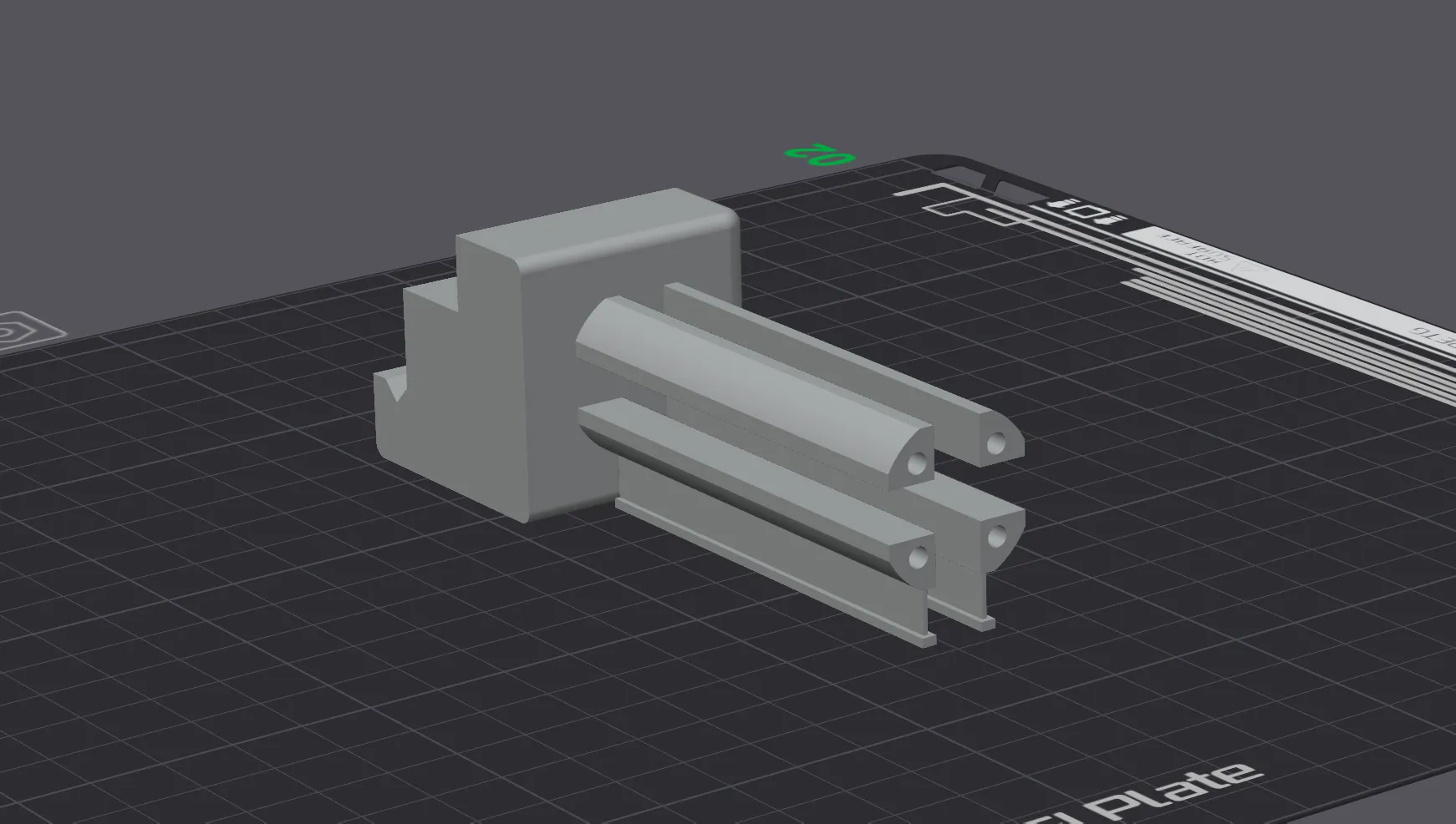
The monopod is available in two sizes:
Small – adjustment range from the Picatinny rail: 90–125 mm
Large – adjustment range from the Picatinny rail: 115–170 mm
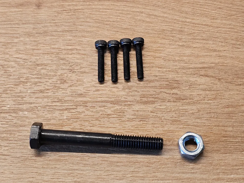
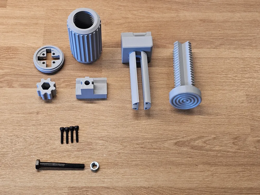
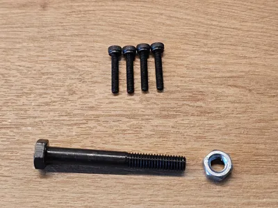
For assembly, you will need:
- 4 × M3×15–20 Allen head screws
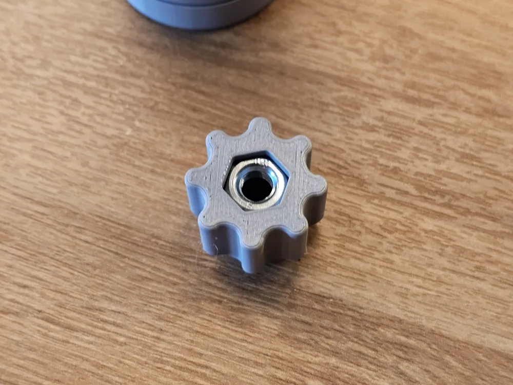
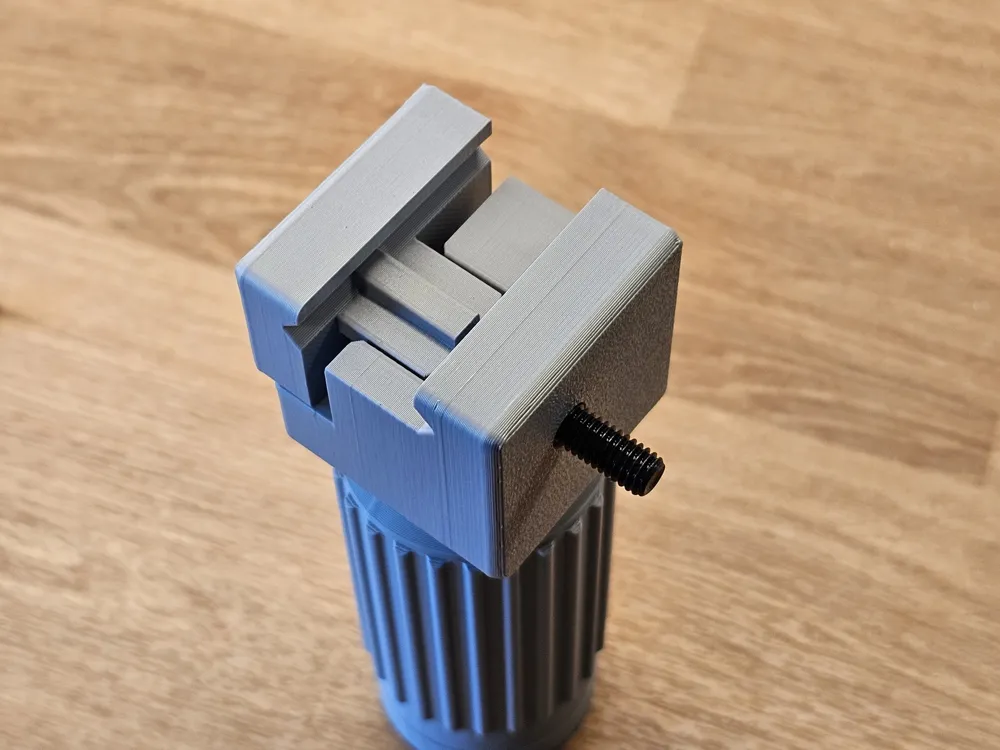
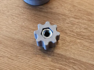
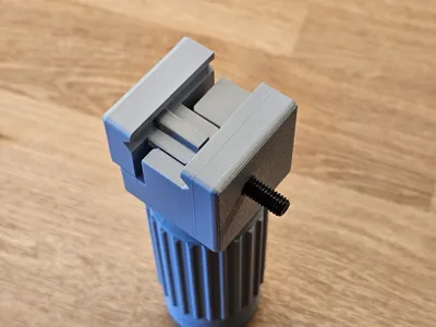
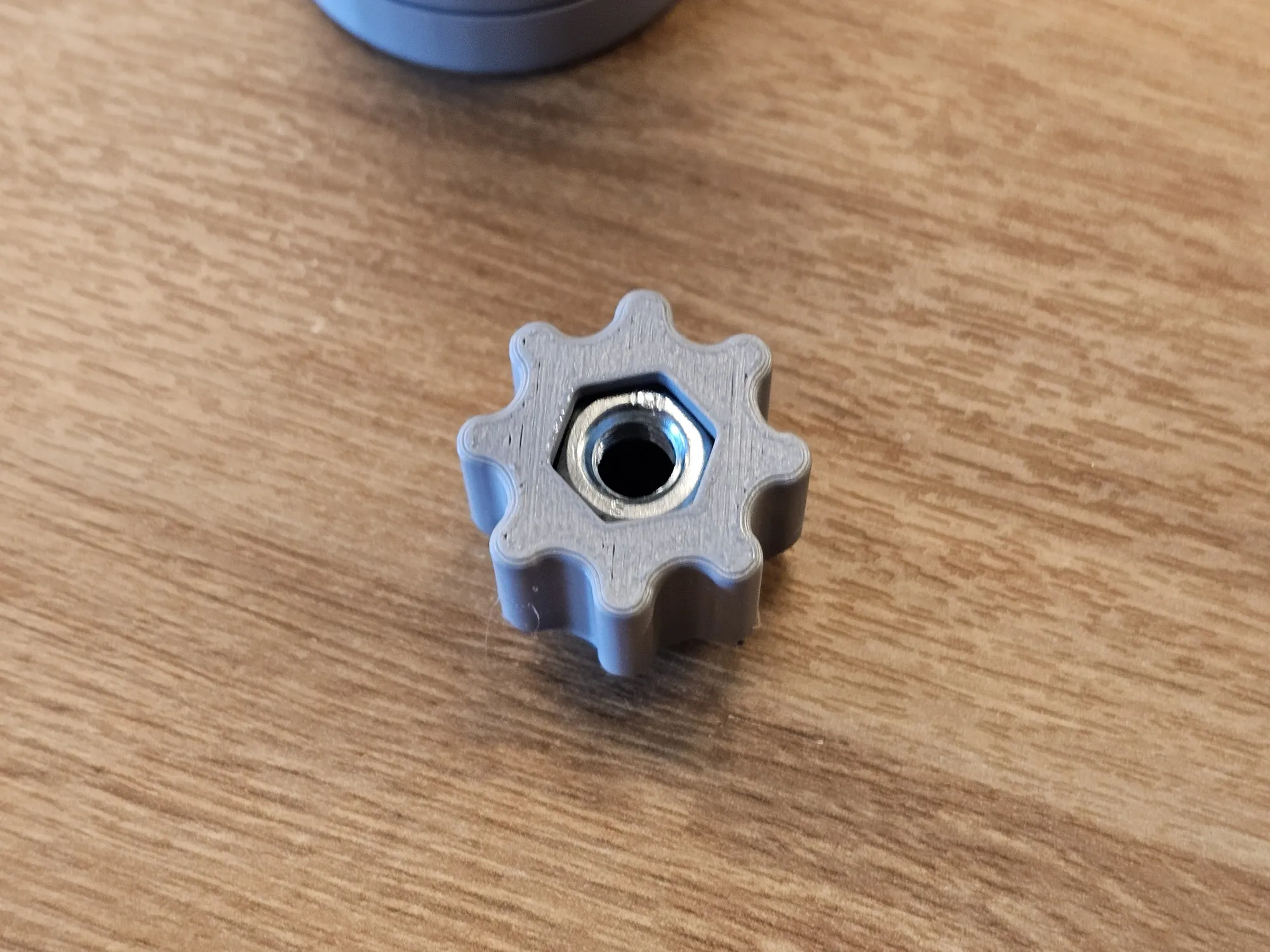
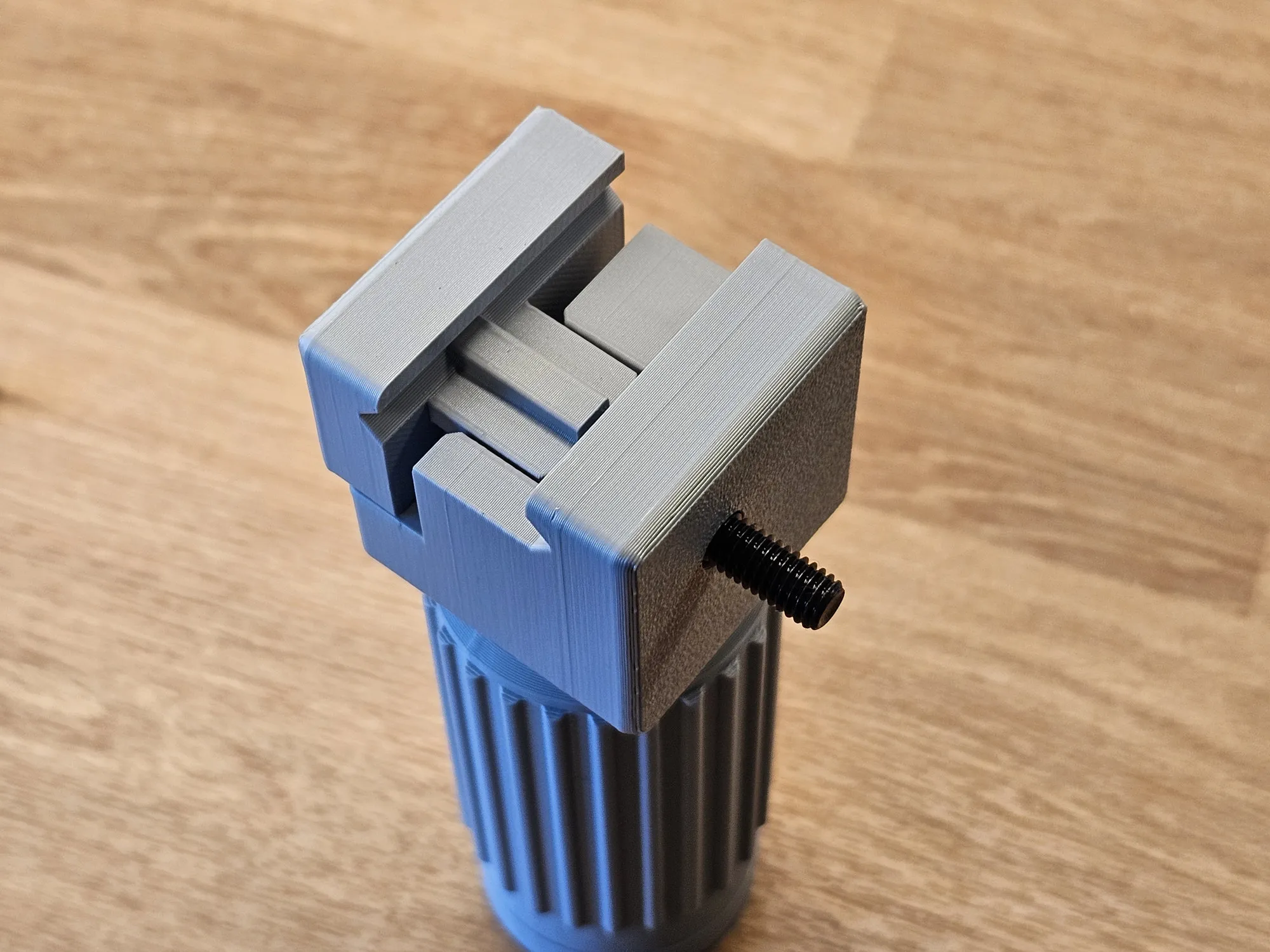
1 × M6×50 hex head screw with nut (for the Picatinny mount)
Assembly instruction:
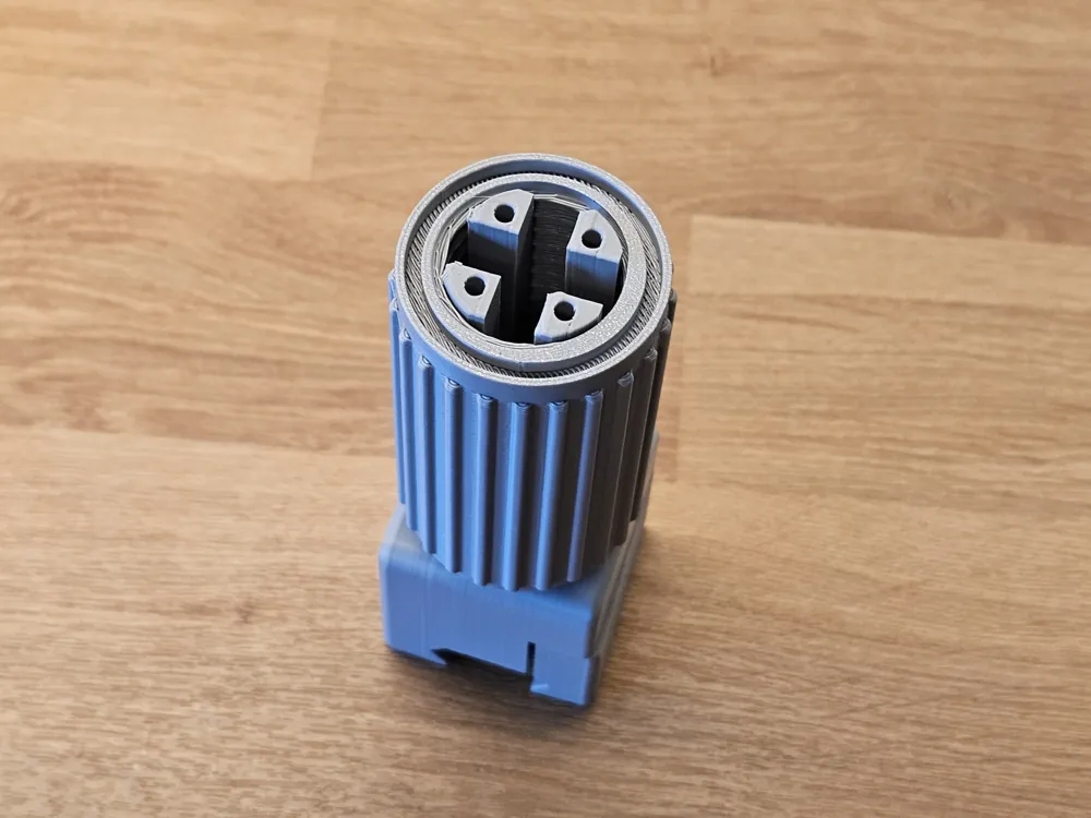
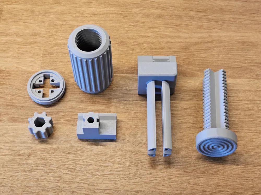
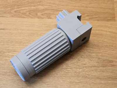
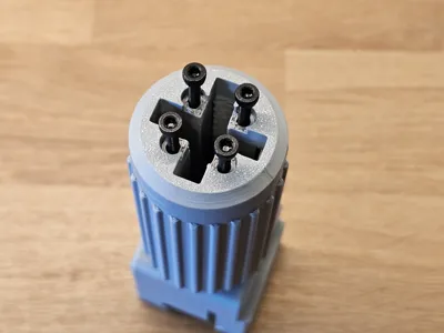
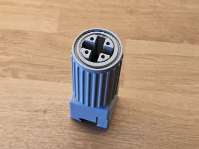
Prepare all parts 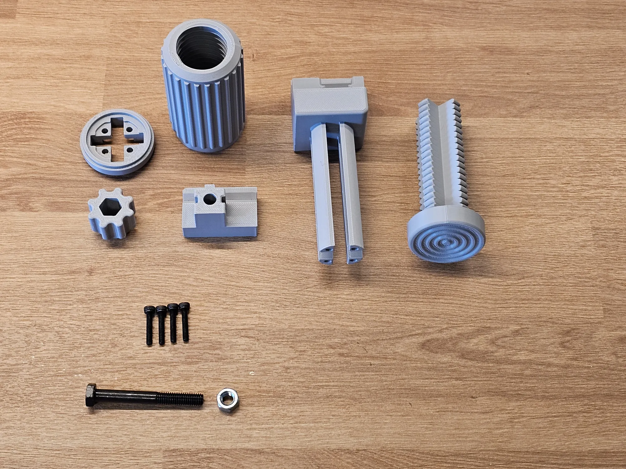 | Slide the rotating part onto the main body. 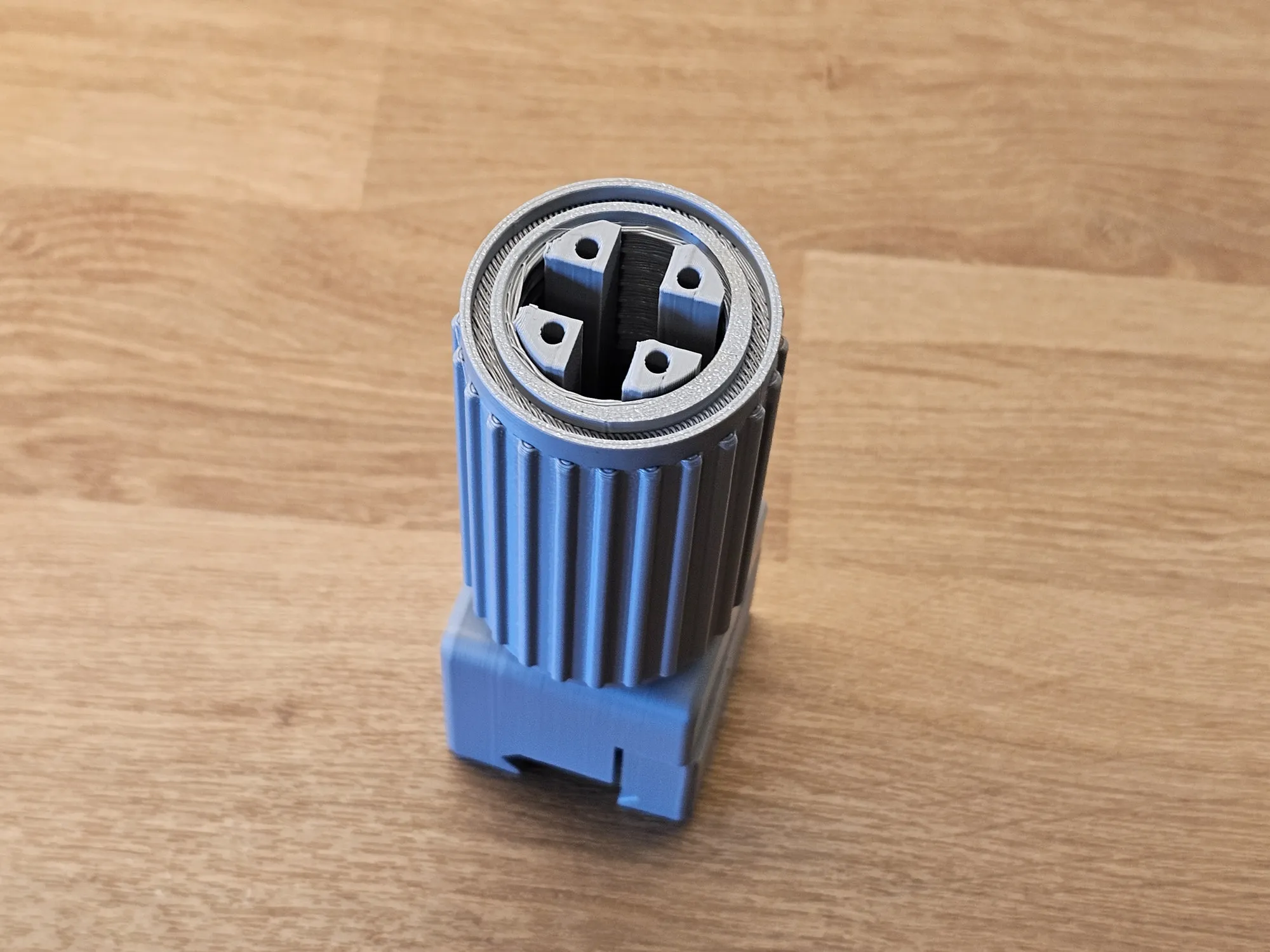
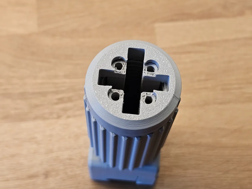
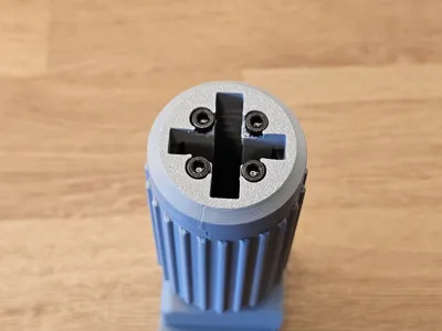
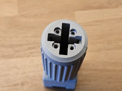
| Install the end cap with the screw holes. 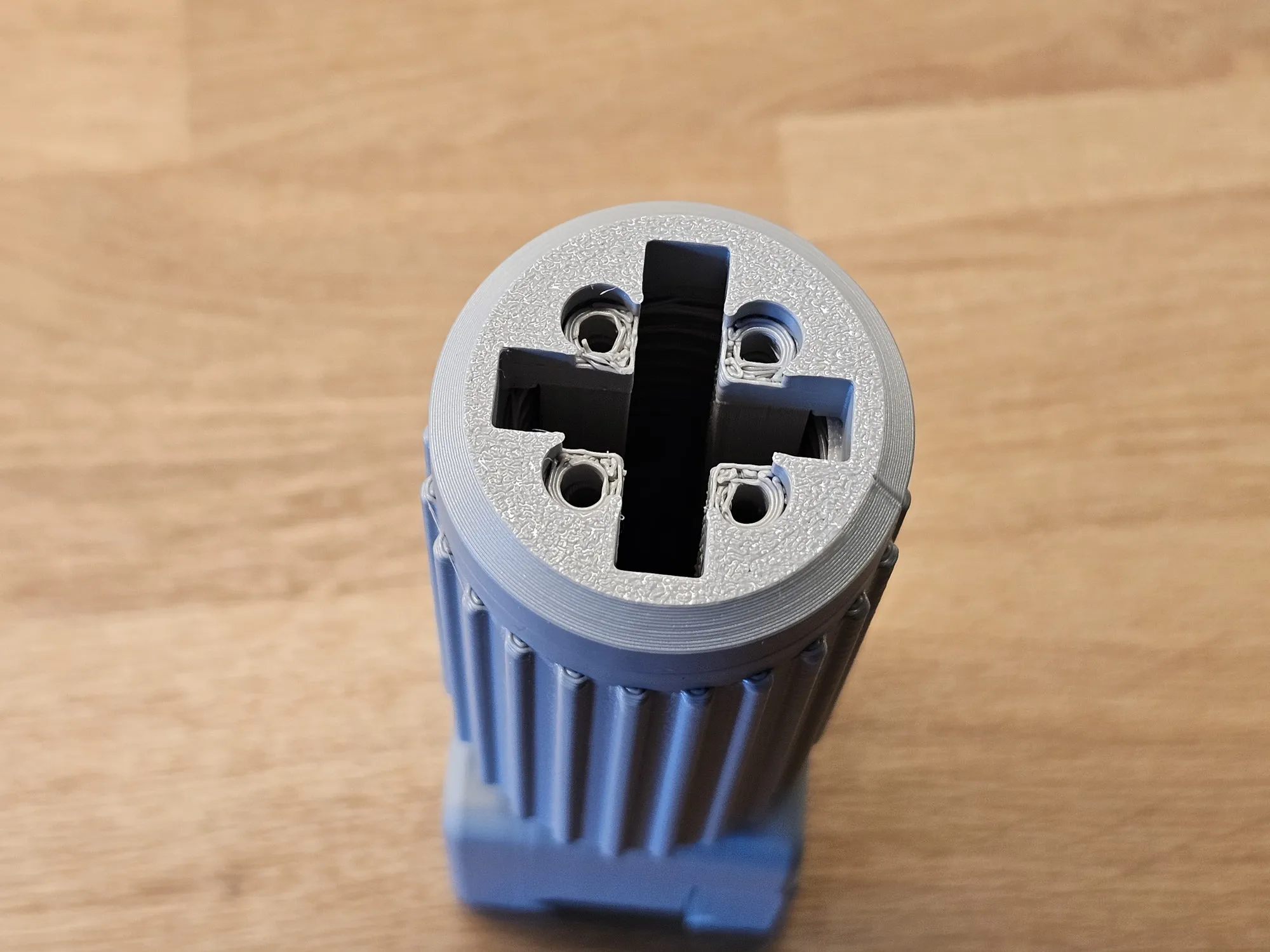
|
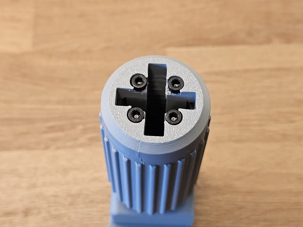
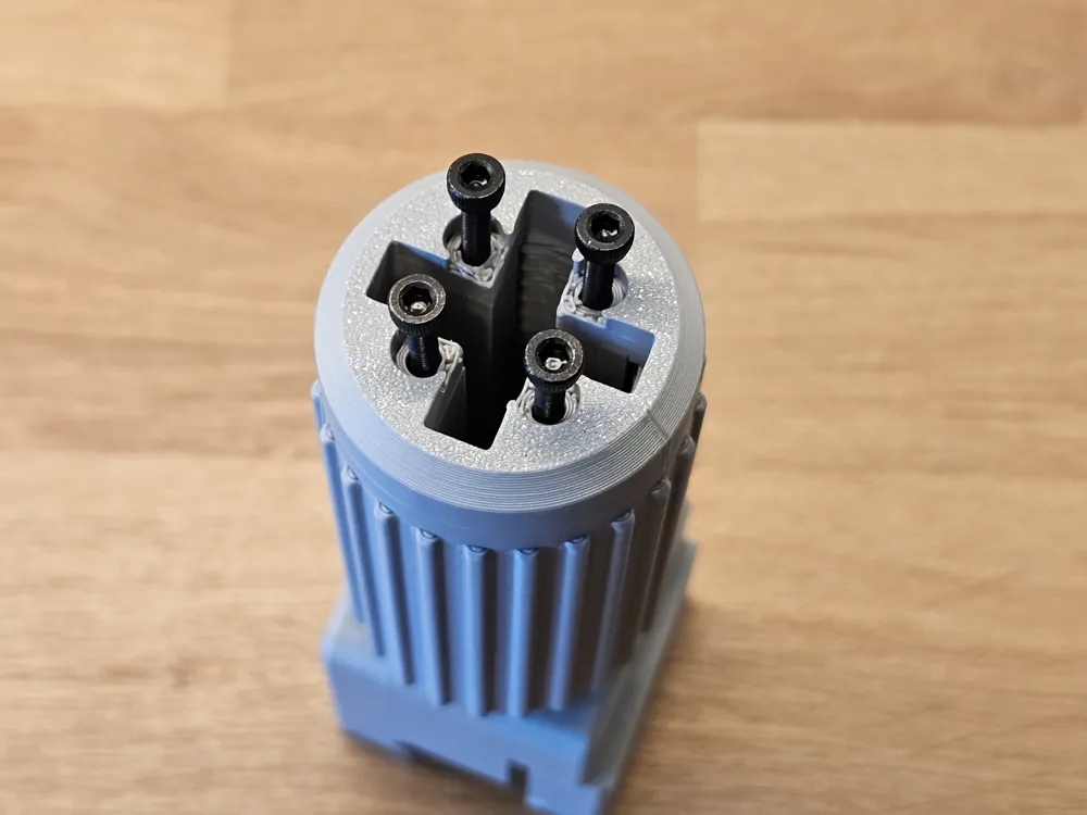
Secure it using 4 × M3×15 screws. 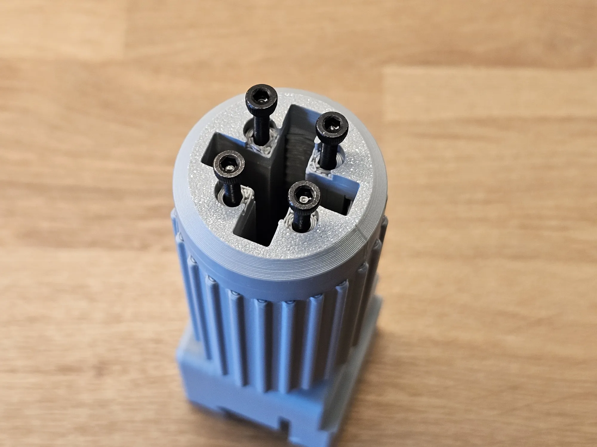 | Secure it using 4 × M3×15 screws. 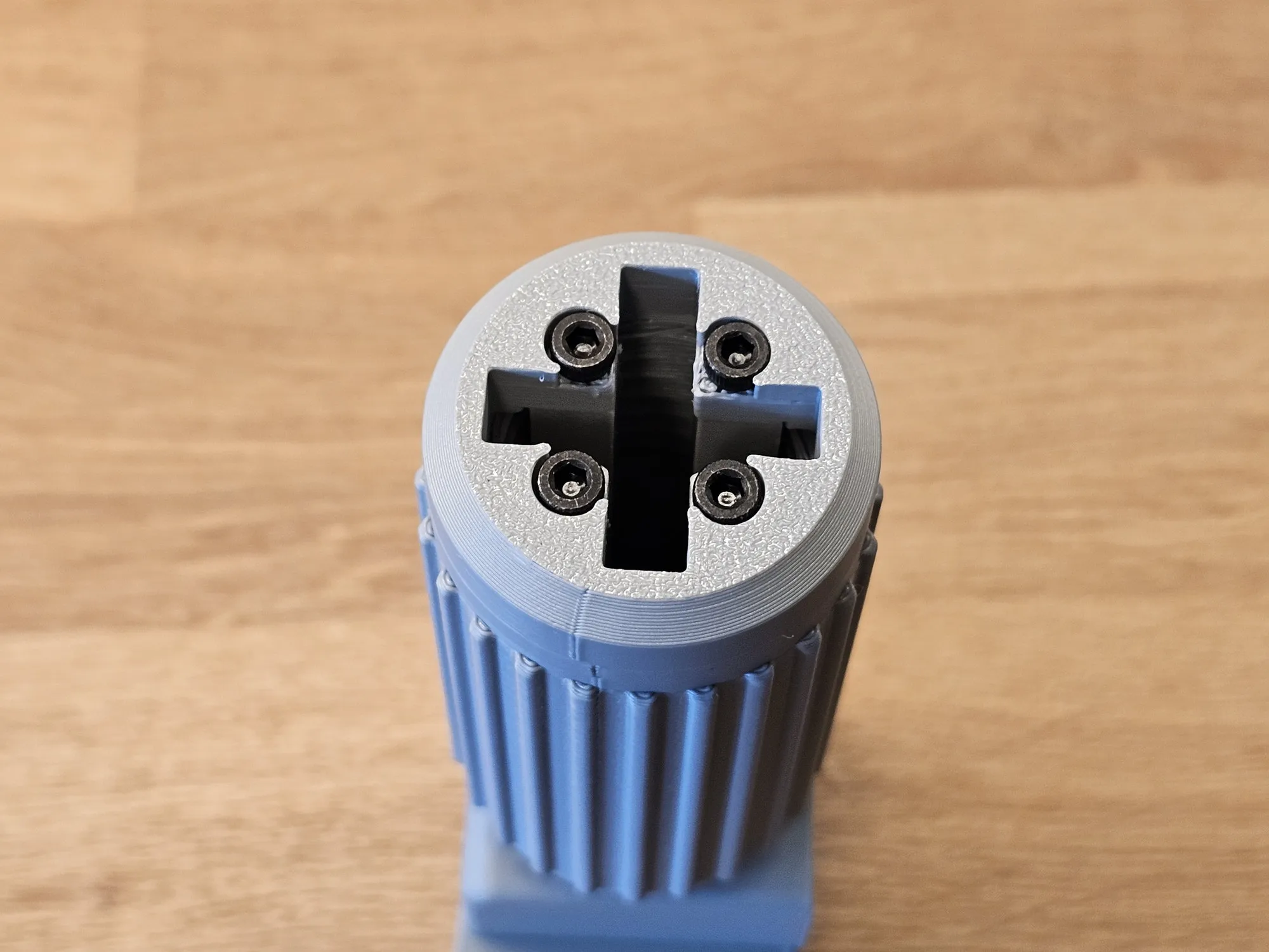
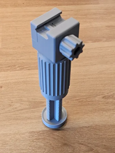
| Insert the foot and screw it in fully by rotating the main adjustment body. 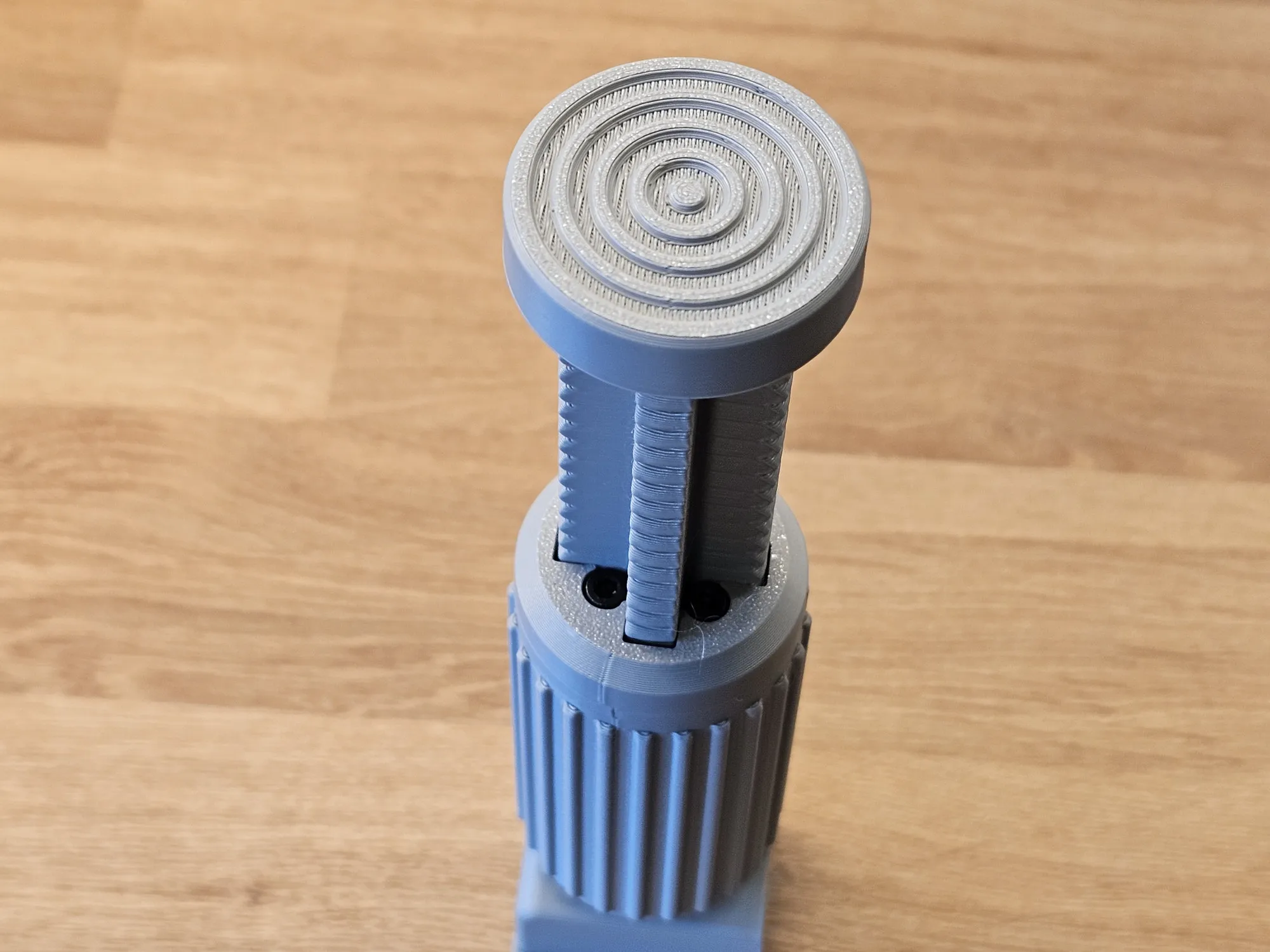 |
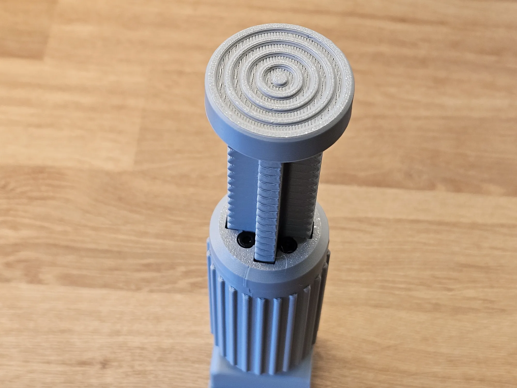 | Insert the M6 screw and prepare the nut. 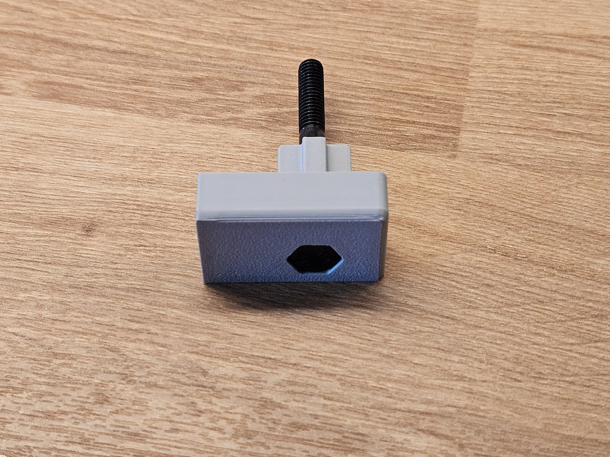
|
 |
 |
 |
 |
if you have any suggestions about this project, feel free to contact me !
Enjoy !
If you want to support my work:
Boost Me (for free)
If you like my work and want to see more, please consider boosting me. It would be greatly appreciated!
If you want to sell my models:
Membership
If you want to sell my projects, check out my commercial license !
Thank you so much for all your support!
License

You shall not share, sub-license, sell, rent, host, transfer, or distribute in any way the digital or 3D printed versions of this object, nor any other derivative work of this object in its digital or physical format (including - but not limited to - remixes of this object, and hosting on other digital platforms). The objects may not be used without permission in any way whatsoever in which you charge money, or collect fees.


Comment & Rating (10)