RPKeebs WK78 - TKL keyboard using SUO TX WK87 pcb

Print Profile(0)
Description
STATUS: ALL DONE
I am primarily on printables (https://www.printables.com/model/1612022-rpkeebs-wk78-another-tkl-keyboard) so updates are first and foremost over there, but I'll try to keep it updated here on Makerworld as well.
V5 of both 3.5 degrees and 5 degrees is fully tested.
Obviously, you need a 2-color large printer for this. or be creative with cutting into smaller parts and glueing. I am using a Prusa XL with 5 tools, but you would only need 2, 1 if you don't care for the transparency or print the whole thing transparent and paint where you don't want transparency.
My third keyboard project, this time based on a PCB I found on AliExpress.
"TX SUO TKL R PCB 1.2MM WK hotswap PCB"
Yeah, that's a mouth full.
So apparently, this is sold by TX Keyboards, is based on a WK87 in collaboration with LDN ... Yeah, I don't know any of those, but, here's the project.
The Board
The board is about 80 euro. Not cheap, but it has Hotswap sockets, addressable RGB for each key, 24 underglow RGB LEDs and 2 for status. The firmware is proprietary, Windows only, Windows software is chinese only and we all know how terrible these apps can be, but, it was surprisingly feature rich. No Mac support (key codes), no custom keycodes, no web-based software etc. But; it has an STM32F411CE chip and that is QMK compatible.
The Challenge
Engineering the firmware took about 8 hours and the plan was a little something like this;
- Beep out (multimeter) the rows
- Beep out the columns
- Beep out the LED pins
- Configure QMK
- Add VIAL (aka use the VIAL fork)
- Put the board in DFU
- Burn the firmware
- Done.
What actually happened;
- Step 1; Can I put the board in DFU mode?
Yes, we can; we short Pin36 VDD of the MCU to Pin44 Boot0 while powering up, and bam, in DFU. But this is a hassle, so I found two nearby easier-to-solder-on pins and soldered on a pushbutton. (Turns out, we would only need this once, so use tweezers, be careful, and you won't need to solder)

- Step 2; determine the rows
- I beeped out Escape through F7, then F8 was separate; well, an 8x12 matrix is possible, so let's continue
- F8 - Pause ; so far so good
- Tilde - 7, 8 - Home ... Wel, makes sense, PGUP would be 9th key, ...
- PGUP in a row alone ... That is a waste, but ok
- etc...
- Ended up with 14 rows.
- Step 3; determine the columns, how are they connected to the MCU
- None of the columns mapped to the MCU, which would not have enough pins for that, and I already spotted the shift register, and sure enough, 8 columns to the shift register.
- Thus I should have 14 pins on the MCU for the rows...
- Step 4; map the rows to MCU pins ...
- Only 12 pins beeped for rows ...
- Turns out, the PGUP (and some others) were not in a row by themselves, the rows wrapped around.
- Step 5; Configure QMK
- Normally I would build a ROW2COL layout, but the diodes pointed towards the switch from the COL side ... but a COL2ROW setup did not work either.
- And both sides of the switch were logic high (3.3v) That's not good.
- So I had to take out the scope; the shifter was mainly high, pulling low, so in fact, the COL2ROW was correct, but then the diodes were wrong ... So it must be ROW2COL
- Step 6; I needed a second opinion, so I asked Claude.
- Yes, the firmware config is AI assisted, but I vetted every line, it is all correct.
- Turns out; the shift register should be low mainly and pulling high, now each switch is low on one side, high on the other, but still, that should not be; one side should pull high or low, the switch should bring that signal to the MCU; one is output, the other input, and both seem to be output ...
- Well; the matrix of this board has rows and cols swapped. Does not matter a thing, other than confusing the H out of me. There are 8 Columns each with 14 rows, the Shift register is the output, through the diodes, to the switches, to the rows, into the MCU as inputs.
Success, a Semi working keyboard, because now all the keys are jumbled.
- Step 7; Debugging the matrix; I told Claude to build a test layout for each key to output an ASCII character, then unjumble based on a long list of "Escape = A, F1 = g, F2 = &". This worked remarkably well
- Step 8; The RGB matrix.
- An RGB matrix can use multicolor LEDs with shift registers for each R, G, B individually, but the crappy software already told me the LEDs were WS2812; serial data, easy peasy.
- The trick now to find the first LED. Would this be the LED marked "LED0"? Haha, NO!.
- The matrix starts at the arrow up, close to the MCU, then goes to right, down etc all the way to left control, then up to shift all the way to the right shift, then up to enter back to caps. So I told this to Claude. It took 7 (!!) tried for claude to understand the concept of snaking across from bottom to top, but in the end, the matrix was defined. 87 key LEDs, then 24 underglow LEDs and finally 2 status LEDs
- Unfortunately, I have not been able to use the underglow as separate LEDs with their own lighting effects, if anyone knows how I can have both RGB per Key matrix on 87 LEDs and underglow on the rest, let me know please.
Well, done... almost.
- Step 9; Status LEDs;
- LED23 = CAPS Lock LED. Why shouldn't we?
- LED24 = Layer indicator; off for layer 0, Blue for 1, Green for 2 (windows base), Yellow for 3.
- Step 10; The default keymap
- I created 4 layers, 2 for mac, 2 for windows
- Switching is done with FN+TAB
- I did not replicate the entire Keychron keymap, but that can easily be done with VIAL.
- Step 11; The 3D Model
THE WARNING
- Just because this worked for me, does not mean it will work for you. You are changing a product firmware to something not supported, things can go wrong, you will void your warranty. Nobody but you is responsible.
The programming procedure;
- Ensure you have all QMK tools installed, see their documentation on how.
- clone the Vial repo
git clone https://github.com/vial-kb/vial-qmk.git MyKBDProject ; cd MyKBDProject - clone my keyboard config repo
git clone https://github.com/rmpel/qmk-vial-keyboard-wk87.git ./keyboards/rpkeebs/rpwk87 - Insert USB cable in computer, and place it loosely (not connected) in the PCB USB-C port so you can insert with one hand. (PCB upside down, obviously)
- Have QMK Toolbox open so you can see when the DFU device is detected
With tweezers (and perhaps magnification) bridge pins 36 and 44, hold steady, plugin USB and when you see the DFU appear in QMK Toolbox, remove tweezers.


OR; solder two wires and a push button like this;

and push the button while attaching USB.
- First time you need to unlock the flash memory with (only once, then never again)
dfu-util -a 0 -s :unprotect:force - Build and Flash the firmware;
qmk flash -kb rpkeebs/rpwk87 -km vial - The keyboard will automatically exit DFU mode and the RGBs should come to life.
- From now on; when you need to flash, run the flash command and when asked push FN+ESC to go in bootloader mode. You can remove this using VIAL.
The 3DModel
I like keychron keyboards and have loads and I 3d printed 2 of those, but I wanted something different. Something brutalist, bare minimum, so first I thought
"Why not just a wedge and a plate"
But I did not like the bare PCB being exposed, so I added a rim.
- The top part is the plate, I made it thicker than a normal plate would be to give it less flex; PETG is quite flexible at 1.5 mm, I learned that the hard way.
- The bottom is still a wedge, with ridges that should (!) match up exactly with the hot swap sockets. This should give strength, stability and when printed in clear PETG, should diffuse the RGB underglow adequately.
I Designed the top to be multi-part. You can print it as one, but when using the multipart one, and split to parts, you can print 3 parts in clear, for the underglow and status LEDs
Drag both TOP parts to your slicer and answer "Yes" to the question if they are from the same part. Then you have two parts to color, one opaque in any color you like, the other transparent (or opaque if you don't care about RGB. Reminder that the status LED 'windows' are also part of this, so color accordingly.)
Assembly
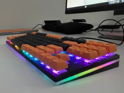
The assembly should be as follows; this is how I imagined it, but the print is not yet finished, once photo's of the keyboard are posted, you can consider this design finished.
- If you chose pcb mounted stabilisers, mount them now.
- If you chose plate mounted, mount the spacebar one now. The spacebar stabiliser is a hassle, but the closed gaps are needed for switch-stability, so mount it while you have all the wiggling room.
- With a bit of wiggling, you can thread the second stab housing through the gap from the bottom.
- Place top case top-down on desk (on a book or something if you have a stabiliser in place
- Slide PCB in, F row first, threading the USB port through the hole
- Drop in the pcb. Yes, this will be loose for now, i deliberately did NOT create any fastening.
- Insert the bottom wedge; the front (skinny) side has tabs (Like woodworking biscuits) that slot in the top case, then drop in the back
- Two M3x10 screws from the back hold it in place.
- Turn over, the PCB should drop down nicely on the ridges.
- Insert switches
- Add keycaps
- Attach USB chord.
Happy typing.
More information here; https://github.com/rmpel/qmk-vial-keyboard-wk87
Model was created in TinkerCad https://www.tinkercad.com/things/j2OqCod8cQN-rpwk87-brutalist-housing
Using the plate of an old project, this was created with OpenSCAD, but I can no longer find the link.
Everything in this project is created by myself, the QMK firmware configuration is AI assisted, but all code checked and cleaned up by me personally.
Comment & Rating (0)