FPV Gimbal -Print in Place- extended rotation angles


Print Profile(1)
Description
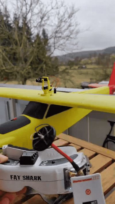
Hello FPV pilots
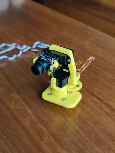
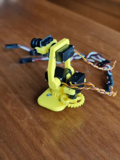
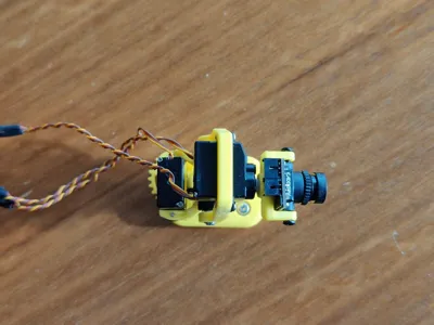
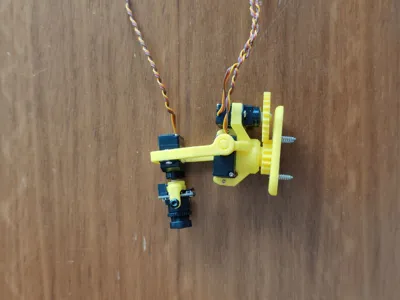
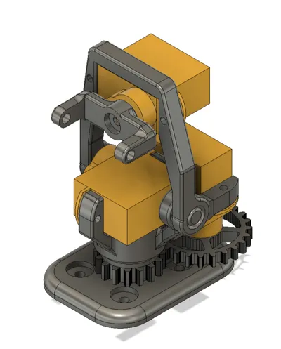
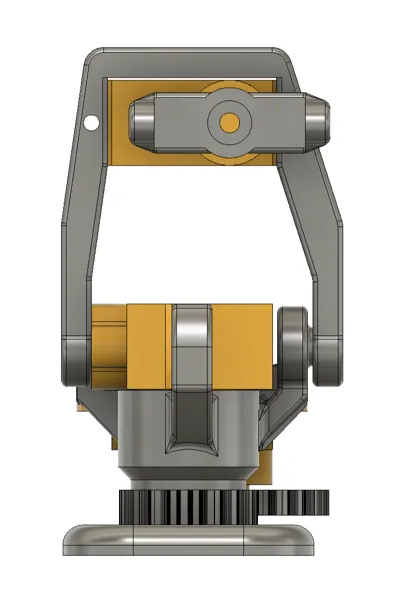
This is my second FPV gimbal, which has a slightly more compact design than my other model. This one is also compatible with the 2g servo from Torcster (https://torcster.de/Torcster-Nano-Servo-NR-40-Digital-22g). A CADDXFPV Ant camera is used. I believe other micro cameras with a width of 14mm should also fit. Additionally, the lateral movement (pan-axis/yaw) on this one is gear-driven. The gearing ratio is chosen such that the camera moves 50% more than the servo motor dictates, allowing for a wider field of view

I am aware of the function of a servo extender; however, since it didn't work with my servo, I integrated the gearing into the gears
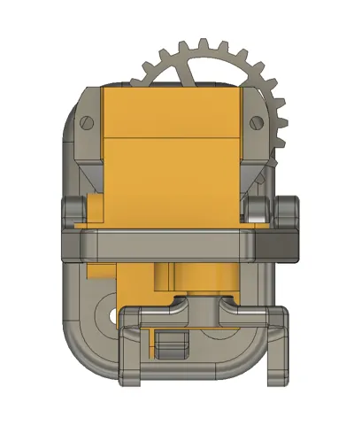
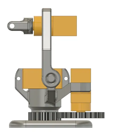
Unfortunately, printing and assembly are not entirely straightforward, but in my opinion, it is the best way to enable the assembly without additional bearings or similar components. A Print-In-Place bearing is designed for the yaw axis. This must be activated after printing. For this, the marked bridge (image below) beneath the outer bearing component must be removed with a knife or a thin saw. I recommend using a 0.2 mm nozzle, as the geometry, especially in the gear area, is very small and delicate. I have not tried it with a larger nozzle

Afterward, the bearing must be "freed up" by twisting. Due to the very small gap, both components might stick together. By twisting, the bearing can be loosened. However, to achieve the best result for different material manufacturers and printer and material calibrations, I have added different gap dimensions to the print file. The print plates are named after the gap size. With the first print plates (named "test"), only the bearing area can be printed to test the play and freeing-up. Once a good setting is found, the correct component can be printed with the corresponding gap. Finally, the remaining components must be printed on the last plate


Have fun with your build. Feel free to write me in the comments if I should integrate other camera models or if you have other suggestions
Boost Me (for free)
You can also leave me a boost
Comment & Rating (1)