


Print Profile(1)
Description
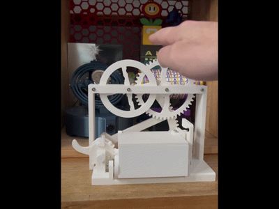
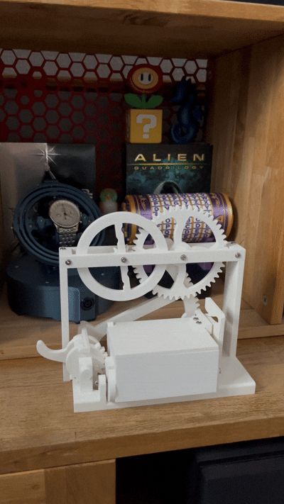
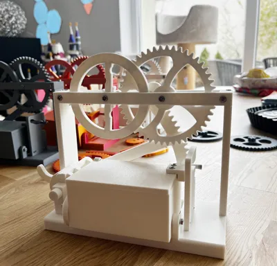
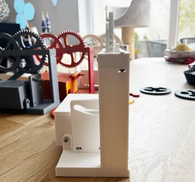
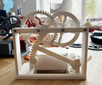
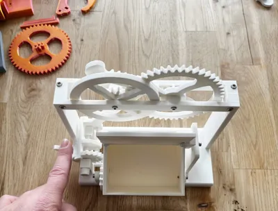
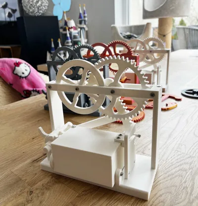
Automatic Gear Box – Mechanical Surprise Box
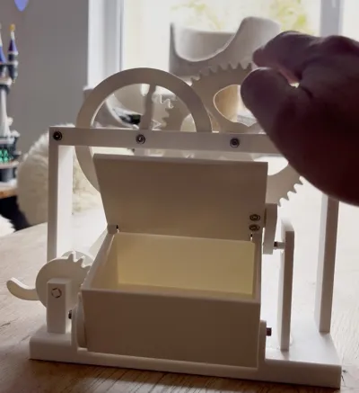
- This fully mechanical, gear-driven box was designed to combine visible mechanics with a playful surprise effect. The exposed gears drive an automatic lid-opening mechanism, allowing the functionality to remain clearly visible at all times. Inspired by classic mechanical curiosities, the model combines technical precision with a touch of nostalgic mechanical charm.
- All gears and mechanical components were specifically designed for this project and optimized for FDM 3D printing. PLA works particularly well for this model. Clearances have been carefully adjusted to ensure reliable and smooth mechanical movement — proper filament calibration helps achieve the best results.
- The assembly mainly uses standard M3 screws and nuts, making construction stable while remaining straightforward. Some screw connections should only be tightened lightly to ensure the gears can rotate freely. Certain parts can optionally be secured with a small amount of glue if desired.
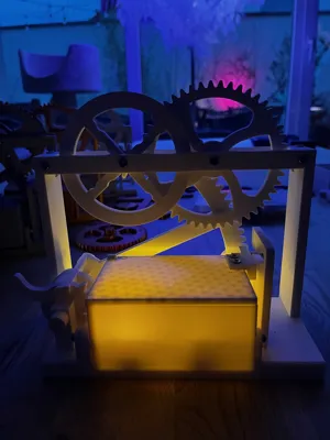
- This model is intended both as a decorative mechanical display piece and as a small technical experiment — ideal for anyone who enjoys visible mechanics, gears, and classic mechanical constructions.
For assembly, mostly M3 screws and nuts are used. The design is optimized to allow a stable yet uncomplicated build. A complete overview of the required screws can be found below.
Printing & Assembly Notes
The model is designed for printing in PLA. Proper filament calibration is recommended to ensure smooth movement and to prevent gears or moving parts from binding. The screws for the upper gears on the frame should only be tightened lightly so that everything can rotate freely. The wheel next to the large gear should ideally be secured with a second nut (counter-nut) to prevent the rear nut from loosening over time.
Required Screws Overview
- 3× M3×30 mm – 2× upper frame mounting + 1× for the large gear
- 1× M3×35 mm – counter-locking screw for the wheel (without teeth) on the frame
- 2× M3×6 mm – segment mounted to the box
- 2× M3×10 mm – pivot axles of the box
- 1× M3×16 mm – automatic lid opening mechanism
- 2× M3×18 mm – upper gear/wheel bracket to frame
- 2× M3×16 mm – guide wall mounted to frame
- 2× M3×8 mm – lid mounting
- 2× M3×6 mm – arm attached to the lid
🛠 Assembly - Video:

For best results, it is recommended to lightly secure the marked parts with a small amount of glue on the back side of the model.
🛠 Assembly Instructions
1. Assemble the frame
Insert 3× M3×30 mm screws at the top.
Secure one position with an M3×35 mm screw and a counter-nut.
2. Install the box
Mount the pivot axles using 2× M3×10 mm screws.
3. Mount the lid
Attach it using 2× M3×8 mm screws.
👉 Install the arm only after the lid is mounted.
4. Attach the arm to the lid
Use 2× M3×6 mm screws.
5. Install the automatic opening mechanism
Insert the M3×16 mm screw with the printed roller.
Tighten the nut only lightly so the roller can move freely.
6. Mount the gear segment
Use 2× M3×6 mm screws.
7. Attach the guide wall
Insert 2× M3×16 mm screws from bottom to top.
8. Install the gear/wheel bracket
Use 2× M3×18 mm screws from top to bottom.
⚠️ Important Notes
- Mount the lid first, then attach the arm on the lid.
- Some parts should be secured with glue.
Have fun building it! 🙂
Comment & Rating (2)