Random Length Wire Antenna 9.1 Xfrm with CMC Box


Print Profile(1)
Description
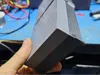
This is a Random Length Wire Antenna with a 9.1 transformer and a common mode choke assembly box.
Now the random part is not entirely random, it can not be a multiple or sized for the band(s) you are targeting. I made mine with just over 200 feet. This works on 80 to 6 meters quite well, even better with an antenna tuner. This does semi-work on 160 meters, but the wire is to long to be useful outside of just a few states. Your height above ground, distance between bends (if you have any) all affect performance. Your best bet is to look up the antenna see the popular sizes of wires and what it works and doesn't work on. There are 2 sizes that will work on all HF bands. Also the higher the better!
Mine is strung up about 30 foot and makes a big L shape plus the feed running up. I put the box on a metal stake just a few inches from the ground. I also made a small ground network as the counter poise. Keep in mind if you didn't all ready know, just driving a ground round or 2 doesn't make to much. RF is shallow! Several small generator or garden ground rods spaced at a rods length apart will work well. You can also add some radials. The wire itself, I just used some leftover 18 gauge wire.
Screws for the lids and dogbones are #6 6-32 and can not exceed ½ inch (half inch is recommend, but ¼ inch should work also). For the coax bulk head connection, follow the recommend size by the manufacture. The coupler can be 6-32 screws also, but they will likely need to longer, like 1 inch or some metric equivalent.
So the build…. Presuming you have experience and knowledge on RF transformers and chokes…
Also this box is not weather proof, by design! You should have it on its side (ground terminal down) or lid down so it can drain. I have never had a sealed hobby box actually keep water out. In-fact it seems to let it and keep it for life. This is design to breath as it will be an outside install. If you have a trusted weather tight box you are going to put it in, go for it.
- Print with PPS! This box will be outside and possibly see some high heat. Nylons could work, but be sure to paint them to protect against UV.
- Couple the boxes together using the coupler and 4 screws.
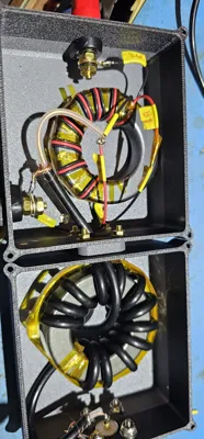
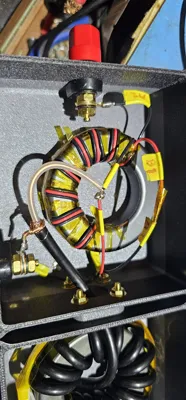
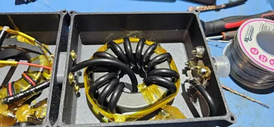
Use 22 gauge PTFE wire and wrap the 9.1 transformer. I used this wire https://www.amazon.com/dp/B0D21SRJHS Follow the M0UKD picture (this is an auto-transformer style). I also used a FT-250 Mix 31 core found here https://www.amazon.com/dp/B084JQ7ZK3 This part is important, substitution of any of the parts or not wrapping as shown will change (likely drastically) the performance {for the worst in most cases}.


You will need to stop the leads from flapping in the breeze. Something like this. Also secure it down by some means. I would recommend using non vinegar smelling silicone caulking. I used industrial glue, its not readily available to the consumer market.

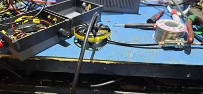
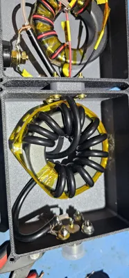
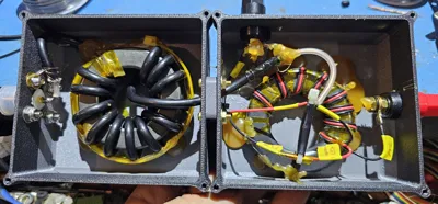
Use RG-58 (solid plastic core not foamed! [ https://www.amazon.com/dp/B0BB724CDG ]) and wrap very tightly 13 turns around it. Keep it neat and don't do any over under stuff. This is the common mode choke. Leave some leads on it, and secure this also with silicone.
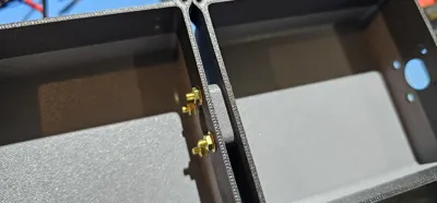
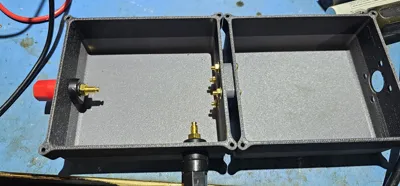
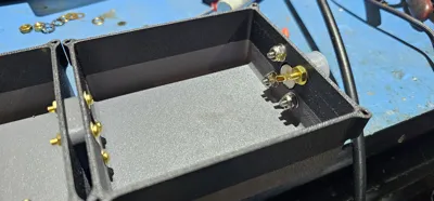
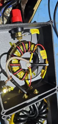
- The transformer box I just bought some cheap banana jacks and cut them. You could do this or brass bolts, eyelets, what ever you want. Just be sure you can know what is the antenna and what is the ground counterpoise and can bond the wires securely inside and out. Wire the transformer as the diagram showed, but instead of the “to radio”; that goes to the CMC. The ground lug gets transformer and output side of the CMC coax shield.
- Should note, this design does not need a static bleed resistor but lightning mitigation needs to still be applied.
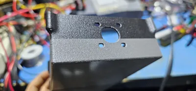
- Install the coax connector, odds are its the SO-239 bulkhead. You may have also notice, I use some brass screws as ways to put an eyelet on it to make the ground connections. I used these https://www.amazon.com/dp/B09231QNLF you can use what ever you want including the name brand. These almost all follow the same Amphenol bulk head connector footprint.
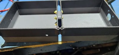
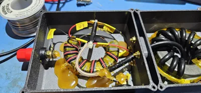
When you are all done, and not yet have it glued down it should look something like this. Keep in mind the transformer winding must be exact. The CMC you have some leeway on spacing. Mine you can see is shifted, that is me tuning it. Its not a major gain, but if you have the equipment you can squawk a few more db's out of it on most parts of the band.

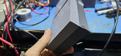
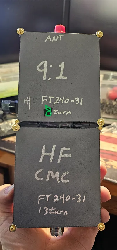
The covers are self explanatory and the dog bones are to support the 2 boxes; they go on the screws that are closes together between the 2 box's. Now for some results! In the following screen shots, I only had the landscaping shallow well point attached to the ground side of the transformer and it worked phenomenal. I also have conductive soil. I have expanded it and was able to get even more performance out of it; not night and day, but nothing to shake a stick at either. I have made over 11,000 mile confirmed contacts on this very thing on 20 meters. DX is not an issue on this.
This is HF SWR, with HAM band call outs. As you can see, some bands would need an antenna tuner for optimal results. The wire length will dictate what bands perform well and what ones don't. As state earlier look up the length tables when you make yours and determine what kind of setup you are going for. Bigger bonus if you have the equipment to tune!
Now several factors will determine radiation efficiency. In this chart, 160 meters is by far the worse, but don't knock 60 meters out as I can hit 4-8 thousand miles all night as the band allows. I run no more then a 100 watts at the radio. The peak efficiency is around 17 to 15 meter bands. The confused batt figure is the resonate of my 9.1 transformer. Changing core types will change these drastically. Do not use the “red cores”, my testing (since those are the most popular kind used in write-ups that don't have detailed testing) of cause the end users to have poor results and think of this as a garbage antenna. Mix 43 may offer better upper HF performance at the cost of lower HF performance; you may also cause more noise and less stability. Do not use the other mixs, as this will just cause poor performance; especially “red core”; but you don't have to believe me, try, test, log, graph and do a write up; that's half the fun of this hobby!

This is the CMC performance, transliterated to resistance on the 50 ohm system. Keep in mind you can make these better, but you will need more cores and equipment to tune and test with for development. The setup I show was the best single core broad band solution I could find. You can literly print another CMC box, lid and coupler and set of dogbones and double the filtering (its additive, so if you have 4, the resistance to CMC is 4x higher but keep in mind 2x is big change, 3x or higher is very minor with 5 being no measurable gain). Also a CMC is not optional with this antenna and quite a few more types. You do not want RF in the shack and the feed-line should not be part of your antennas radiator.

License
You shall not share, sub-license, sell, rent, host, transfer, or distribute in any way the digital or 3D printed versions of this object, nor any other derivative work of this object in its digital or physical format (including - but not limited to - remixes of this object, and hosting on other digital platforms). The objects may not be used without permission in any way whatsoever in which you charge money, or collect fees.
Comment & Rating (0)