
2U mini ITX motherboard 10"rack panel with PCIe
Print Profile(3)
Description
Boost Me (for free)
Like this model? Boost it! 🚀🔥
Thanks for supporting my work! 🙏
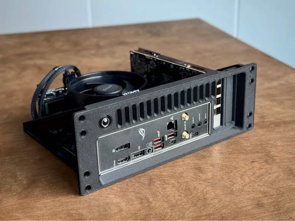
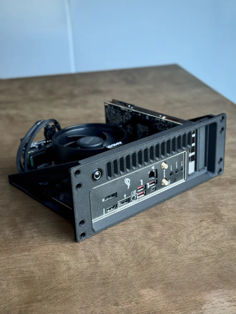
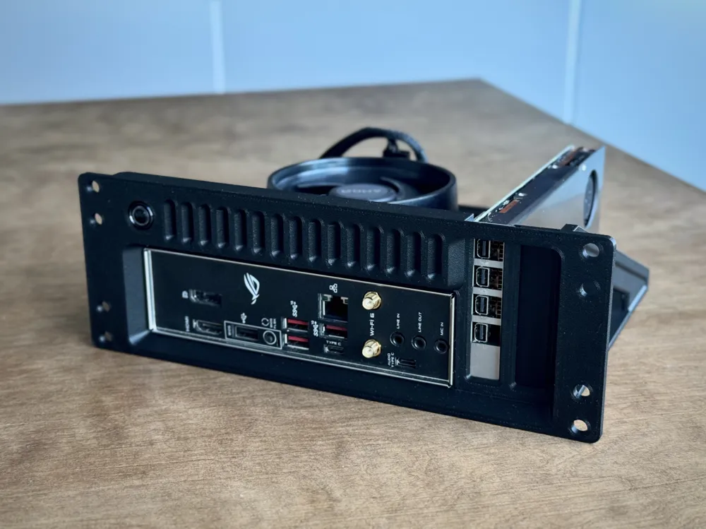
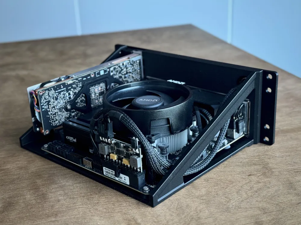
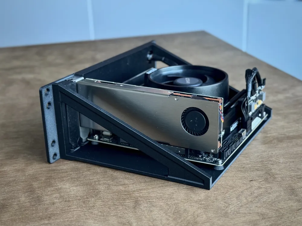
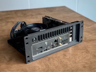
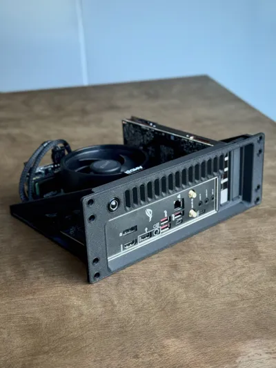
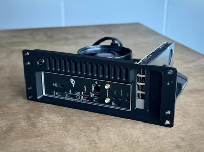
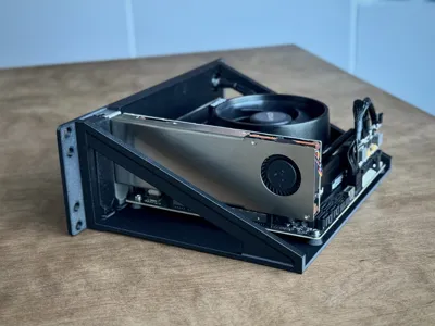
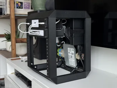
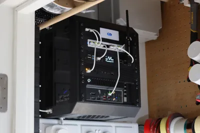
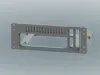
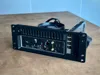
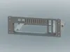
This is a 10-inch rack panel for Mini-ITX systems, designed to keep things compact and practical. It supports a double low-profile PCIe card, which makes it a good fit for network cards, GPU, or similar expansion hardware in homelab or small server setups.
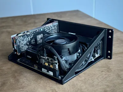
There is an opening under the motherboard to access the CPU cooler mounting points and the bottom NVMe slot found on some ITX boards. That means you can swap coolers or drives without tearing the whole system apart.
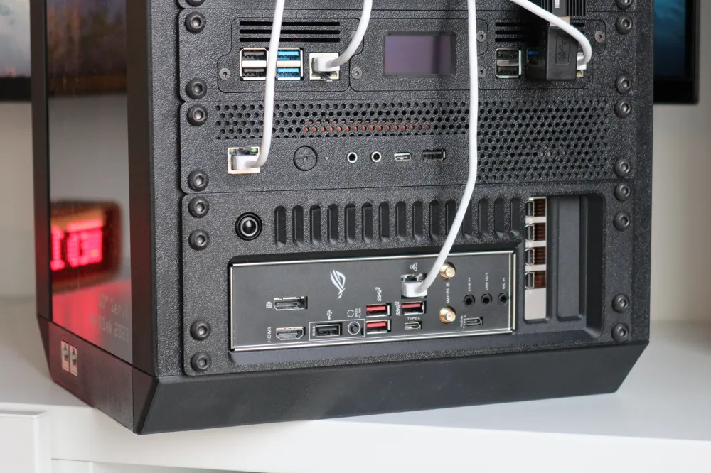
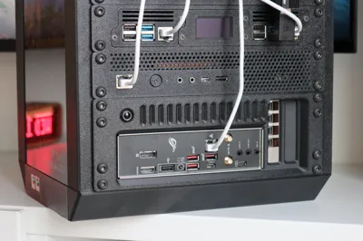
The front panel has a 12 mm mounting hole for a push button, intended for a power or reset switch - no support needed there, just use a scalpel to finish the hole.
The model was designed to print cleanly with very little support. For the best surface finish, the support interface is printed in PLA, which comes off easily and leaves a much nicer result on visible areas. The main part is printed in PET-G / PET-G CF
Hardware required for assembly
Motherboard
- 4× M3×6 heat-set inserts (4.2 mm OD)
- 4× M3 screws
PCIe brackets
- 2× M3×3 heat-set inserts (4.2 mm OD)
- 2× M3×3 button-head screws
Variants
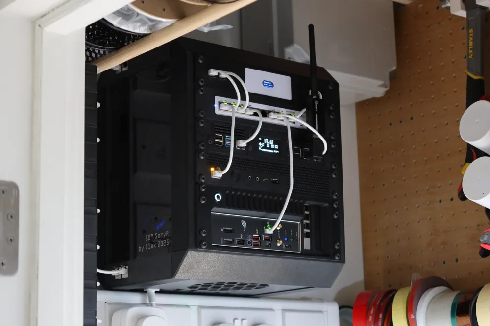
- Standard - as seen in the photos. Vertical slots are for decoration only - I control the flow and pressure through my rack with filtered fans on top and bottom.
- Open Vents - Vertical slots above the IO plate are open for easier ventilation
- Keystone - added a place for two keystone jacks next to the power button.
Print Settings
- The print profile file has been optimised to achieve the best quality.
- Use PLA or support for PET-G material as an interface layer to print in the best quality.
- If changing parameters, please pay attention to purge volumes - I suggest at least 700 mm3 when changing from support to part material.
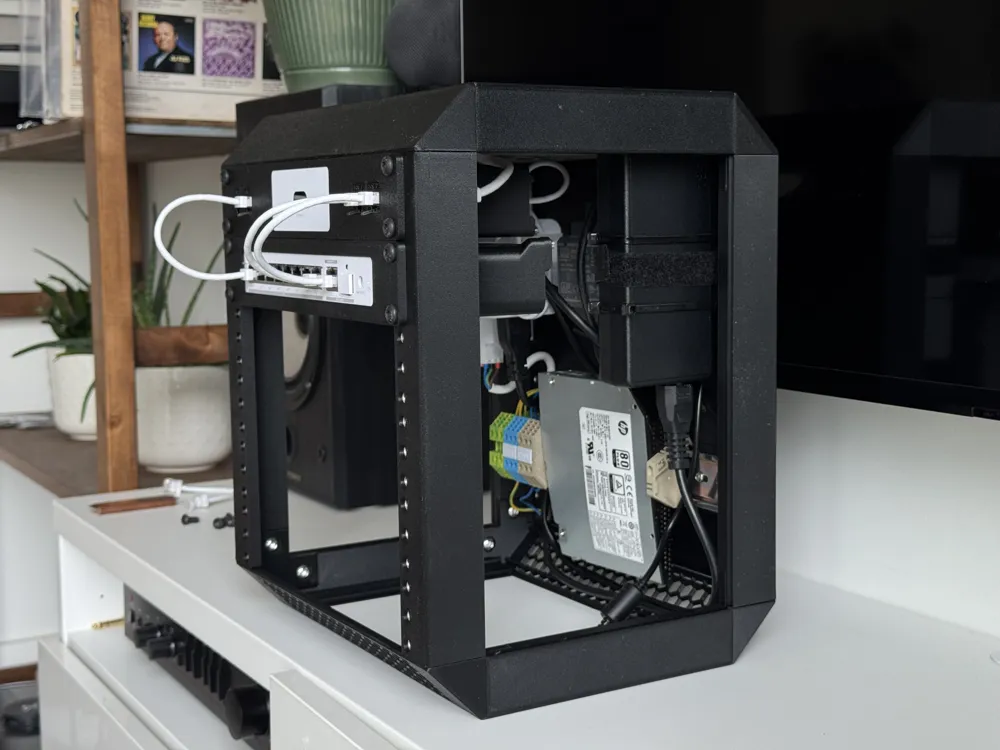
In my case, I power the board with a “PICO PSU” type power supply. It is inserted in a 24-pin connector on the motherboard and powered with a 12V power supply installed in my rack.
This panel is meant to be nice-looking, solid, and easy to work on once everything is installed.
License

You may create derivative works based on this object, provided that all such derivative works are published exclusively on the MakerWorld platform and include proper attribution to the original creator. You may not share, upload, host, distribute, or publish this object—or any derivative work of this object—on any other digital platform, marketplace, or distribution channel. Commercial use of this object and any derivative works is strictly prohibited. This includes, but is not limited to, selling, renting, sublicensing, or using the object in any context in which you receive monetary compensation or other financial benefits.


Comment & Rating (44)