Mini Orca V3 80mm EDF Jet


Print Profile(1)


Description
Table of Contents
- Introduction
- Flight Video
- Design Process
- Airplane Specifications
- List of Materials and Electronics
- Assembly Guide
- CG, Rates and Expo
- Summary
Boost Me (for free)
Like this project? Consider boosting me!
INTRODUCTION
If you are reading the following content on the Chinese version of Makerworld, please note that the content might be automatically translated. I will not be able to reply to your comments on the Chinese version of Makerworld because I do not have a Chinese account.
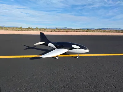
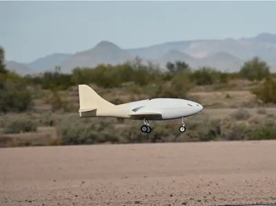
Introducing my latest design - the Mini Orca 80mm EDF Jet. This high-performance EDF jet served as the payload airplane for my personal research project on aerial airplane launches (see picture below), and I am now happy to release it as a stand-alone airplane that anyone can build and fly. The current design is my third revision of the airplane. It now features retractable landing gear, flaperon control surfaces, a larger wing area, and a significant weight reduction compared to previous versions. Using a high-performance 80mm EDF motor on a 6s LiPo battery, you can easily get more than a 1:1 thrust-to-weight ratio to perform aerobatics. This airplane is designed with neutral stability in mind, therefore it is not recommended for beginner pilots. This jet can fly fast - easily more than 100 mph, however it can also fly slowly with the flaperon setup. Stall behavior is gentle, and the airplane can quickly recover from a stall. No gyros or flight controllers are required to fly this jet.
All components of this airplane can be printed on a Bambulab P1S 3D printer; larger printers can reduce the number of plates, but it is not necessary to complete the build. Feel free to ask me any questions in the comment section. I will try my best to reply to everyone as fast as I can. I hope you enjoy the build!

Flight Video
Currently, I do not have a flight video of the V3 Mini Orca EDF. I will update this page once someone records a flight video for me.
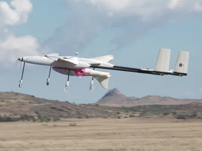
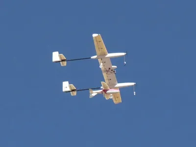
For now, you can enjoy an aerial-launch demo completed by my carrier plane (also fully 3D-printed), with the V2 Mini Orca EDF jet as the payload.
Design Process
The aircraft's shape was designed in NASA OpenVSP. You can request access to my OpenVSP design file using the link below:
https://drive.google.com/drive/folders/1hpABlGr4PijBnDE_iz8Wz-3oMNUXZ5iO?usp=sharing
To download OpenVSP, you can use the link below to their official site:
After defining the aerodynamic shape, the model was analyzed using three software:
- xflr5: 2D airfoil analysis at different Reynolds number conditions: takeoff/landing, low speed cruise, high speed cruise
- VSPAERO: full airplane lift and drag analysis at different airspeeds
- Altair FlightStream: lift and drag analysis, static and dynamic stability, performance at different orientations (sideways, upside-down, etc.)

The airplane's aerodynamic center and CG location are determined using FlightStream, and a static margin of 15% was selected.
The detailed CAD design was completed after the aerodynamic analysis. The software used was CATIA V5.
Airplane Specifications
Below are some important airplane specifications for your reference:
| Mini Orca V3 EDF Jet Specifications | ||
| Wing Span | 1268.50 mm | 49.94 in |
| Wing Area | 24.94 dm2 | 386.57 in2 |
| Wing Loading | 120 g/dm2 | 2.46 lb/ft2 |
| Wing Cube Loading | 24.07 | |
| Length | 1200 mm | 47.24 in |
| Flying Weight | 3000 g | 6.61 lb |
| Airfoils | NACA Airfoils (Check with my VSP file in the previous section) | |
| CG Location | 95 mm AFT of leading edge at wing root (balance the plane using my included CG tool) | |
| Control Surfaces | Elevator, Rudder, Flaperon | |
List of Materials and Electronics
The following is a list of materials and electronics I used for my build. If you want to use different materials or electronics, feel free to download the full assembly stp file (at the bottom of this page) and make any modifications you would like.
3D Printing Filament
In the following picture, all components in White Color are recommended to be printed using Bambulab's ASA Aero filament. All components in Red Color are recommended to be printed using regular ASA material or other high-strength, non-foaming material. It is possible to print using other materials; you will need to experiment with the printing process.
All hinges for control surfaces are printed out of TPU 95A (plate 25)

Carbon Fiber Tubes
Main Wing Tube: 12mm x 10mm x 430mm, 2 pieces
https://www.amazon.com/dp/B00RX7GURU?ref=ppx_yo2ov_dt_b_fed_asin_title&th=1
Main Wing Rear Tube: 10mm x 9mm x 1000mm, 1 piece
Fuselage Center: 14mm x 12mm x 175mm, 1 piece
https://www.amazon.com/dp/B08ZN3DB8W?ref=ppx_yo2ov_dt_b_fed_asin_title&th=1
- Please note that the main wing tube needs to be inserted into the fuselage center tube for the removable wing.
- The main wing rear tube should NOT be glued in place; it needs to be removable
Aileron, Vertical Stabilizer, and Wing Tip Tubes: standard carbon fiber spine 300 arrow shafts (about 7.6mm diameter)
- These will be cut to the correct length when building. An alternative is to use 8mm carbon fiber tubes; you might need to enlarge the holes on the model to fit the 8mm carbon fiber tubes
Horizontal Stabilizer Tube: 5mm x 3mm x 73mm, 2 pieces ; 5mm x 3mm x 160mm, 2 pieces
Elevator Tube: 5mm x 3mm x 180mm, 2 pieces
Fuselage Center Joiner: 5mm x 3mm x 80mm, 2 pieces
Retractable Landing Gear
Main Gear: Freewing 80mm Avanti S V2 landing gear with retract, left and right
Nose Gear: Freewing 90mm EDF Ares 3D nose gear, OR the Freewing 80mm Avanti S V2 nose gear with retract
https://www.motionrc.com/products/freewing-90mm-edf-ares-3d-nose-landing-gear-fj32311081
- The plane is currently designed to use the 90mm Ares nose gear. If you want to use the Avanti's nose gear, you will not need to print the servo riser (plate 17), and you will need to trim the nose gear hard mounts (plate 17) 6mm shorter.
Electronics
EDF Motor: XFly Model 80 mm EDF, regular or the pro version
- No other EDF motors were tested. If you use other brands' motors, they are not guaranteed to fit, and some modifications to the airplane might be needed
ESC: 100 - 130 amp ESC, with cooling fan
Spektrum Avian 100 Amp Smart ESC
Spektrum Avian 100 Amp Smart ESC
- My airplane does not have the best cooling for the ESC. A cooling fan on top of the esc is recommended
- I also tested the ESC without a cooling fan; it seems to be fine, but runs a bit hotter
- The XFly 80mm EDF Pro version pulls 135 amps at full throttle at my setup. Be careful of ESC overheating
Battery: 6s 4000 - 4500 mAh Lipo battery, high C rating
- Using smaller batteries, such as a 6s 3300mAh, is possible. This can result in a light airplane with better performance; however, flight time will be reduced
Servos: Standard 9 gram high torque servo
- It is Highly Recommended to use stronger servos for the flaperons, with around 5 kg · cm of torque
- More budget-friendly servos can be used for all other control surfaces
Receiver: 8 channels required for all servos to run on individual channels
Control Horns: Nylon control horns
Additional Hardware:
M2 x 150mm fully threaded rods
Assembly Guide
Here's a step-by-step assembly guide. If you have questions about the build, feel free to reach out in the comments. Be aware that I can only see and respond to messages sent to the international version of MakerWorld.
As a reminder: All parts in white in the slicer are recommended to be printed in ASA Aero or other lightweight foaming material; all parts in red in the slicer are recommended to be printed in regular non-foaming material.
---------- Step 1 ----------
Start with the fuselage AFT sections (plate 2), print and glue the two pieces together using super glue (CA glue). There are no alignment features, so do your best to align the two pieces as well as possible.


When you use my print profiles for ASA Aero filament, you may notice some stringing (see picture above). This is a normal behavior, and the stringings can be easily removed using sandpaper. The printed part should NOT have any surface defects such as holes or delaminations. The layer adhesion should also be strong and not brittle
---------- Step 2 ----------
Print out the EDF bracket and hard mounts (plate 11 ), and the EDF top/bottom hatches (Plate 3). Align and glue them to the fuselage AFT sections. Glue the engine hard mounts to the EDF bracket. Note the orientation of the pieces; they should only fit in one direction. If you are uncertain about the engine hard mount's orientation, use the EDF motor to help with alignment.
Print two 10mm diameter cylinders, 25mm long, from any material. (right click empty plate > add primitive > cylinder, and then adjust the dimensions using “Scale” tool ). glue them like the following. They will help align with the fuselage center section later.


---------- Step 3 ----------
Now this is a good time to insert the servo cables into the fuselage AFT sections. You will need three sets of servo cables to control three servos. You can combine all the power cables and ground cables together to reduce the number of cables. Make the cable Extra Long! You don't want to realize that the cables are too short later.

---------- Step 4 ----------
Print out the fuselage center section, fuselage front section 1, and section 2 (plate 15,16,18). Insert the two 5mm x 3mm x 80mm carbon fiber tubes into the fuselage center section, then glue all pieces together.


---------- Step 5 ----------
Print out all vertical and horizontal stabilizer sections (plates 4 and 5), and insert the required carbon fiber tubes and arrow shafts.


Install the servos by connecting the cables, powering and centering them, and then gluing them into their slots. Finally, glue the vertical and horizontal stabilizer to the fuselage AFT sections. When gluing the horizontal stabilizer, push downwards at the location indicated by the arrow in the left picture. This ensures that the horizontal stabilizers are properly aligned. DO NOT glue the tip sections of the horizontal stabilizer yet! This will be done in the end after installing the control surfaces.


---------- Step 6 ----------
Next, we will build the main wing. Start by printing all pieces from plates 6-10 and plate 13. Assemble all pieces like the following. Do not glue the rear 1000 mm carbon fiber tube in place; it should be removable, and will be assembled in the end. We will use M4x10mm heat-set inserts and M4x10 nylon screws to secure the wing later.

Insert the arrow shaft into the wing tips, make it stick out about 40mm, then glue them to the rest of the main wing sections.


Print out the main wing fuselage joiners (plate 12), and insert the 14mm x 12mm x 175mm tube and the 10mm x 9mm x 1000mm main wing rear tube, as shown below. DO NOT glue any of these tubes in place; they need to be removable!

Slide the main wing along the rear spar and connect to the fuselage center section, check for fit and alignment. If the carbon fiber tube does not fit, you might need to remove some material using sandpaper. The main wing should slide onto the fuselage center section with minimal friction. If everything aligns and fits well, glue the wing fuselage joiner in place. Use small drops of glue to fit it in place, then remove the wings and the rear tube. Finally, use more glue to secure the wing fuselage joiners. This prevents the wings from accidentally gluing to the fuselage.

Flip the airplane around and install the landing gear aileron servo mount. Do not glue it in place yet. Insert the servo and the landing gear retract, check the fit, and then glue the mount in place. The little notch on the mount indicates forward direction. In the end, install the servo and the landing gear.

---------- Step 7 ----------
Next, install the EDF and the ESC. The EDF should only fit in one direction! If you are having difficulty closing the bottom hatch, try flipping the EDF to the other side (it turns out that the little mounts on the sides of the EDF motors are not perfectly centered). Before closing the bottom hatch, make sure the EDF motor spins in the correct direction. Also, double-check that the motor can spin freely without any of its blades grinding. Finally, print out the rear section fillers (plate 23) and close the hole. The ESC sits on the top internal surface of the center section. I first applied some thick double-sided tape to the ESC, then superglued it to the fuselage.

---------- Step 8 ----------
Print out the hatch sections (plates 19 and 20), and glue the two pieces together on a flat table. Insert and glue magnets to the holds on both the fuselage front sections and the top hatch. Be careful about the polarity of the magnets. Print out the battery strap mounts (plate 24), and glue them to any position you like inside the fuselage. Finally, install the receiver and connect all cables. You can see my setup below.

Print out some small tabs (20mm x 10mm x 1.2mm) from any material, and glue them to the fuselage as shown in the following picture. This prevents the hatch from deforming and falling off mid-flight.

---------- Step 9 ----------
Finally, print out all of the control surfaces (plate 1). Use carbon fiber tubes and arrow shafts to join the sections together. Use a flat table to help with alignment! Be aware that the orientation and the order of the pieces matter! When you align the pieces side by side, there should not be any gaps or discontinuities between the sections. See the following picture for part organizing. If you are unsure about the order of the pieces, you can always download my CAD files to check them.

Print out the TPU hinges, and then glue the control surfaces to the rest of the airplane. Do not use too much glue; the control surfaces should be able to move with minimal resistance. Use sandpaper as needed to remove materials and prevent pieces from interfering with each other.
Use Masking Tape to secure the pieces before gluing, especially with the tip sections of the horizontal stabilizers. Do not glue them together backwards!
Congrats! You should now have the entire airplane assembled! The only thing left is to install all control surface linkages.
CG, Rates and Expo
Aileron High Rate: 12mm up/down measure at the tip, 20% expo
- DO NOT use too much aileron travel! This airplane is very sensitive in roll!!
Elevator High Rate: 16mm up at tip, 15% expo. Use as much down travel as needed, be careful, and do not let the elevator hit the fuselage at full downwards deflections.
Rudder High Rate: 17mm left/ right, 15% expo
Takeoff Flap: 10mm down, with 1mm rudder left/right mixing to left/right aileron input
Landing Flap: 17mm down, with 2mm rudder left/right mixing to left/right aileron input
To check CG, print out the CG tool (plate 14), insert a screw into the hole on the tool, and install it around the main wing spar as shown below with the wing partially disassembled. The plane should balance level, when picking up from the CG tool.

Summary
It has been a fun and challenging year for me. I for sure learned a lot about 3D printing, airplane design, and building techniques. I still remember that I bought my first 3D printer two years ago - the Bambulab P1S, and I am very proud of all my achievements over the past two years! I'm not sure what I will be doing in the future or how long I can continue supporting my projects (I still don't have a stable full-time job). By the way, team “Jet Research” was actually just me by myself this entire time. Overall, I am very happy about my learning, and I wish everyone a Happy New Year! I hope you enjoyed my project!

- Jeb
License
You may create derivative works based on this object, provided that all such derivative works are published exclusively on the MakerWorld platform and include proper attribution to the original creator. You may not share, upload, host, distribute, or publish this object—or any derivative work of this object—on any other digital platform, marketplace, or distribution channel. Commercial use of this object and any derivative works is strictly prohibited. This includes, but is not limited to, selling, renting, sublicensing, or using the object in any context in which you receive monetary compensation or other financial benefits.
Comment & Rating (24)