
Heltec V3 Case 2x18650 Switch - multiple options
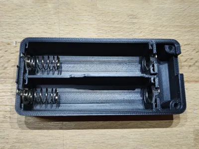
Print Profile(3)


Description
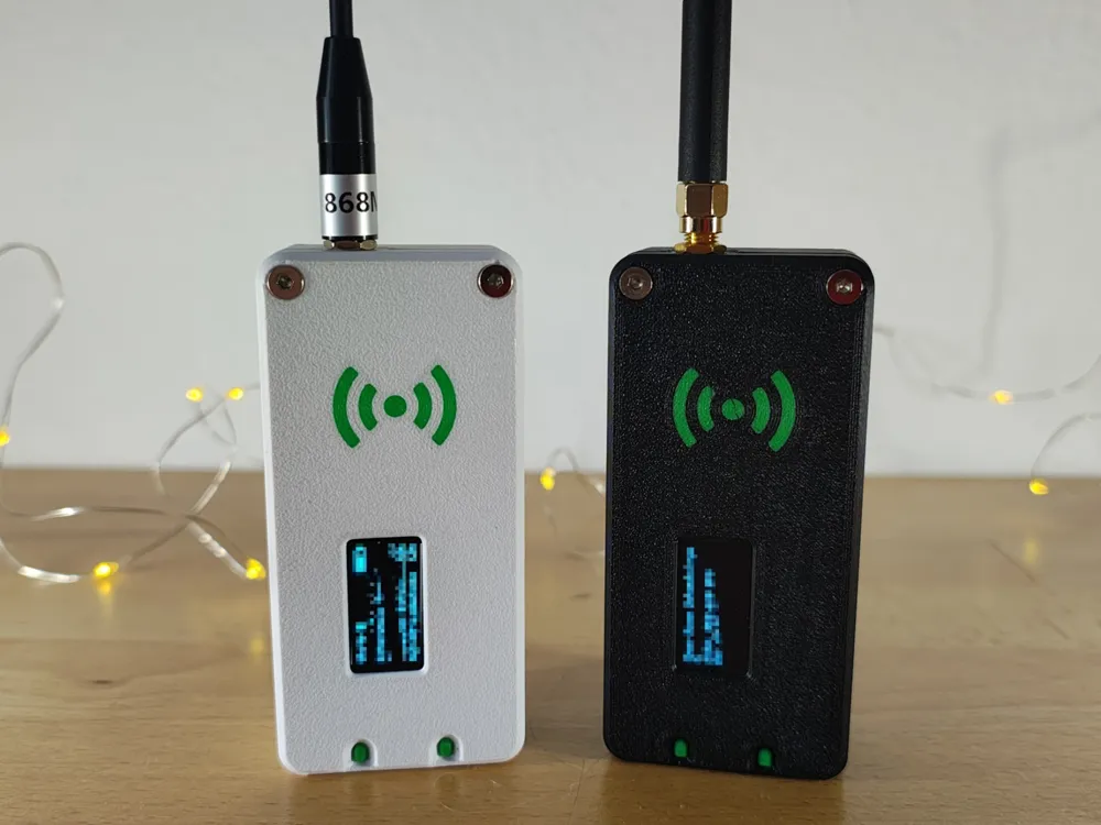
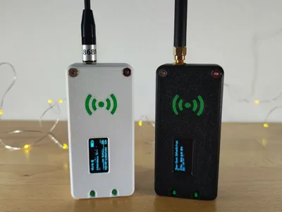
HeltecV3 LoRa case – 2 x 18650 LiPo
Update: 17 January 2025
Two more options have been added, both of which have a power switch so that you can turn the device off and on again to conserve power if necessary.
New version for classic spring-loaded battery contacts.
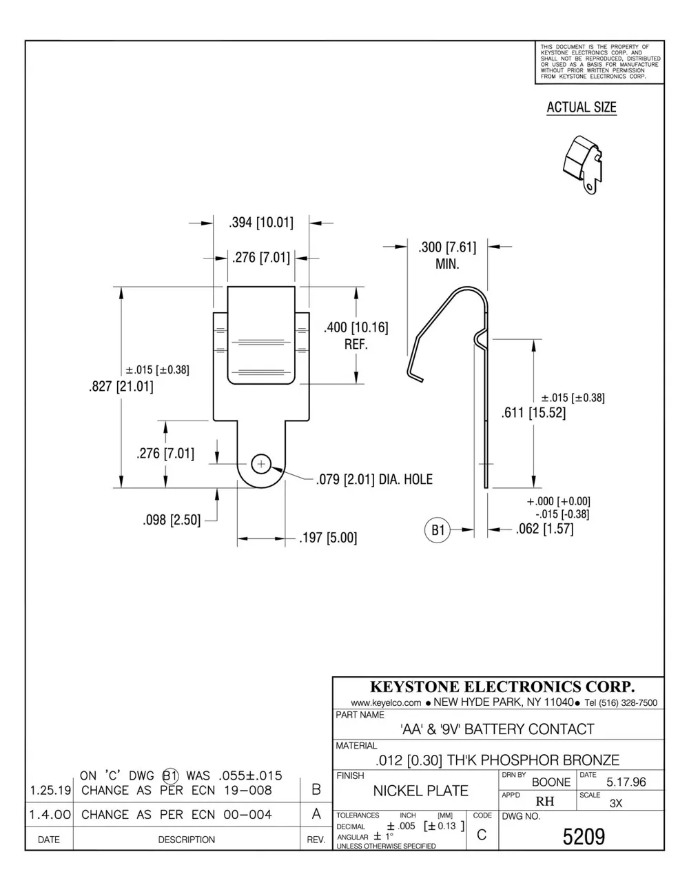
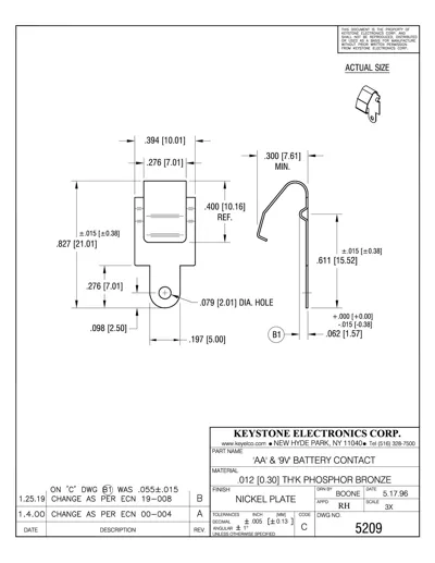
New version for Keystone battery contacts — see attached pictures.
All versions:
- Classic: no power switch, 16 mm spring-loaded battery contacts, 95 mm height
- Classic V2: power switch, 16 mm spring-loaded battery contacts, 100 mm height
- KeyStone: power switch, KeyStone 5209 battery contacts, 100 mm height
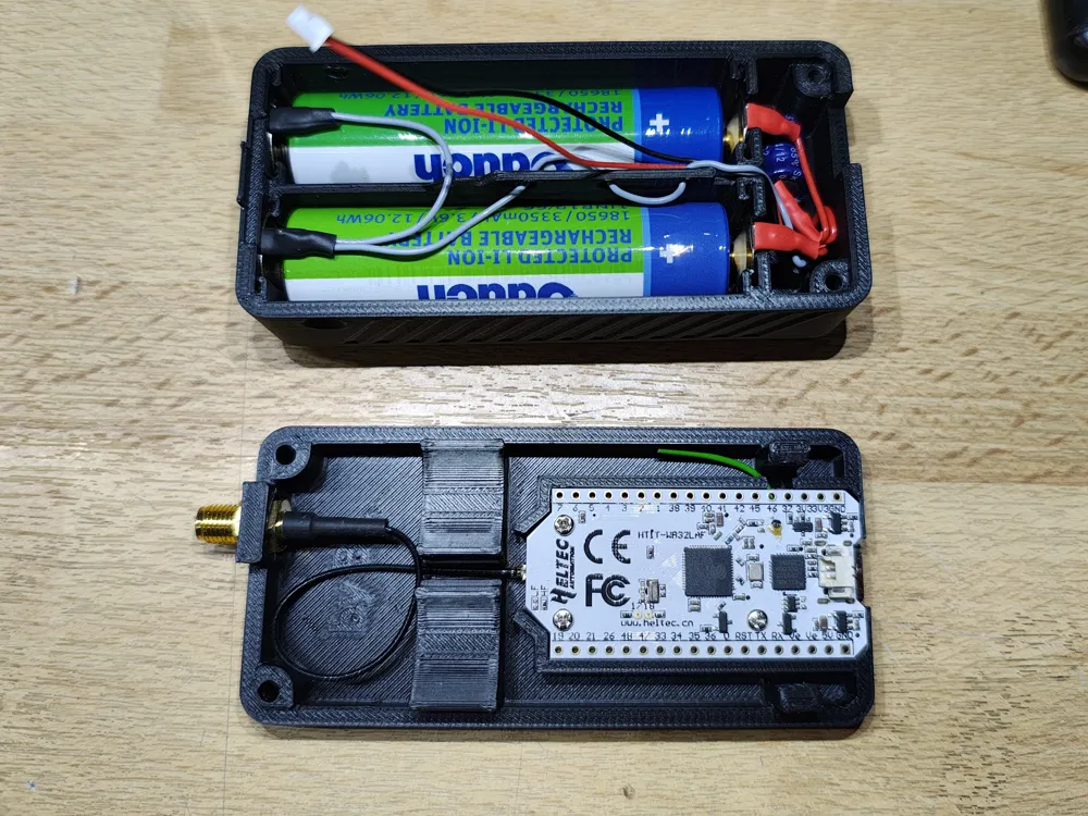
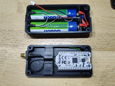
This case is designed for the HeltecV3 LoRa development board, which is commonly used for MeshCore or Meshtastic. The case features two compartments for two protected 18650 lithium battery cells. It is designed to be rugged and simple to use, with deeply recessed buttons to prevent accidental pressing when tossed in a backpack. The large battery capacity of around 24 Wh will provide power for 32+ hours, depending on the firmware and usage. This makes it great for taking on a trip, as you won't need to worry about charging it during the day.
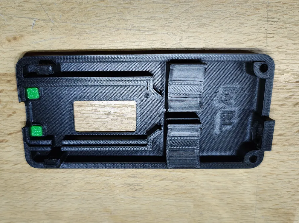
The case is printed without the need for support or multicolour or multimaterial. Multimaterial is only used for cosmetic purposes, to make the case look better.
Required parts:
- 1 x battery compartment (3D printed – use PETG)
- 1 x Heltec compartment (3D printed – use PETG)
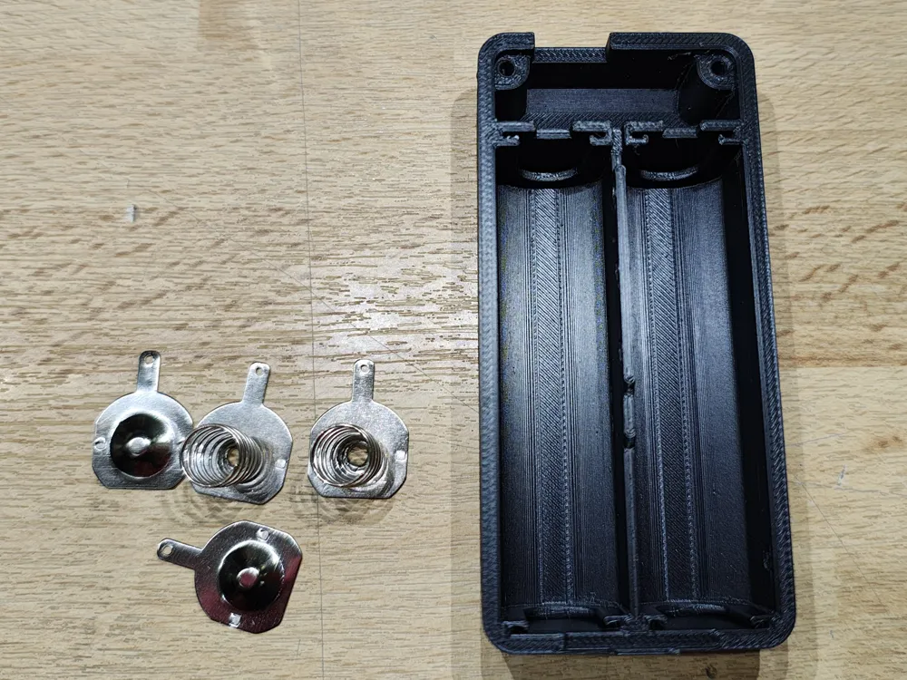
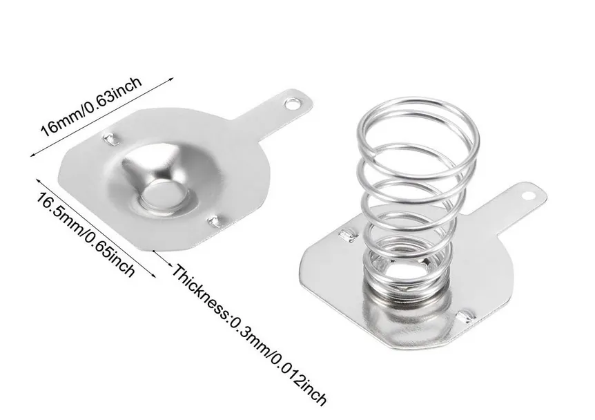
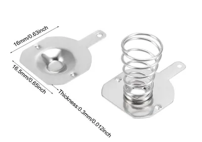
- 2 x sets of 16 mm battery contacts (search for 18650 battery contacts – a picture of the dimensions is attached)
- 2 x 18650 LiPo batteries – I recommend the protected version
- 2 x M3 x 6 countersunk socket head cap screws (DIN EN ISO 10642)
- 2 x M3 x 20 countersunk socket head cap screws (DIN EN ISO 10642)
- 1 x electrolytic capacitor 6.3 V, 100 µF or greater (not strictly necessary, but helpful if the unit is dropped and the batteries lose contact for a split second)
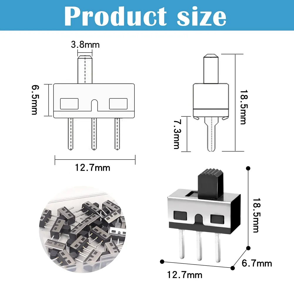
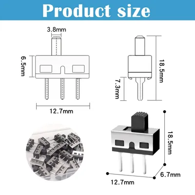
- 1 x switch SPDT, 1P2T
1 x Heltec V3
- 1 x SH1.25x2P male power cable
- 1 x IPEX to SMA pigtail
- 1 x LoRa antenna
- A little thin wire and heat shrink
Tools required
- M3 tap (use self-tapping screws if unavailable, but I strongly suggest using a tap).
- Soldering iron + solder
- Wire cutters
Assembly
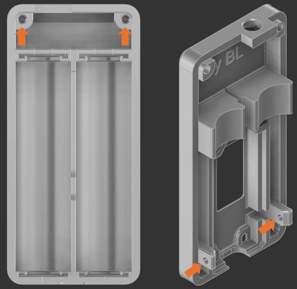
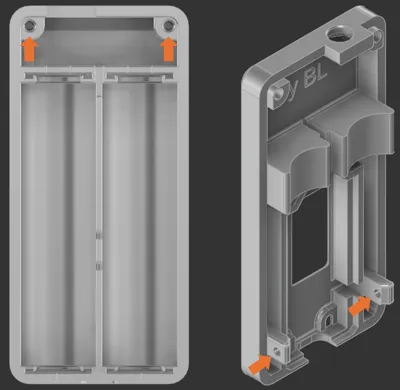
- Step 1: Tap the M3-marked holes.
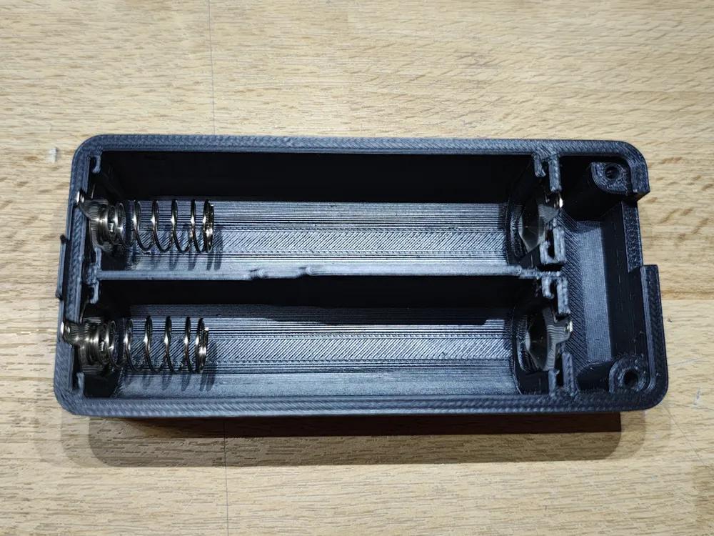
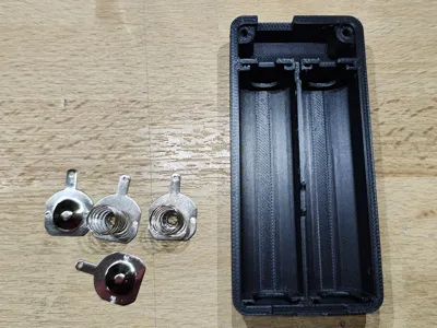
- Step 2: Insert the battery contacts. If you have trouble pushing them in, squeeze the indentations on them slightly (they will still sit very securely even if they are fully flat). Make sure you push them all the way in.
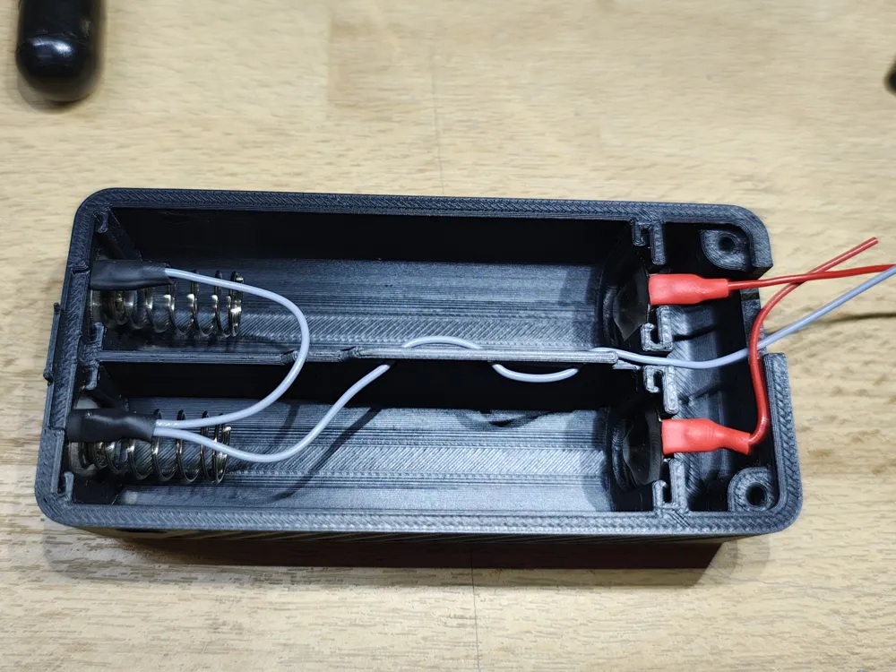
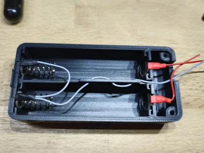
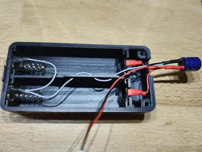
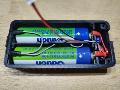
- Step 3: Bend the soldering tabs over and solder some wires onto them. Follow the diagram: grey is minus and red is positive. Insulate all connections with heat-shrinkable tubing! Take care when applying heat for soldering and shrinking as the plastic can melt.
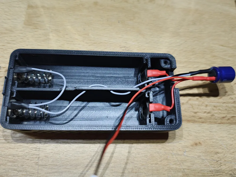
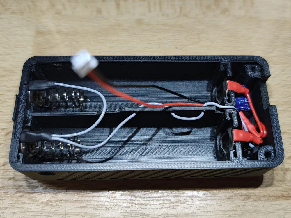
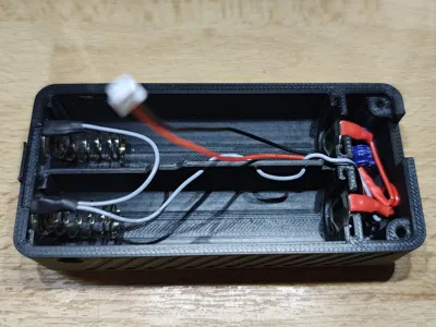
- Step 4: Connect the capacitor. Solder the grey minus cable and the cable from the black SH1.25x2P connector to it. This should go to the capacitor pin marked 'minus'. Connect both red plus cables and the cable from the SH1.25x2P power connector to the positive side of the capacitor. Use heat shrink again! - For the Switch version, place the switch between the red power line and the SH1.25x2P power connector.
- Step 5: Hide the capacitor away.
- Step 6: Measure the voltage of both batteries. They need to match very closely (less than 0.1 V). Do not continue if they differ by more than this! Fully charge or discharge both batteries and then continue.
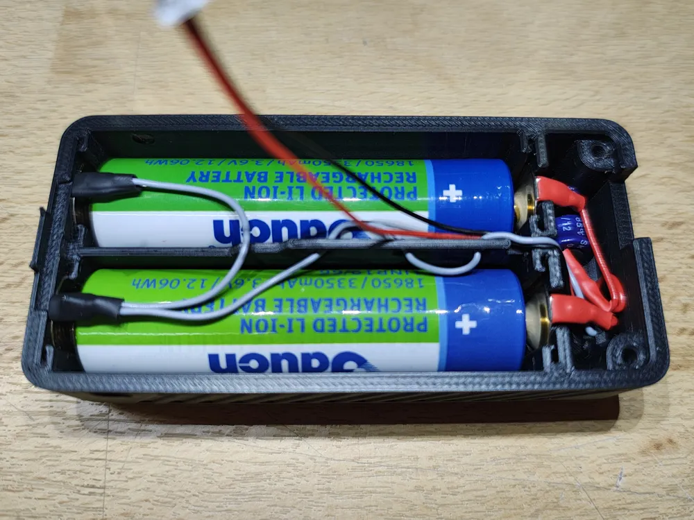
- Step 7: Insert the batteries, making sure to get the polarity right.
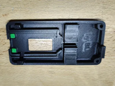
- Step 8: Insert the buttons into the Heltec compartment. They should fit in easily, but as they are very small, you may need to use tweezers.
- Step 9: Connect the pigtail to your Heltec V3.
- Step 10: Insert the Heltec into the Heltec compartment and give the buttons a quick test.
- Step 11: Secure the SMA connector.
- Step 12: Attach an antenna!
- Step 13: Connect the Heltec to the power source.
- Step 14: Close the case.
- Step 15: Use the M3x6 screws for the sides and the M3x20 screws for the top.
- Step 16: Enjoy!
Note: This case does not leave much room for other cables or a GPS module, so it is only suitable for a bare bones Heltec V3.
License



Comment & Rating (8)