Parametric Pull Out Rack


Print Profile(1)
Description
Boost Me (for free)
Please boost me if you appreciate this design. It really helps. Many thanks
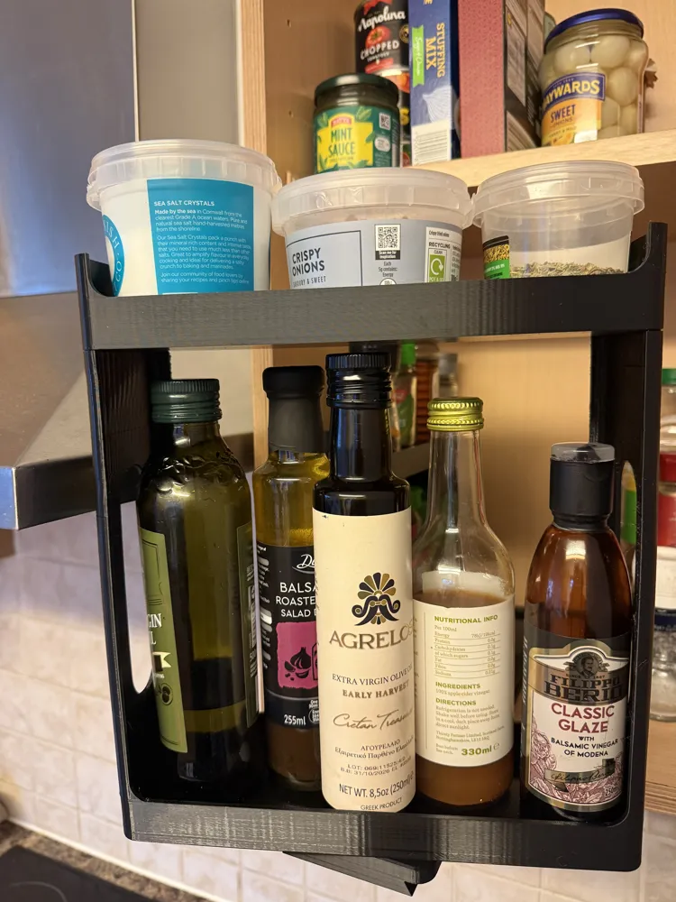
I've seen a few spice racks that have a similar pull out design but unfortunately none of them quite worked with my cupboard or jar dimensions. So I went about designing my own that can easily be set to any cupboard or jar/bottle size using parameters. All clearances, such as enough space above the jars/bottles has been accounted for to be able to lift them in/out. All you need are the dimensions set out below.
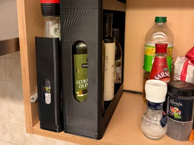
The rack simply slides forward enough to clear the cupboard and then has the ability to pivot to allow you to view and pick out whatever you're after.
No extra hardware is required for the assembly of these racks but you will need three screws per rack to fix it into the cupboard. I'm not sure I would trust double sided tape for this job depending on what you're planning on using the rack for.
You'll have to excuse the print finish on the large rack in my photos as I didn't have the correct settings for my PETG applied.
I've chosen to print this with PETG for added strength but I would imagine PLA would work just as well. I'll test PLA soon to confirm though.
I've also included the raw .f3d file if you'd prefer to make changes to the parameters or model directly in fusion but its relatively simple to customise the model directly from your web browser by just pressing customise in the print profile box above.
Customisable Sizes
The racks size is determined by four main parameters -
- Cupboard Height - The total height available in your cupboard. From the base to the first shelve or from shelve to shelve.
- Cupboard Depth - The total depth of the cupboard. Front face to the back of the cupboard.
- Jar Diameter - The diameter or width of the largest object you'd like to fit on the racking.
- Jar Height - The height of the tallest object you'd like to fit on the bottom rack. This will set the height of the first tier of the rack.
There is also the ability to change the size of the screw holes to suit what ever screws that you happen to have in order to fix the base plate into the cupboard. This is determined by three parameters -
- Screw Head Diameter - The diameter of the screw head. The part you insert the screw driver into, just to save any confusion.
- Screw Thread Diameter - The diameter of where the thread is, including the thread itself.
- Screw Head Depth - This is the height of the screw head including the countersink part. So from the top of the screw to where it finishes tapering to the screw thread, I hope this makes sense.
One last parameter that is required is what bed size your printer is. This will allow the model to automatically adjust its length to still allow it to fit on the print bed -
- Select 1 if your printer has a build plate size of 256x256mm, such as the Bambu P/X series printers
- Select 2 if your printer has a build plate size of 350x325mm, such as the Bambu H series printers
Importing File and Printing
When you export the file I'd suggest exporting as a .3MF file. This way the preset settings for strength will be applied in bambu studio. You can then import the file into bambu studio by selecting - File - Open Project - Then your downloaded .3MF file.
Once the file is open follow these steps to prepare it for printing -
Right click the model and select split - to objects. This will split the model into their individual components.

2. Select Auto Orient from the top menu. This will lay all the components correctly for printing.

3. Select Arrange all objects with Auto rotate for arrangement ticked.

4. This is how the objects will now be arranged and would be fine to print like this but I suggest arranging them as shown in step 5.

5. Add another plate from the top menu. Then drag the three smaller components to their own plate. The final arrangement will look like the picture below.

Assembly Instructions
The assembly couldn't be simpler but one tip i would give is to actually start of screwing just the base plate into place in the cupboard first and then unscrew it. This will make screwing it down with the rack assembled much easier.
The base plate will need to placed no further back than 5mm from the front of the cupboard. The back of the base plate is the part with the dovetail connection.
The rack with the centre hole is fitted on top of the slider with the slot in it using the threaded pivot. Ensure the threaded pivot is fully tightened so that no thread is showing. This is then slid into the base plate with the three screw holes and then the back stop can be slotted into the dovetail. The top shelf can then be placed on top of the bottom rack. It could be worth glueing the top shelf on if you find the fitment a bit loose.
The whole assembly can then be screwed down into the cupboard.
I really hope it all works out for you and any feedback would be greatly appreciated. Enjoy your tidy cupboard!
License
You shall not share, sub-license, sell, rent, host, transfer, or distribute in any way the digital or 3D printed versions of this object, nor any other derivative work of this object in its digital or physical format (including - but not limited to - remixes of this object, and hosting on other digital platforms). The objects may not be used without permission in any way whatsoever in which you charge money, or collect fees.
Comment & Rating (7)