
Packintosh SE - Mini-ITX PC case
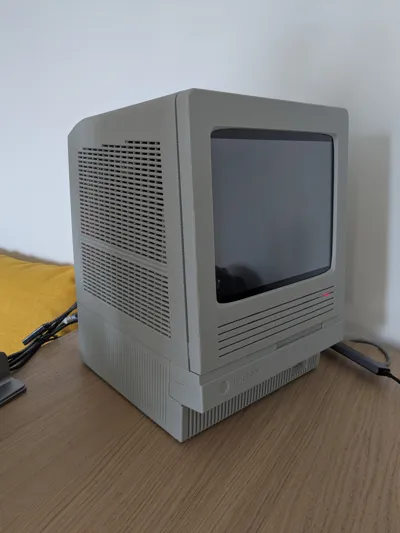
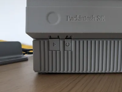

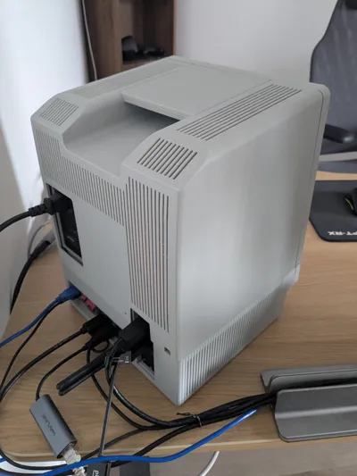
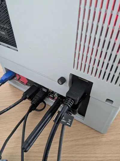
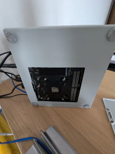
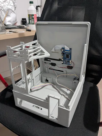
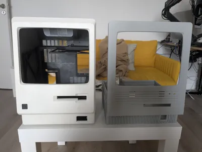
Print Profile(2)

Bill of Materials

Description

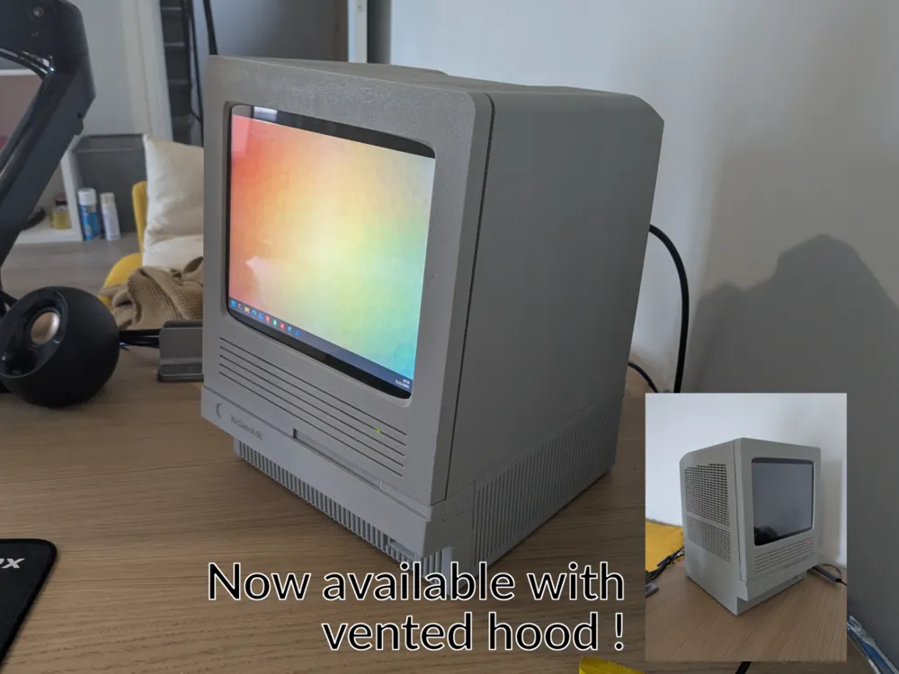
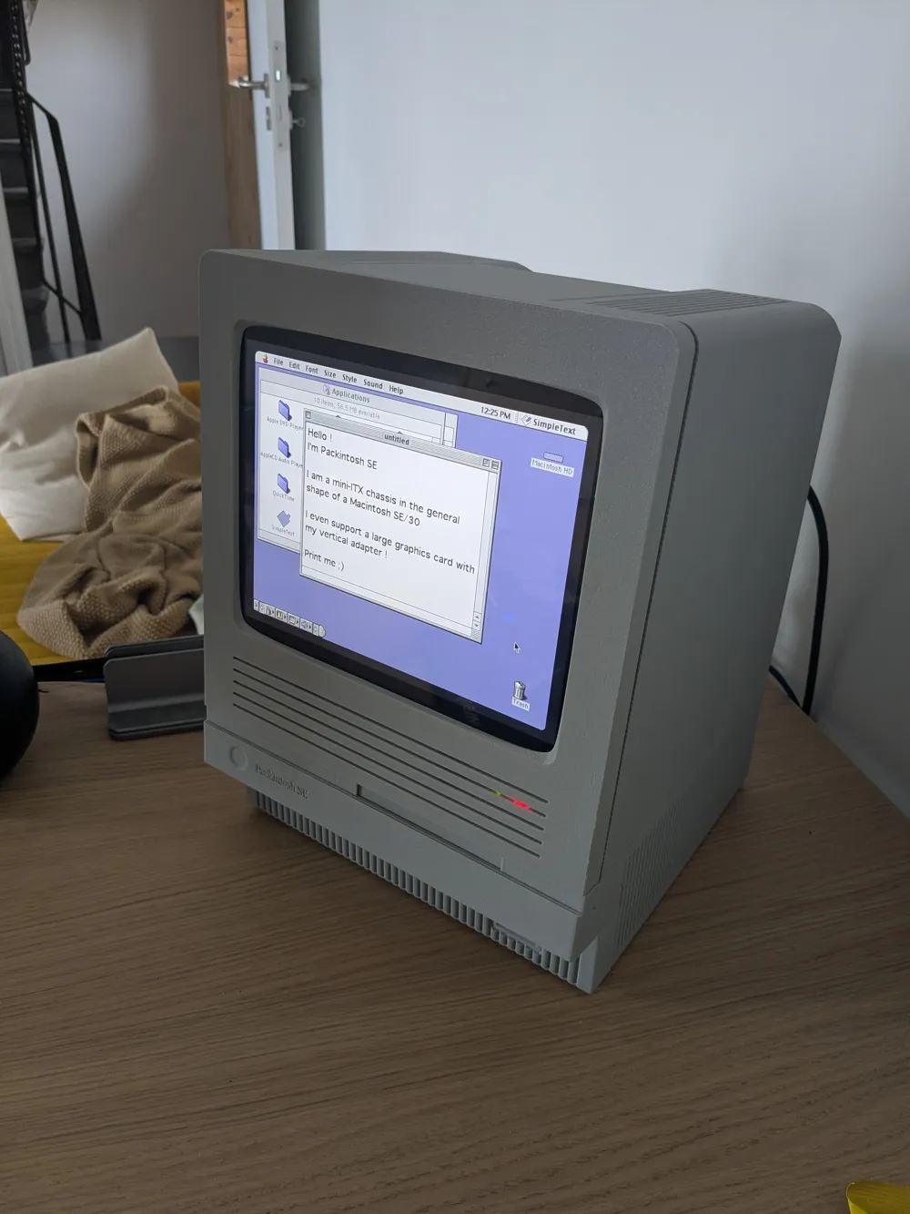
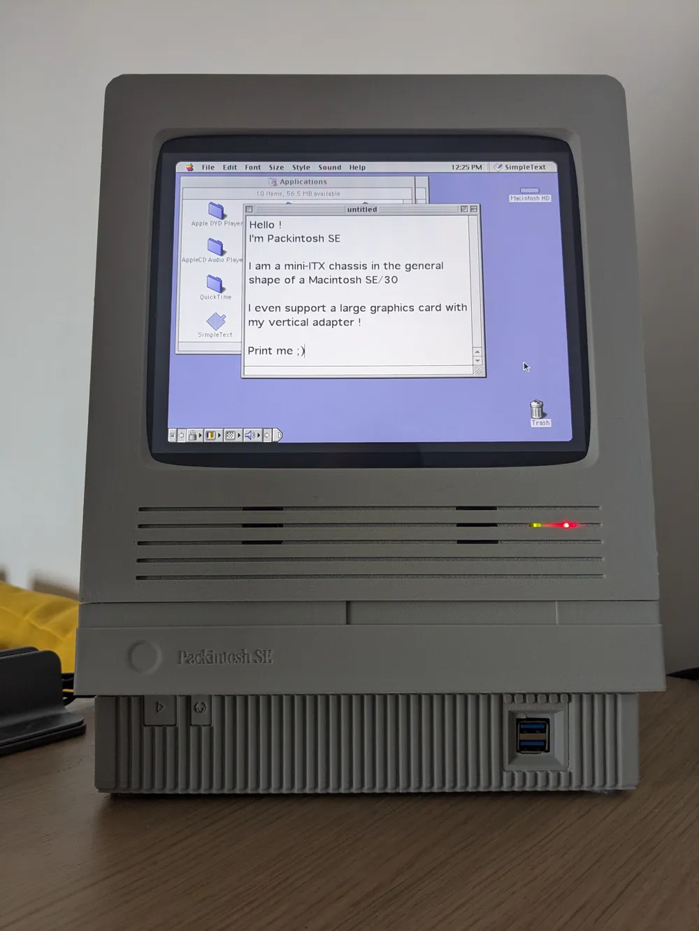
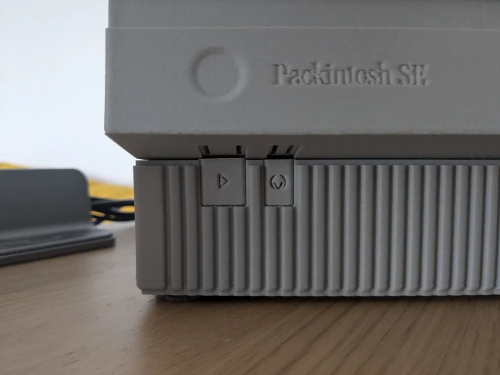

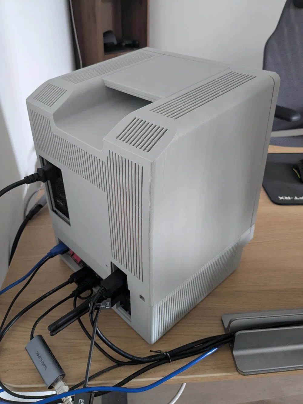
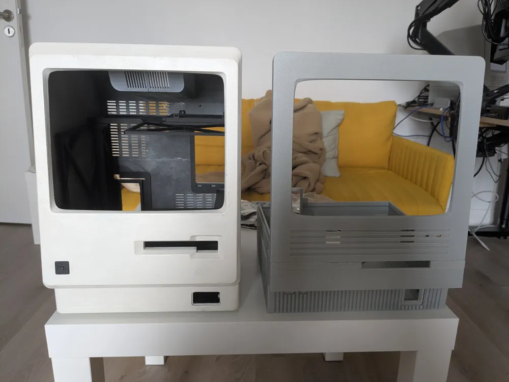
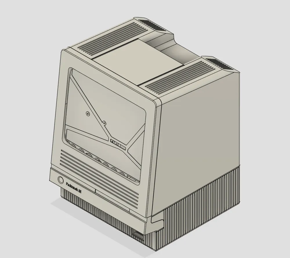
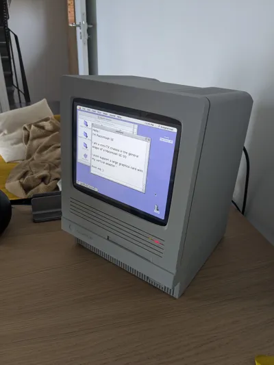
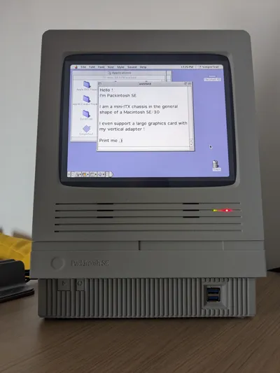
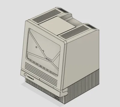
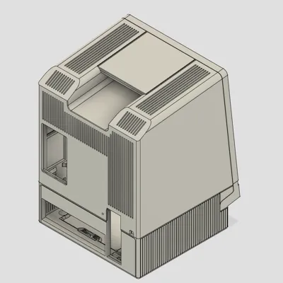
Meet Packintosh SE : a mini-ITX enclosure for PCs inspired by the legendary Macintosh SE and SE/30
Features
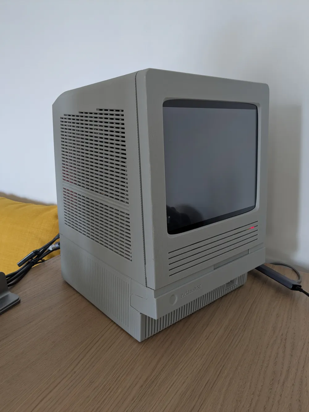
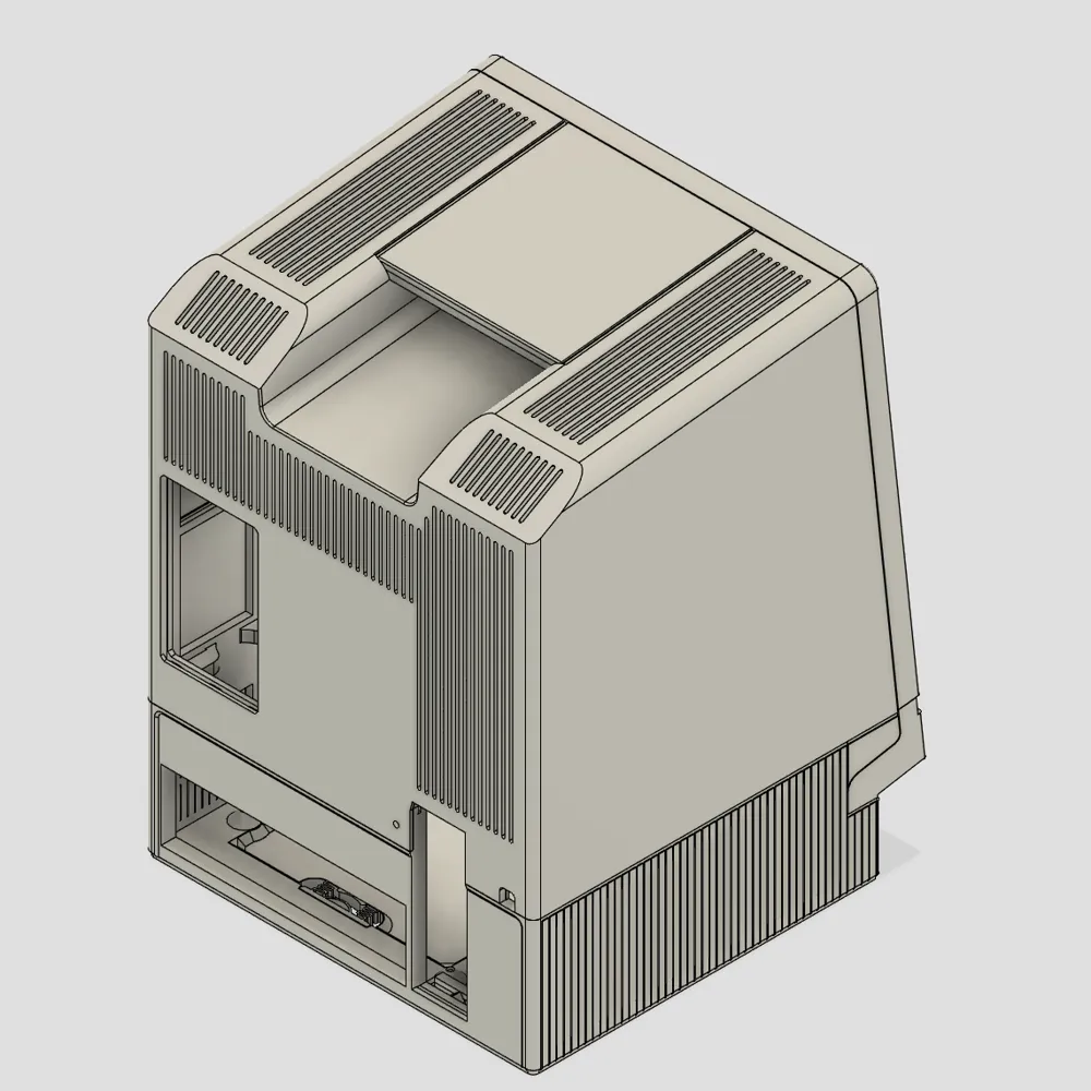
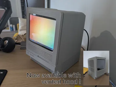
- NEW ! Vented hood available for high-end systems (better airflow) - Use the Alternate Hoods print profile
- Designed with no post-processing and minimal supports ; almost print-and-play (please read the whole manual first !)
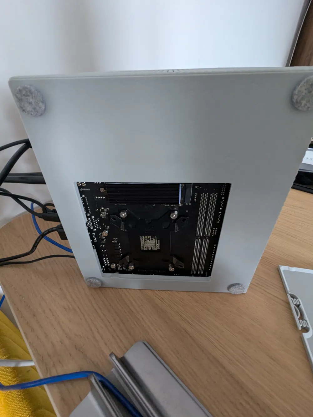
- Mini-ITX motherboard support
- SFX PSU
- CPU cooler up to 75mm
- Horizontal GPU support up to 200mm, double slot width
- Vertical GPU support up to 268mm, double slot width
- 120mm top exhaust fan
- Three 2.5 inch drive support
- Integrated screen, using Ipad 3 glass and panel
- Integrated speakers
- Front IO
- Power & reset switches, power and activity LEDs
- Front extension port, for a floppy drive / slot-in 2.5 inch drive bay
READ BEFORE PRINTING OR BUYING PARTS
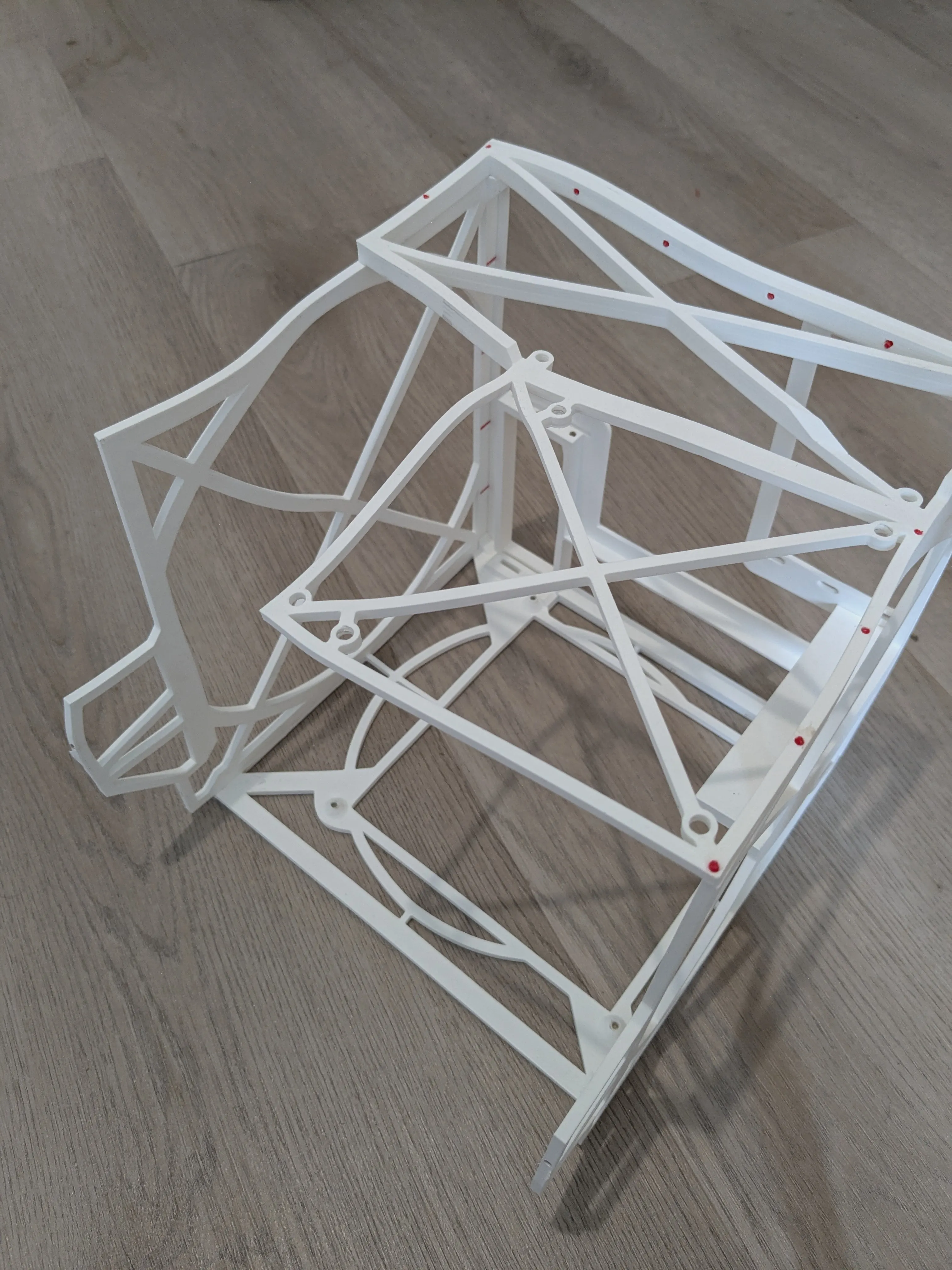
- READ. THE. WHOLE. MANUAL. FIRST.
- You will need the full horizontal build plate by following this guide → Print volume limitations, and how to use the full build volume 256x256x256mm³ | Bambu Lab Wiki
- Packintosh SE is still a complex build. I've done my utmost best to design parts that can be easily printed and assembled, but bad things can (and will) happen.
- Packintosh SE aims to fit a modern, 500W+ computer in a case designed in the 80s for a 60W computer. Airflow will not be great. Your components may suffer or break because of this, you have been warned !
- Packintosh SE can be printed out of PLA, but the result will be… less than convincing. ABS/ASA or better is strongly recommanded ; I personally chose ABS-GF for the dimensional stability, but any fiber-reinforced type of ABS/ASA should do just fine.
Parts list
- Approx. two kilos (two standard spools) of filament
- ABS/ASA, fiber reinforced highly recommended
- Bambu Lab ABS-GF in light grey matches the original “platinum” look
- Mini-ITX PC build
- SFX PSU
- CPU cooler up to 75mm
- Two slot GPU
- up to 200mm
- up to 268mm if using the vertical mount, along with :
- A PCIe riser (200mm works well)
- Extension cables for the GPU IO
- One top fan, 120mm (highly recommended for good airflow)
- Up to three 2.5 internal drive
- Adhesive, like CA glue, and/or filament-solvent slurry (Acetone works well with ABS-GF)
- For this build, I've brushed pure acetone on the faces to weld, and added some CA glue on top : it worked extremely well
- Double sided tape (optional but really helpful)
- Set of standard PC building screws - these should come with your computer :
- 4 #6-32 UNC for the motherboard
- 4 #6-32 UNC (flanged hex) for the PSU
- 1-2 #6-32 UNC for the GPU (depending on width)
- 1 #6-32 UNC for the hood (can be a thumbscrew)
- Three self-tapping screws for the fan
- An Ipad 3 or 4 panel and matching controller
- Search for SKUs LP097QX1 LP097QX1 LTL097QL01 HQ097QX1
- A good indicator is a 9.7 inch, 2048x1536 display
- I used a VSDISPLAY VS-TY2556-V869 that came with both the screen and controller
- An Ipad 3 glass/digitizer assembly
- Search for replacement screens for SKUs A1416 A1403 A1430
The following parts are not standardized ; here are the ones I've used (links are for reference only)
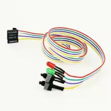
- Power, reset button, power and activity LEDs
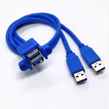
- Front IO cable
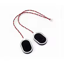
- Integrated speakers
- https://www.aliexpress.com/item/1005010413645810.html - the 4 pin variety
- The VS-TY2556-V869 has an audio connector that fits these speakers
- Display and power cables
- 90 degrees connectors can be useful for the vertical mount, but check for clearance beforehand
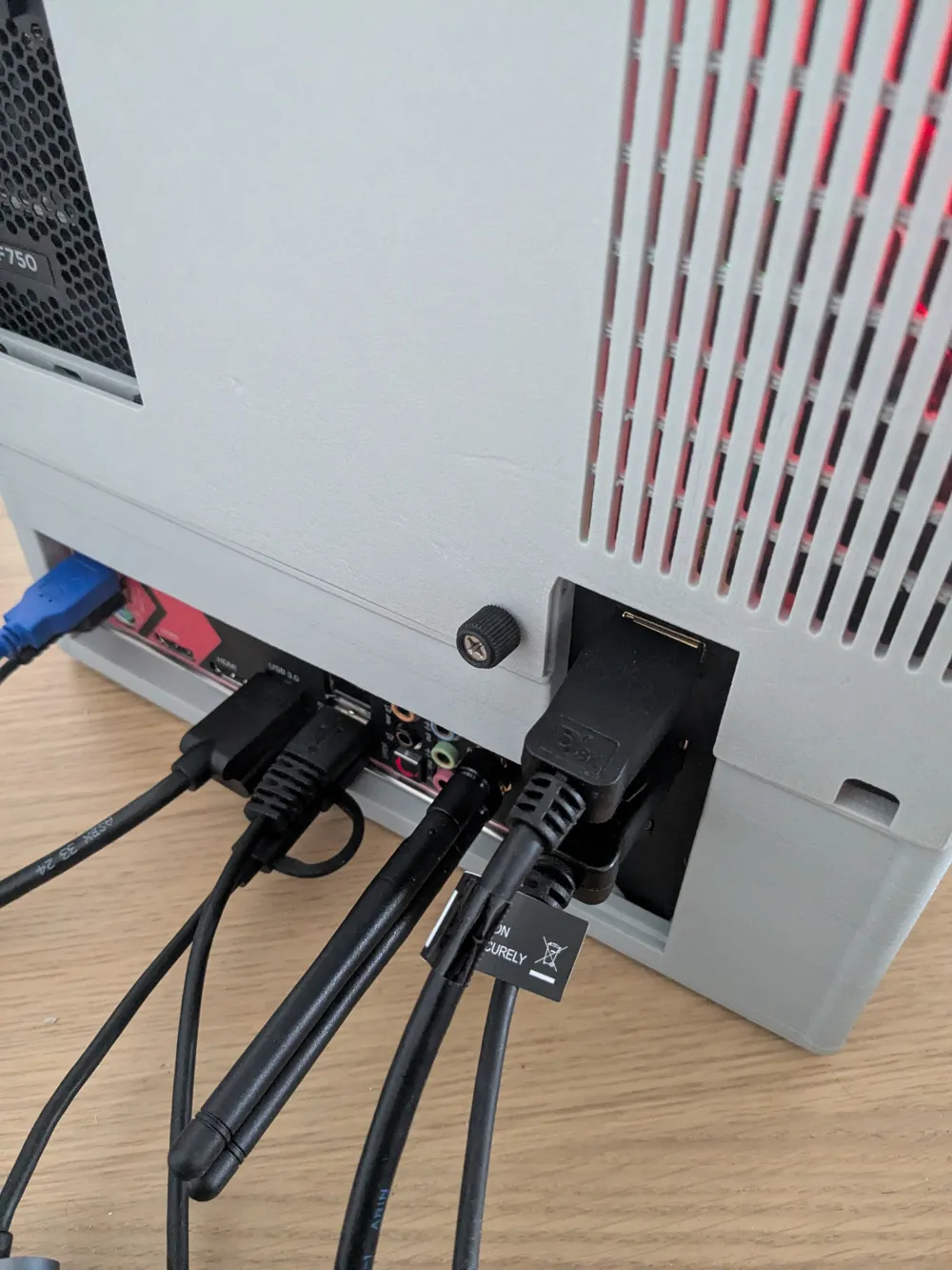
- I recommend using a SATA to Molex adapter for the screen power : splice a USB cable on the 5v cables (red and black) of the adapter to supply power directly from the PSU. Alternatively, you can also use an internal USB2.0 header, or even a USB port on the motherboard by routing a cable via the case back cutout.
Printing
The .3mf should contain all the parameters for a good print : I'm using a 0.6mm nozzle on a P1S with the full build plate modification → Print volume limitations, and how to use the full build volume 256x256x256mm³ | Bambu Lab Wiki
You only need to print the mechanical stopper and install it ; the included profile will remove the excluded bed area (no modifications are needed for the Z axis)
Base settings are :
- Wall generator : Arachne
- Enable Supports
The hood has :
- Support type : Tree (manual) and only the handle ridge painted as supported
The chassis top, chin, and small pieces have :
- Brim type : outer brim only
Chassis top (screen bezel) printing tip : When printing the bezel, the inital purge line (L shaped) will be embedded in the top, leaving a distracting printing artifact ; to easily prevent that, quickly remove it from the bed right after it's printed ! You can pause the print if you need more time.
Building
Inner chassis
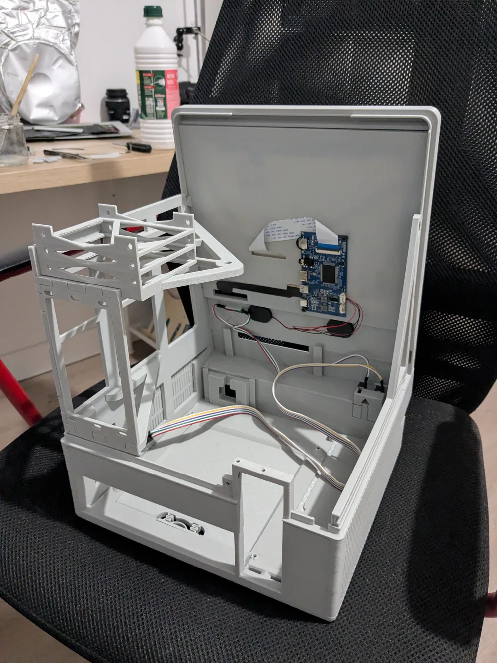
Assemble all the right parts of the inner chassis and glue together.
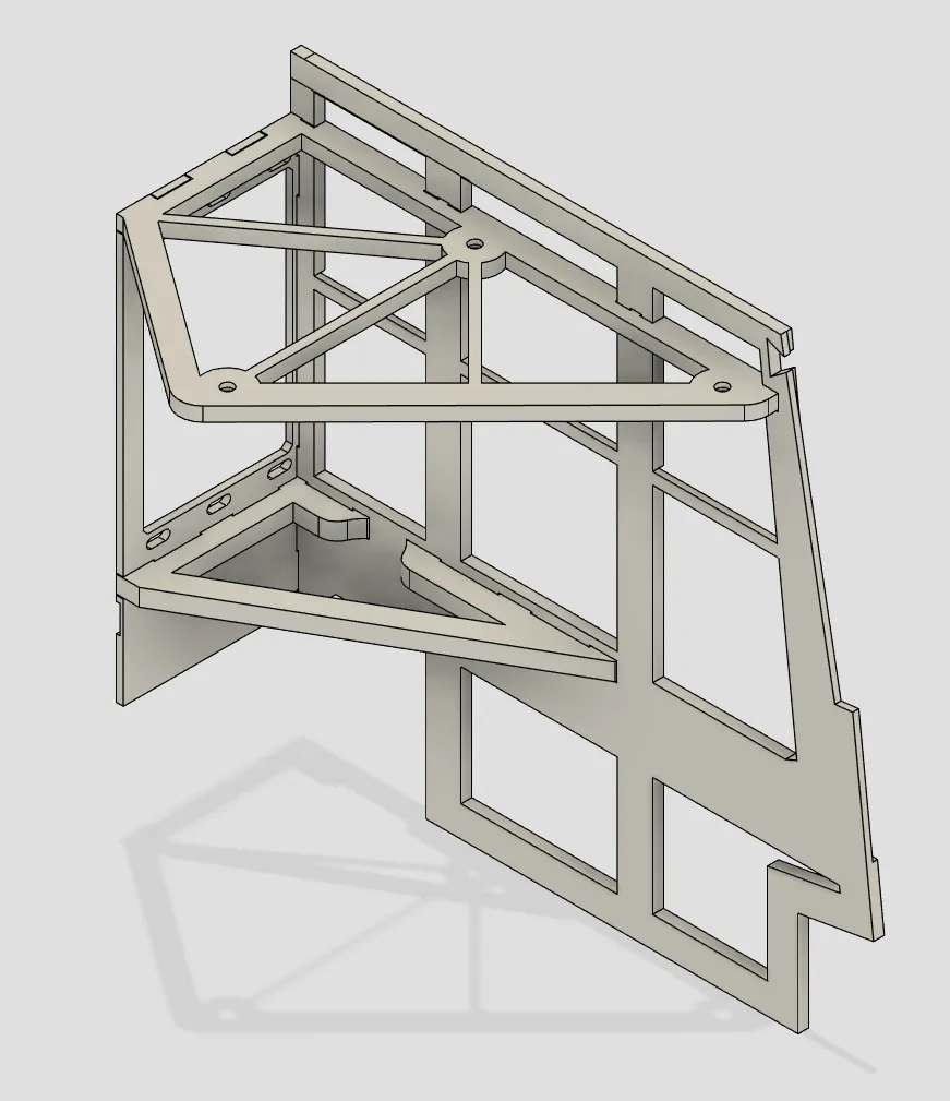
You can then glue the SSD holder on top of the assembly.
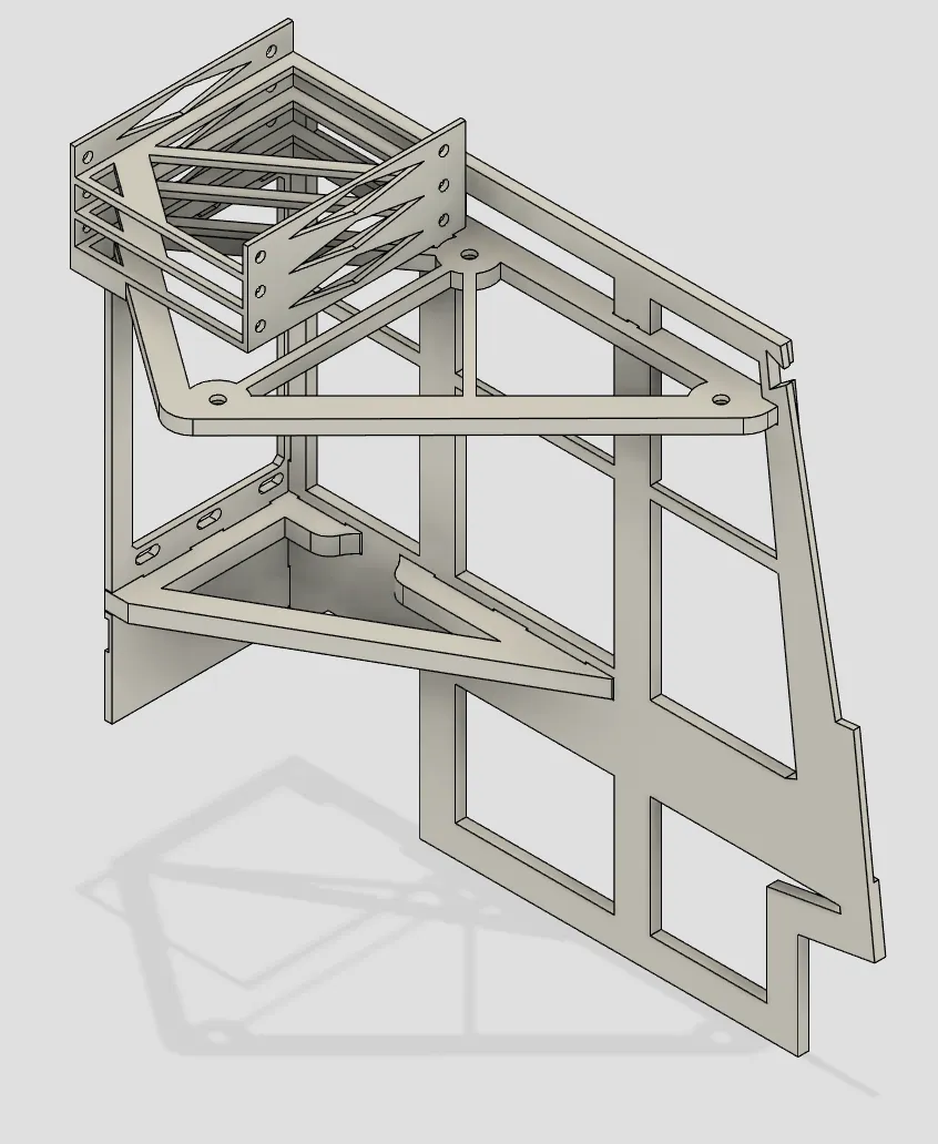
Glue the full right assembly on the base of the chassis.
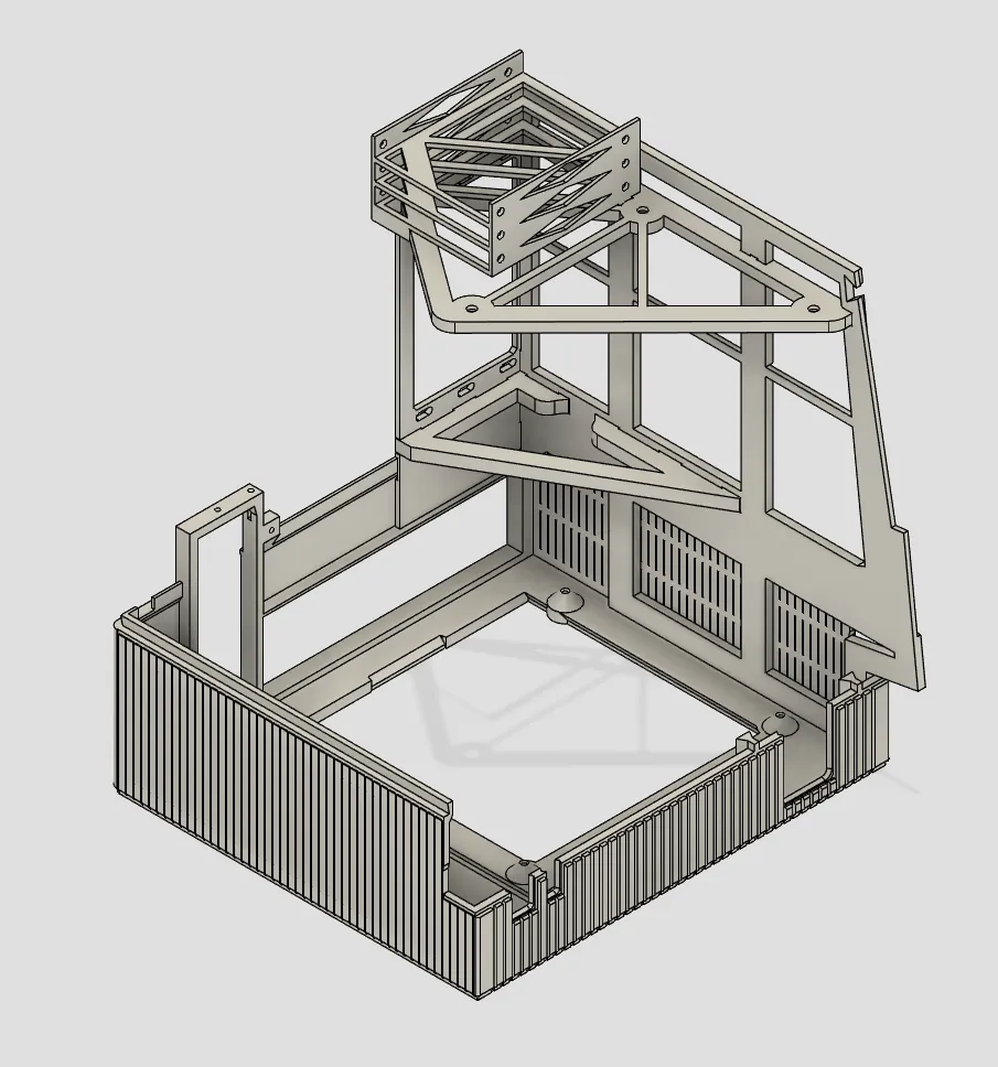
Glue the left inner bracket on the chassis.
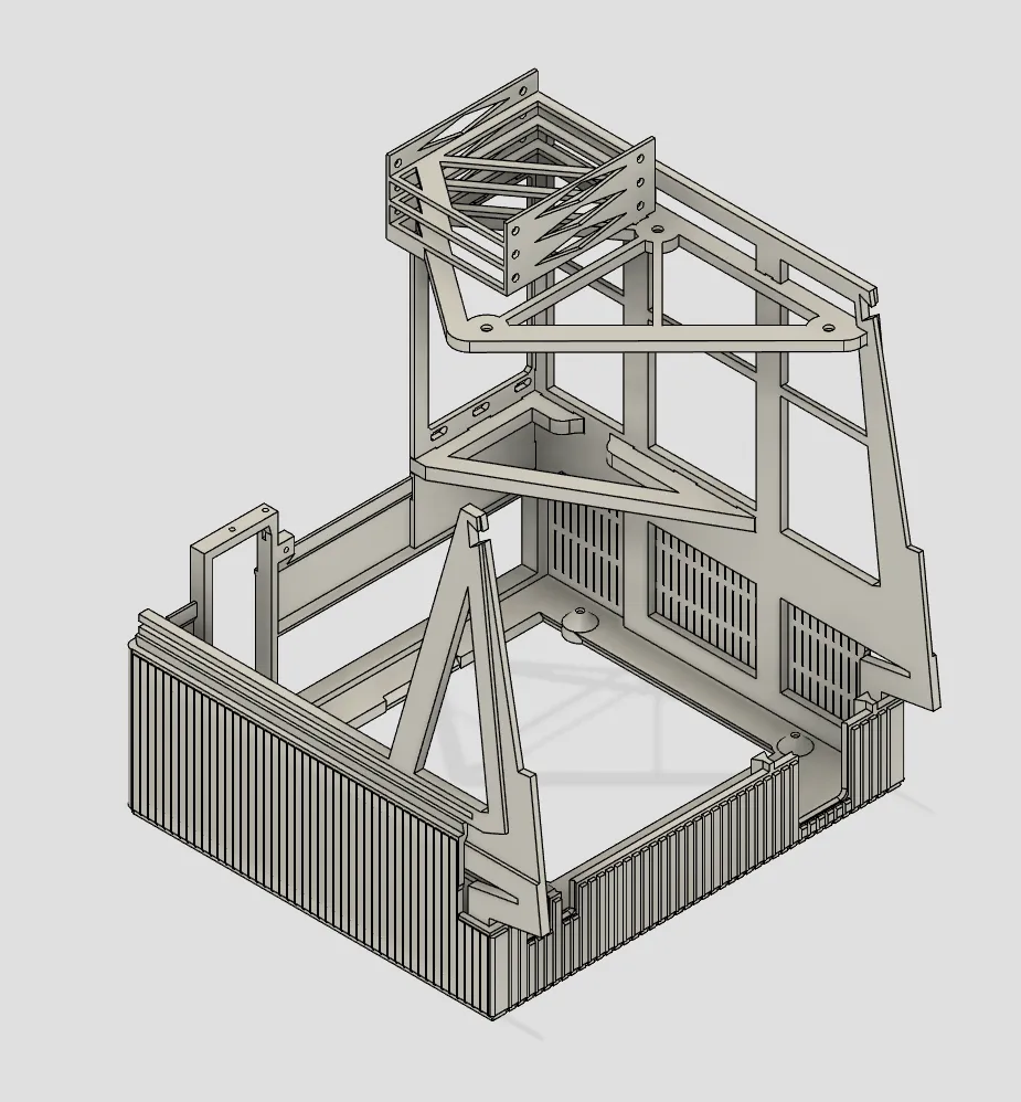
Install the front IO cover and power/reset swatches by sliding them in the recesses ; gluing is optional but recommended.
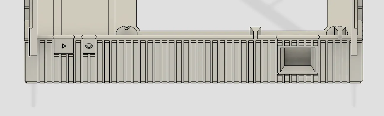
Slide the power/reset assembly on the chin (gluing optional).
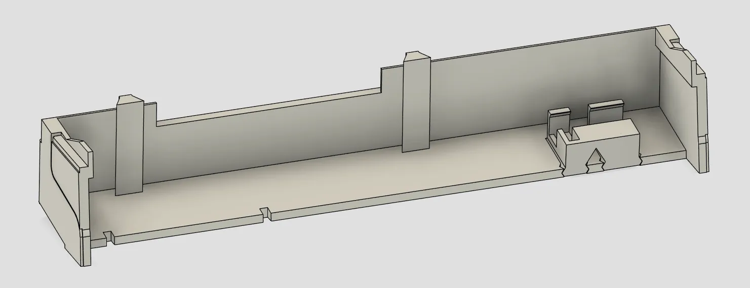
Glue the chin to the rest of the chassis. Alignment is done with the ribs on the lower chassis and side plates.
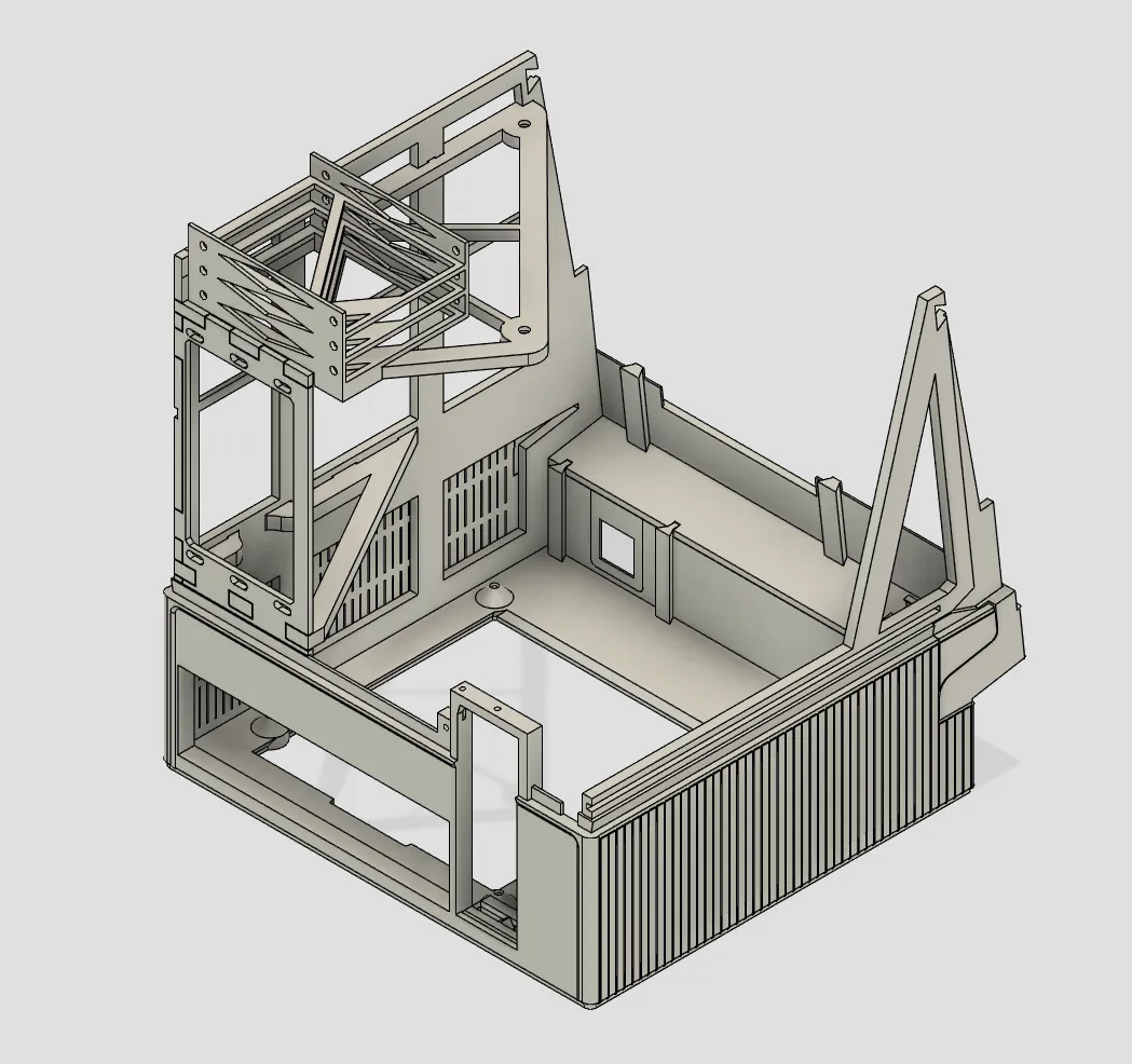
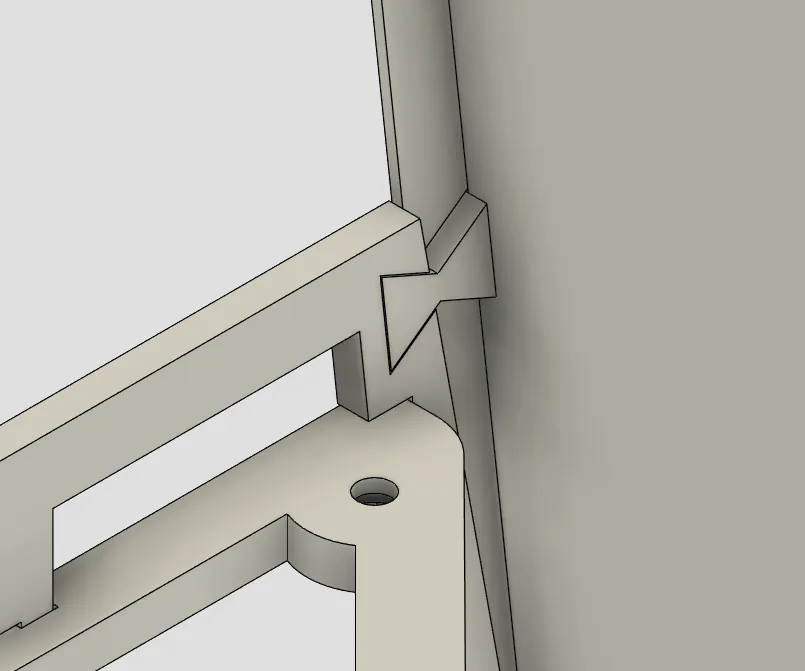
Finally, glue the screen bezel. Follow the recesses for alignment ; the butterfly cutouts near the middle of the screen are a good indicator of alignment.
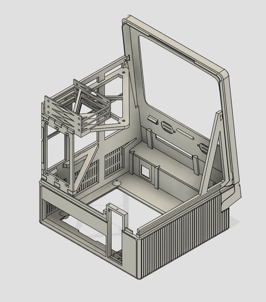
After that, check for gaps between the bottom, mid and top part of the chassis ; thin strips of filament (from brims) can be brushed on the inside with glue to light-seal the cracks.
Congratulations, the gluing is now over ;)
You can also install the trap door ; depress the spring and rotate it into place.
Screen Assembly
Use the mounting holes to secure the LCD driver. If using a different one, you will need to design an adapter plate, or glue/stick the driver on the assembly.
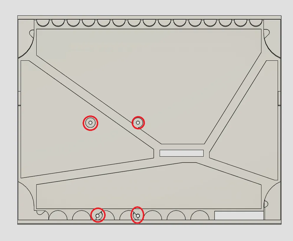
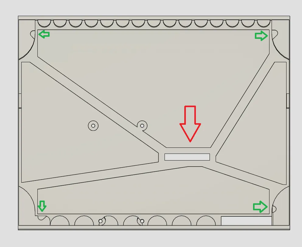
Feed the LCD panel ribbon through the middle cutout (red) and apply bits of double sided tape on all the mounting recesses (green). Secure the LCD panel on the frame.
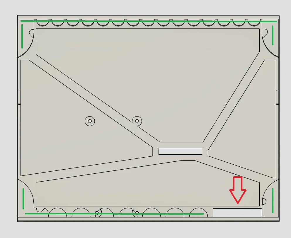
Feed the digitizer ribbon through the bottom cutout (red), and apply double sided tape on all the raised surfaces (green). Secure the glass/digitizer on the frame.
You can now connect the screen ribbon to the controller.
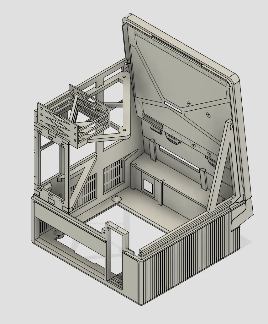
Once all assembled, slide the screen assembly on the chassis, and secure with the butterfly wedges (should be a slight friction fit, reprint the wedges if too loose / too tight).
Install the speakers, LEDs and switches. Speakers should have an adhesive on them, LEDs can slide in the recesses, and switch are snap-fit.
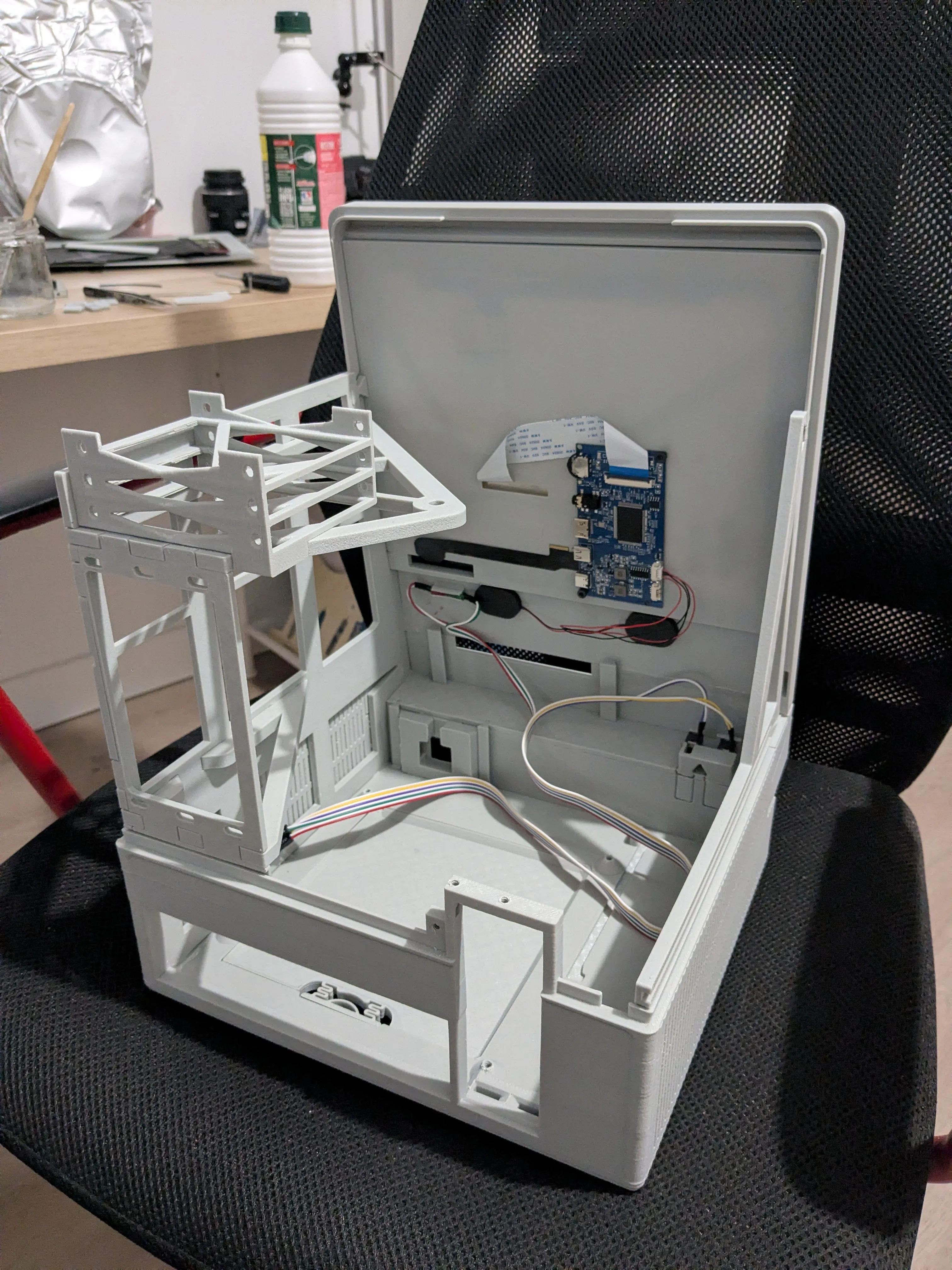
PC Build
You can now remove the screen assembly for easier installation of the components (remove the butterfly wedges and slide the assembly out)
Install the top fan.
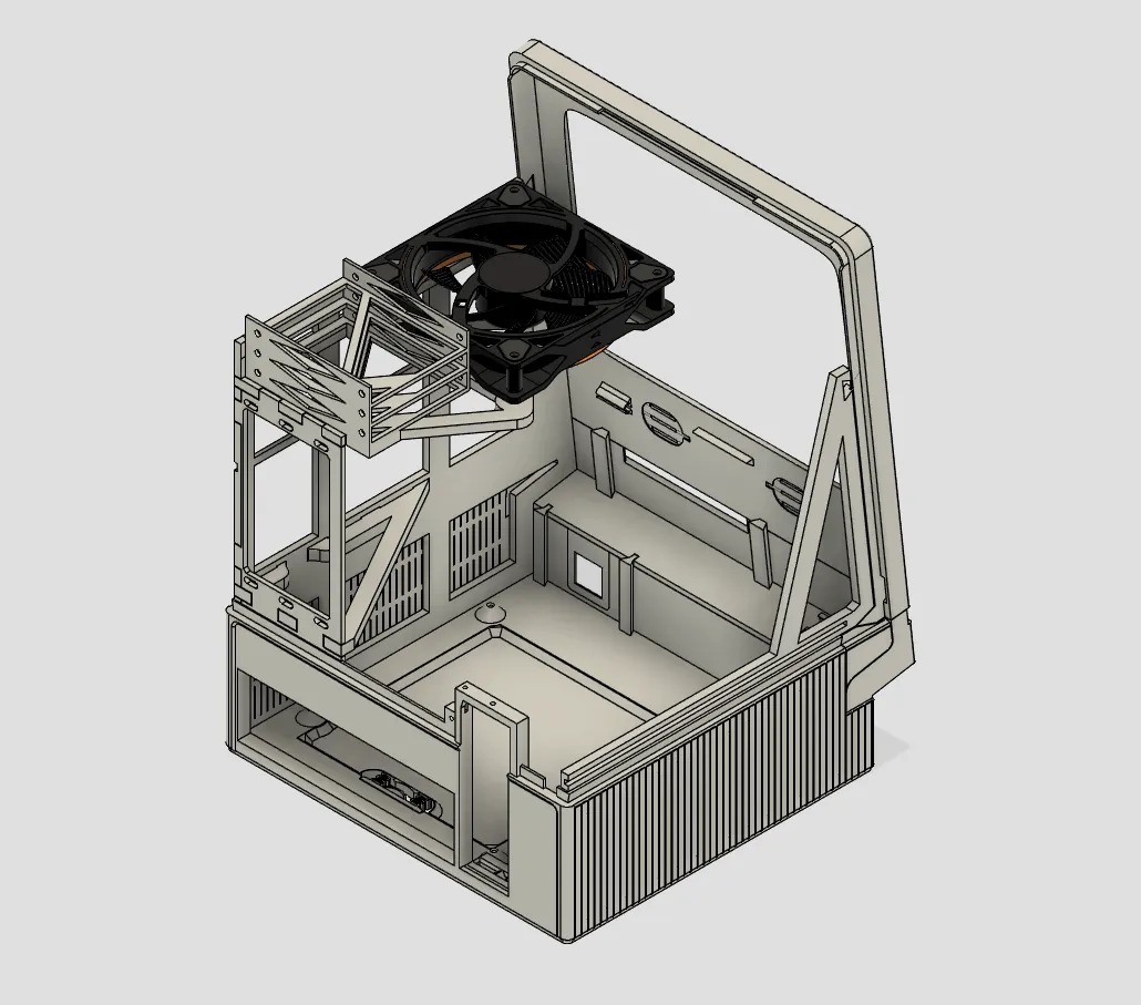
Install the IO shield and motherboard ; preconnect as much cables as you can as things will be crowded afterwards
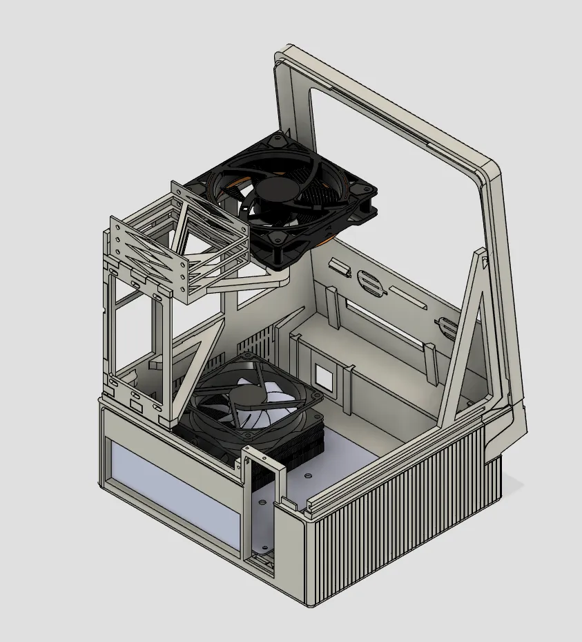
Install the SSDs on the bracket.
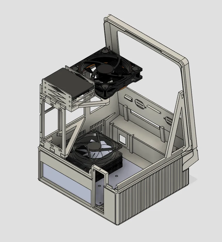
Install the PSU.
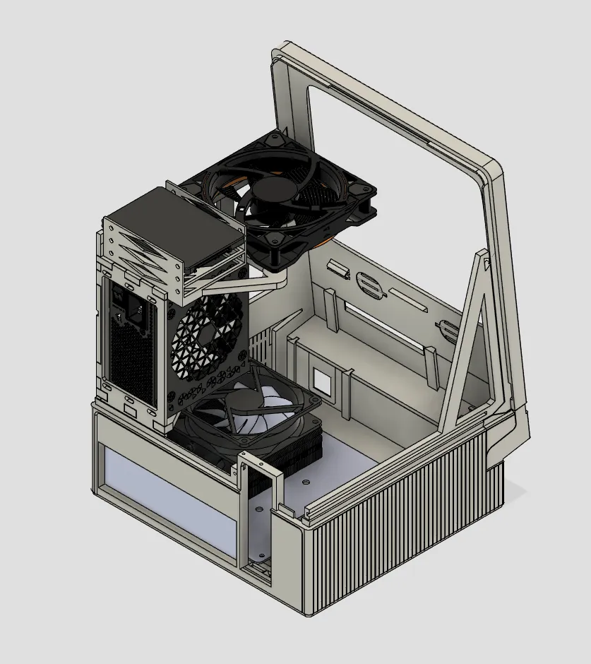
Connect the front IO to the motherboard. Install the front USB ; if you're using the same double USB3.0, you will likely need to modify it slightly by cutting a bit of the rubber sleeve ; this will allow it to bend enough and clear the 24pin ATX connector of the motherboard.
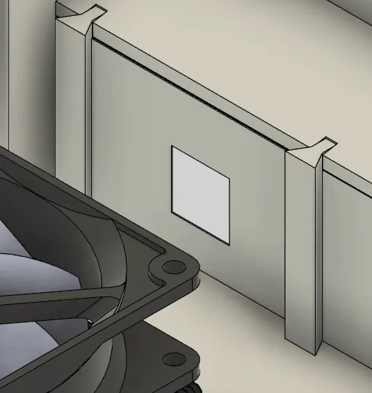
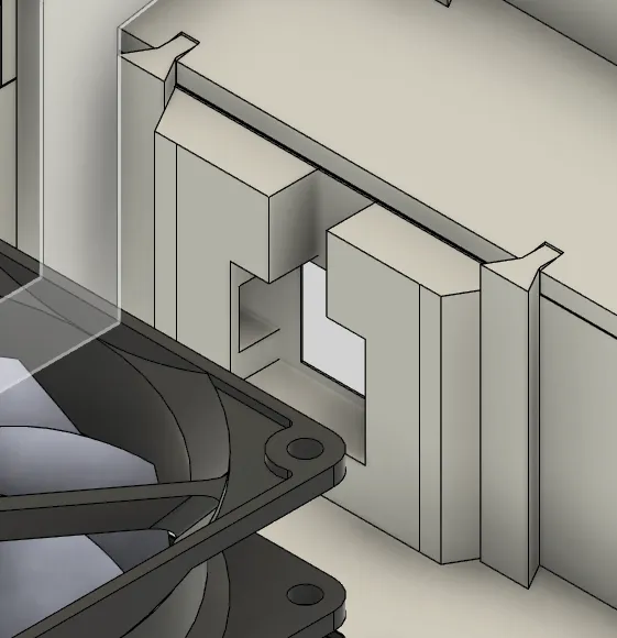
The case comes with a front extension port, but by default a blank is used to hide the hole. You can slide it into place.
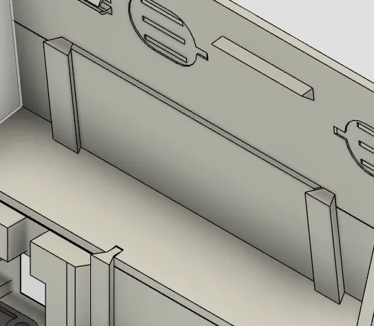
Tidy up the cables as best you can. You can now reinstall the screen assembly.
GPU installation
Horizontal
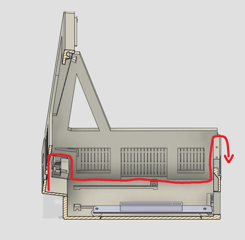
Insert the GPU into the PCIe slot and secure to the frame. You can route the display cable from the screen driver to the back like so :
Vertical
Screw the GPU on the vertical holder without installing it in the chassis. Connect and route the display cables (front is screen driver, back is other IO). Lower the assembly in the chassis and into the cutout ; a small strip of double sided tape on the feet of the vertical holder will help. Secure the holder with the lock pins.
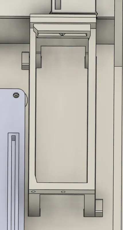
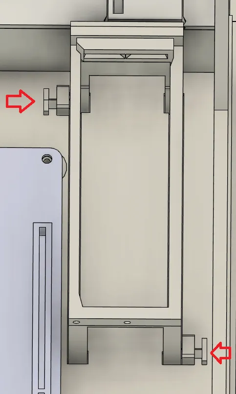
You will need to fashion an adapter plate for the GPU cables - a blank can be used as as starting template (PCI-e Blank Plate Low Profile)
Final assembly
Check that everything is working properly.
You can now slide the lock tabs onto the hood.
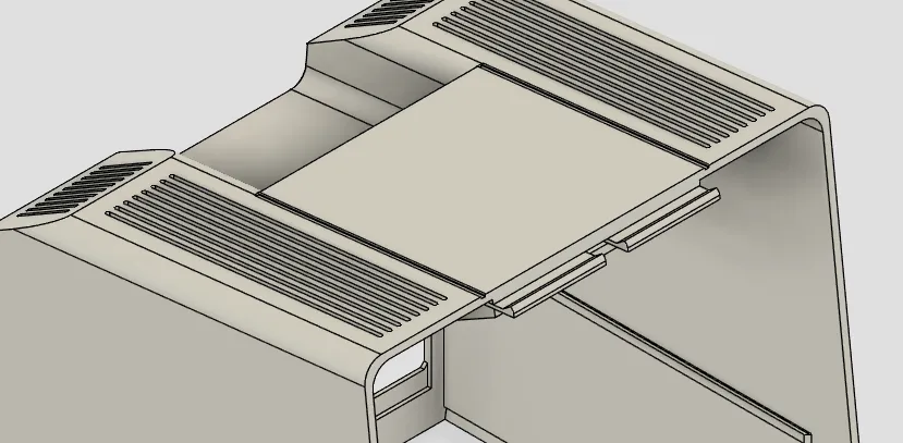
And slide the hood along the rails. Be mindful of the alignment wings at the bottom. If everything fits, it should click in place.
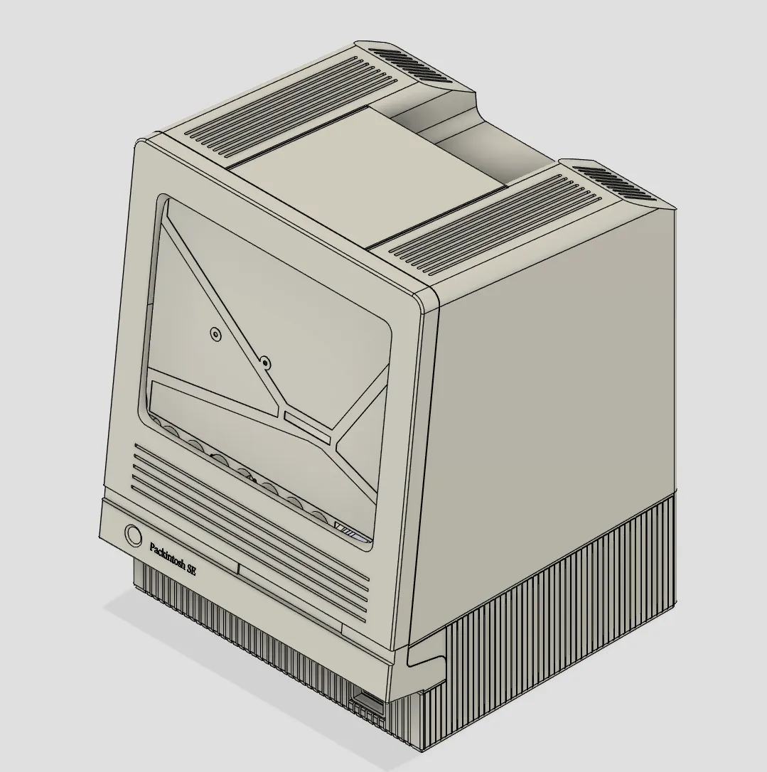
Use a (thumb) screw to secure the hood. You can install felt pads on the bottom to avoid scratching your table ;) All done ! Congrats !
License



Comment & Rating (6)