Bad Pico! - A Cheap BadUSB Alternative


Print Profile(1)

Description
Boost Me (for free)
💜 If you like my work and what I do consider boosting my model! 💜
Disclaimer:
I do not endorse or condone any misuse of the BadPico. The user is solely responsible for ensuring that it is applied in a lawful and ethical manner. I assume no liability for improper use.
Description
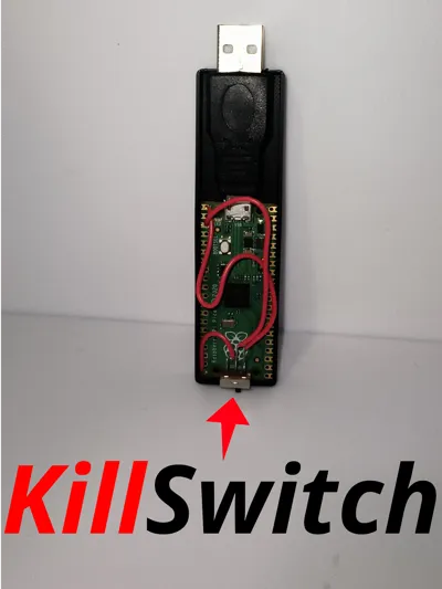
Tasks over tasks, boring and repetitive, if only there was a way to automate them… Introducing BadPico! This BadUSB Alternative is the easiest and cheapest way to automate mundane and repetitive tasks. The BadPico boasts a “KillSwitch” that switches between setup mode where you can change the running script and a running mode where the BadPico will execute the code when plugged in.
To start I recommend setting up the Rubber Ducky firmware and understanding how it works before the assembly of the components, you can see how here: GitHub Link and here Youtube Link
Specs
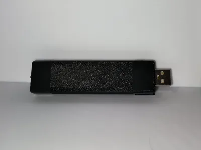
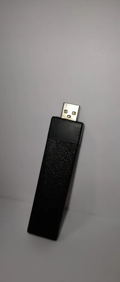
- Parts Included: Upper and Lower body of the case
- Size: 23mm (L) x 88mm (W) x 8mm (H)
- Material Recommendation: PLA/PETG
Materials for full assembly:
- Small Switch
- 3 Short Cables
- Raspberry Pi Pico
- Micro USB to USB A Adapter
- Electrical Tape
Assembly Instructions
Step 1 Solder the Switch:
In order to switch between the setup mode and running mode of the raspberry pi pico you need a switch connected as so

The middle of the switch connect to GND (Pin 3) and the two other legs of the switch to GP0 (Pin 1) and GPIO15 (Pin 20)
Step 2 Change the Case Size:
Depending on the length of your Micro USB to USB A Adapter you will need to change the dimension of the front of the case.
Measure the distance between the end of the USB connection all the way to the USB A end like in the picture and then change the case size as so


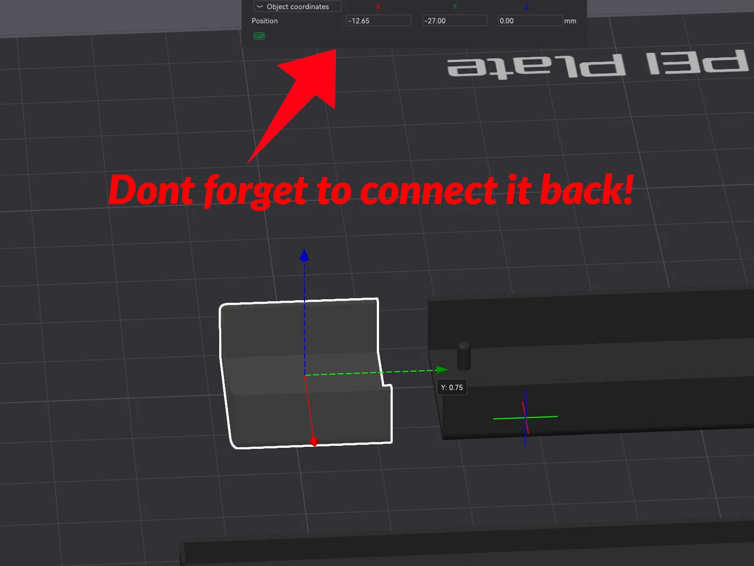
You need to do this for the bottom and upper case
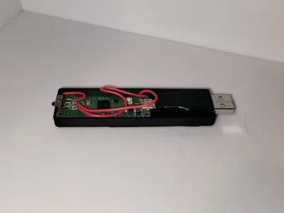
Step 3 Connect them all:
After printing the case put the pico in place with the adapter connected and the small switch in the back gap of the case, after that you can either put electrical tape to keep it shut or solder the plastic shut (do keep in mind this will seal it permanently)
License
You shall not share, sub-license, sell, rent, host, transfer, or distribute in any way the digital or 3D printed versions of this object, nor any other derivative work of this object in its digital or physical format (including - but not limited to - remixes of this object, and hosting on other digital platforms). The objects may not be used without permission in any way whatsoever in which you charge money, or collect fees.
Comment & Rating (5)